Advanced Mobile Location (AML) is being rolled out by a large number of mobile network operators to provide accurate caller location to emergency services, so how does it work, what’s going on and what do you need to know?
Recently we’ve been doing a lot of work on emergency calling in IMS, and meeting requirements for NG-112 / e911, etc.
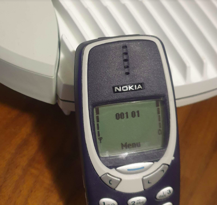
This led me to seeing my first Advanced Mobile Location (AML) SMS in the wild.
For those unfamiliar, AML is a fancy text message that contains the callers location, accuracy, etc, that is passed to emergency services when you make a call to emergency services in some countries.
It’s sent automatically by your handset (if enabled) when making a call to an emergency number, and it provides the dispatch operator with your location information, including extra metadata like the accuracy of the location information, height / floor if known, and level of confidence.
Google has their own version of AML called ELS, which they claim is supported on more than 99% of Android phones (I’m unclear on what this means for Harmony OS or other non-Google backed forks of Android), and Apple support for AML starts from iOS 11 onwards, meaning it’s supported on iPhones from the iPhone 5S onards,.
Call Flow
When a call is made to the PSAP based on the Emergency Calling Codes set on the SIM card or set in the OS, the handset starts collecting location information. The phone can pull this from a variety of sources, such as WiFi SSIDs visible, but the best is going to be GPS or one of it’s siblings (GLONASS / Galileo).
Once the handset has a good “lock” of a location (or if 20 seconds has passed since the call started) it bundles up all of this information the phone has, into an SMS and sends it to the PSAP as a regular old SMS.
The routing from the operator’s SMSc to the PSAP, and the routing from the PSAP to the dispatcher screen of the operator taking the call, is all up to implementation. For the most part the SMS destination is the emergency number (911 / 112) but again, this is dependent on the country.
Inside the SMS
To the user, the AML SMS is not seen, in fact, it’s actually forbidden by the standard to show in the “sent” items list in the SMS client.
On the wire, the SMS looks like any regular SMS, it can use GSM7 bit encoding as it doesn’t require any special characters.
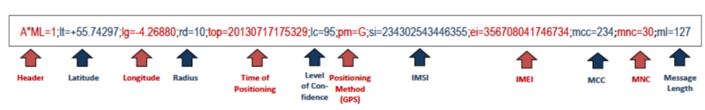
Each attribute is a key / value pair, with semicolons (;) delineating the individual attributes, and = separating the key and the value.
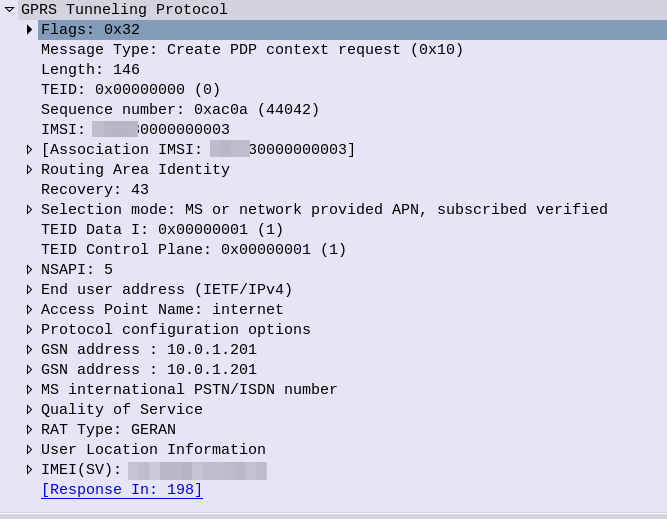
If you’ve got a few years of staring at Wireshark traces in Hex under your belt, then this will probably be pretty easy to get the gist of what’s going on, we’ve got the header (A”ML=1″) which denotes this is AML and the version is 1.
After that we have the latitude (lt=), longitude (lg=), radius (rd=), time of positioning (top=), level of confidence (lc=), positioning method (pm=) with G for GNSS, W for Wifi signal, C for Cell or N for a position was not available, and so on.
AML outside the ordinary
Roaming Scenarios
If an emergency occurs inside my house, there’s a good chance I know the address, and even if I don’t know my own address, it’s probably linked to the account holder information from my telco anyway.
AML and location reporting for emergency calls is primarily relied upon in scenarios where the caller doesn’t know where they’re calling from, and a good example of this would be a call made while roaming.
If I were in a different country, there’s a much higher likelihood that I wouldn’t know my exact address, however AML does not currently work across borders.
The standard suggests disabling SMS when roaming, which is not that surprising considering the current state of SMS transport.
Without a SIM?
Without a SIM in the phone, calls can still be made to emergency services, however SMS cannot be sent.
That’s because the emergency calling standards for unauthenticated emergency calls, only cater for
This is a limitation however this could be addressed by 3GPP in future releases if there is sufficient need.
HTTPS Delivery
The standard was revised to allow HTTPS as the delivery method for AML, for example, the below POST contains the same data encoded for use in a HTTP transaction:
Implementation of this approach is however more complex, and leads to little benefit.
The operator must zero-rate the DNS, to allow the FQDN for this to be resolved (it resolves to a different domain in each country), and allow traffic to this endpoint even if the customer has data disabled (see what happens when your handset has PS Data Off ), or has run out of data.
Due to the EU’s stance on Net Neutrality, “Zero Rating” is a controversial topic that means most operators have limited implementation of this, so most fall back to SMS.
Other methods for sharing location of emergency calls?
In some upcoming posts we’ll look at the GMLC used for E911 Phase 2, and how the network can request the location from the handset.
There’s old joke about standards that the great thing about standards there’s so many to choose from.
SMS wasn’t there from the start of GSM, but within a year of the inception of 2G we had SMS, and we’ve had SMS, almost totally unchanged, ever since.
In a recent Twitter exchange, I was asked, what’s the best way to transport SMS? As always the answer is “it depends” so let’s take a look together at where we’ve come from, where we are now, and how we should move forward.
How we got Here
Between 2G and 3G SMS didn’t change at all, but the introduction of 4G (LTE) caused a bit of a rethink regarding SMS transport.
Early builders of LTE (4G) networks launched their 4G offerings without 4G Voice support (VoLTE), with the idea that networks would “fall back” to using 2G/3G for voice calls.
This meant users got fast data, but to make or receive a call they relied on falling back to the circuit switched (2G/3G) network – Hence the name Circuit Switched Fallback.
Falling back to the 2G/3G network for a call was one thing, but some smart minds realised that if a phone had to fall back to a 2G/3G network every time a subscriber sent a text (not just calls) – And keep in mind this was ~2010 when SMS traffic was crazy high; then that would put a huge amount of strain on the 2G/3G layers as subs constantly flip-flopped between them.
The SGs-AP interface has two purposes; One, It can tell a phone on 4G to fallback to 2G/3G when it’s got an incoming call, and two; it can send and receive SMS.
SMS traffic over this interface is sometimes described as SMS-over-NAS, as it’s transported over a signaling channel to the UE.
This also worked when roaming, as the MSC from the 2G/3G network was still used, so SMS delivery worked the same when roaming as if you were in the home 2G/3G network.
Enter VoLTE & IMS
Of course when VoLTE entered the scene, it also came with it’s own option for delivering SMS to users, using IP, rather than the NAS signaling. This removed the reliance on a link to a 2G/3G core (MSC) to make calls and send texts.
This was great because it allowed operators to build networks without any 2G/3G network elements and build a fully standalone LTE only network, like Jio, Rakuten, etc.
In roaming scenarios, S8 Home Routing for VoLTE enabled SMS to be handled when roaming the same way as voice calls, which made SMS roaming a doddle.
4G SMS: SMS over IP vs SMS over NAS
So if you’re operating a 4G network, should you deliver your SMS traffic using SMS-over-IP or SMS-over-NAS?
Generally, if you’ve been evolving your network over the years, you’ve got an MSC and a 2G/3G network, you still may do CSFB so you’ve probably ended up using SMS over NAS using the SGs-AP interface. This method still relies on “the old ways” to work, which is fine until a discussion starts around sunsetting the 2G/3G networks, when you’d need to move calling to VoLTE, and SMS over NAS is a bit of a mess when it comes to roaming.
Greenfield operators generally opt for SMS over IP from the start, but this has its own limitations; SMS over IP is has awful efficiency which makes it unsuitable for use with NB-IoT applications which are bandwidth constrained, support for SMS over IP is generally limited to more expensive chipsets, so the bargain basement chips used for IoT often don’t support SMS over IP either, and integration of VoLTE comes with its own set of challenges regarding VoLTE enablement.
5G enters the scene (Nsmsf_SMService)
5G rolled onto the scene with the opportunity to remove the SMS over NAS option, and rely purely on SMS over IP (IMS); forcing the industry to standardise on an option alas this did not happen.
This added another option for SMS delivery dependent on the access network used, and the Nsmsf_SMService interface does not support roaming.
Of course if you are using Voice over NR (VoNR) then like VoLTE, SMS is carried in a SIP message to the IMS, so this negates the need for the Nsmsf_SMService.
2G/3G Shutdown – Diameter to replace SGs-AP (SGd)
With the 2G/3G shutdown in the US operators who had up until this point been relying on SMS-over-NAS using the SGs-AP interface back to their MSCs were forced to make a decision on how to route SMS traffic, after the MSCs were shut down.
This landed with SMS-over-Diameter, where the 4G core (MME) communicates over Diameter with the SMSc.
This has adoption by all the US operators, but we’re not seeing it so widely deployed in the rest of the world.
State of Play
Option
Conditions
Notes
MAP
2G/3G Only
Relies on SS7 signaling and is very old Supports roaming
SGs-AP (SMS-over-NAS)
4G only relies on 2G/3G
Needs an MSC to be present in the network (generally because you have a 2G/3G network and have not deployed VoLTE) Supports limited roaming
SMS over IP (IMS)
4G / 5G
Not supported on 2G/3G networks Relies on a IMS enabled handset and network Supports roaming in all S8 Home Routed scenarios Device support limited, especially for IoT devices
Diameter SGd
4G only / 5G NSA
Only works on 4G or 5G NSA Better device support than 4G/5G Supports roaming in some scenarios
Nsmsf_SMService
5G standalone only
Only works on 5GC Doesn’t support roaming
The convoluted world of SMS delivery options
A Way Forward:
While the SMS payload hasn’t changed in the past 31 years, how it is transported has opened up a lot of potential options for operators to use, with no clear winner, while SMS revenues and traffic volumes have continued to fall.
For better or worse, the industry needs to accept that SMS over NAS is an option to use when there is no IMS, and that in order to decommission 2G/3G networks, IMS needs to be embraced, and so SMS over IP (IMS) supported in all future networks, seems like the simple logical answer to move forward.
And with that clear path forward, we add in another wildcard…
But, when you’ve only got a finite resource of bandwidth, and massive latencies to contend with, the all-IP architecture of IMS (VoLTE / VoNR) and it’s woeful inefficiency starts to really sting.
Of course there are potential workarounds here, Robust Header Correction (ROHC) can shrink this down, but it’s still going to rely on the 3 way handshake of TCP, TCP keepalive timers and IMS registrations, which in turn can starve the radio resources of the satellite link.
Even with SMS over 30 years old, we can still expect it to be a part of networks for years to come, even as WhatsApp / iMessage, etc, offer enhanced services. As to how it’s transported and the myriad of options here, I’m expecting that we’ll keep seeing a multi-transport mix long into the future.
For simple, cut-and-dried 4G/5G only network, IMS and SMS over IP makes the most sense, but for anything outside of that, you’ve got a toolbox of options for use to make a solution that best meets your needs.
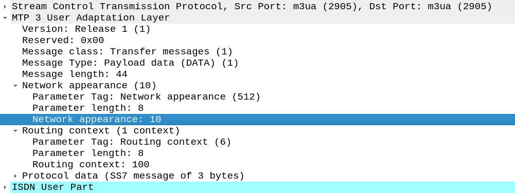
Short one, The other day I needed to add a Network Appearance on an SS7/SS7 M3UA linkset.
Network Appearances on M3UA links are kinda like a port number, in that they allow you to distinguish traffic to the same point code, but handled by different logical entities.
When I added the NA parameter on the Linkset nothing happened.
If you’re facing the same you’ll need to set:
cs7 multi-instance
In the global config (this is the part I missed).
Then select the M3UA linkset you want to change and add the network-appearance parameter:
network-appearance 10
And bingo, you’ll start seeing it in your M3UA traffic:
If you’ve ever worked in roaming, you’ll probably have had the misfortune of dealing with Transferred Account Procedures aka TAP files.
It’s used for billing a 2G GSM call right up to 5G data usage, if you use a service while roaming, somewhere in the world there’s a TAP file with your usage in it.
A brief history of TAP
TAP was originally specified by the GSMA in 1991 as a standard CDR interchange format between operators, for use in roaming scenarios.
Notice I said GSMA – Not 3GPP – This means there’s no 3GPP TS docs for this, it’s defined by the industry lobby group’s members, rather than the standards body.
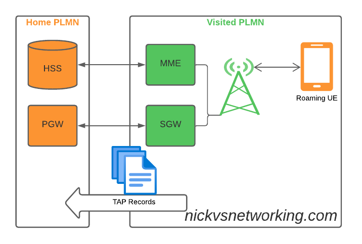
So what does this actually mean? Well, if you’re MNO A and a customer from MNO B roams into your network, all the calls, SMS and data consumed by the roaming subscriber from MNO B will need to be billed to MNO B, by you, MNO A.
If a network operator wants to get paid for traffic used on their network by roaming subscribers, they’d better send out a TAP file to the roamer’s home network.
TAP is the file format generated my MNO A and sent to MNO B, containing all the usage charges that subscribers from MNO B have racked up while roaming into your network.
These are broken down into “Transactions” (CDRs), for events like making a call, connecting a PDN session and consuming data, or sending a text.
In the beginning of time, GSM provided only voice calling service. This meant that the only services a subscriber could consume while roaming was just making/receiving voice calls which were billed at the end of each month. – This meant billing was equally simple, every so often the visisted network would send the TAP files for the voice calls made by subscribers visited other networks, to the home networks, which would markup those charges, and add them onto the monthly invoice for each subscriber who was roaming.
But of course today, calling accounts for a tiny amount of usage on the network, but this happened gradually while passing through the introduction of SMS, CAMEL services, prepaid services, mobile data, etc. For all these services that could be offered, the TAP format had to evolve to handle each of these scenarios.
As we move towards a flat IP architecture, where voice calls and SMS sent while roaming are just data, TAP files for 4G and 5G networks only need to show data transactions, so the call objects, CAMEL parameters and SMS objects are all falling by the wayside.
What’s inside a TAP File
TAP uses the most beloved of formats – ASN1 to encode the data. This means it is strictly formatted and rigidly specified.
Each file contains a Sequence Number which is a monotonically increasing number, which allows the receiver to know if any files have been missed between the file that’s being currently parsed, an the previous file.
They also have a recipient and sender TADIG code, which is a code allocated by GSMA that uniquely identifies the sender and the recipient of the file.
The TAP records exist in one of two common format, Notification Records and transferBatch records.
These files are exchanged between operators, in practice this means “Dumped on an FTP server as agreed between the two”.
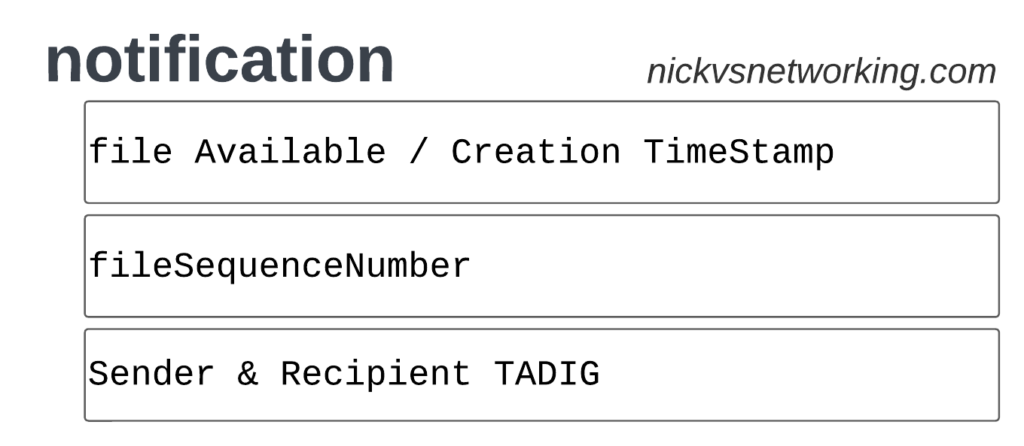
TAP Notification Records
Notifications are the simplest of TAP records and are used when there aren’t any CDRs for roaming events during the time period the TAP file covers.
These are essentially blank TAP files generated by the visited network to let the home network know it’s still there, but there are no roaming subs consuming services in that period.
Notification files are really simple, let’s take a look as one shown as JSON:
When we have services to bill and records to charge, that’s when instead we generate a transferBatch record.
It looks something like this:
There’s a lot going on in here, so let’s break it down section by section.
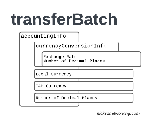
accountingInfo
The accountingInfo section specifies the currency, exchange rate parameters.
Keep in mind a TAP record generated by an operator in the US, would use USD, while the receiver of the file may be a European MNO dealing in EUR.
This gets even more complicated if you’re dealing with more obscure currencies where an intermediary currency is used, that’s where we bring in SDRs (“Special Drawing Right”) that map to the dollar value to be charged, kinda – the roaming agreement defines how many SDRs are in a dollar, in the example below we’re not using any, but you do see it.
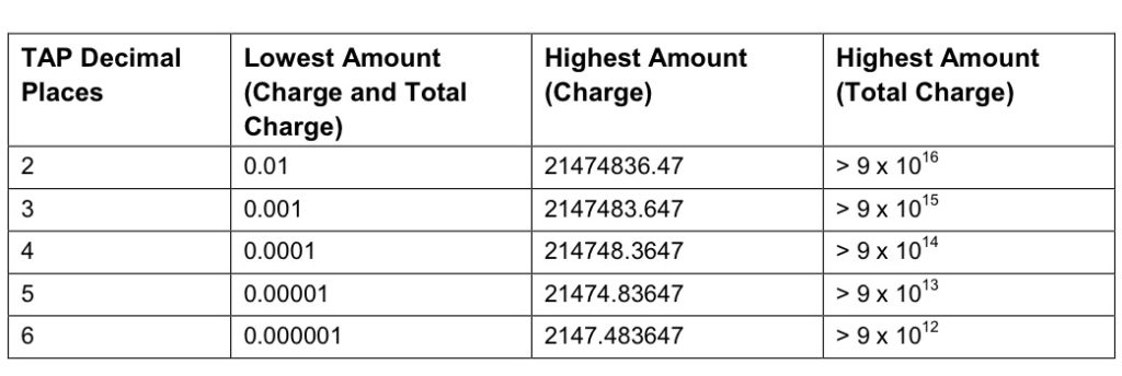
When it comes to numbers and decimal places, TAP doesn’t exactly make it easy.
Significant Digits are defined by counting the first number before the decimal point and all the numbers to the right of the decimal point, so for example the number 1.234 would be 4 significant digits (1 digit before the decimal point and 3 digits after it).
Decimal Places are not actually supported for the Value fields in the TAP file. This is tricky because especially today when roaming tariffs are quite low, these values can be quite small, and we need to represent them as an integer number. TAP defines decimal places as the number of digits after the decimal place.
When it comes to the maximum number of decimal places, this actually impacts the maximum number we can store in the field – as ASN1 strictly enforce what we put in it.
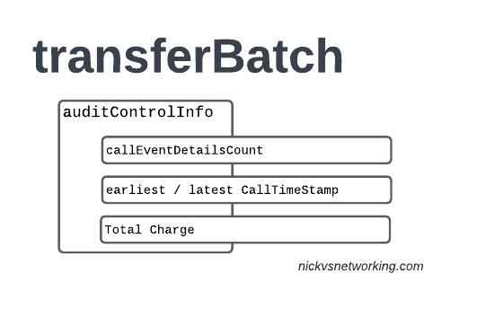
The auditControlInfo section contains the number of CDRs (callEventDetailsCount) contained in the TAP file, the timestamp of the first and last CDR in the file, the total charge and any tax charged.
All of the currency information was provided in the accountingInfo so this is just giving us our totals.
A CDR has 30 days from the time it was generated / service consumed by the roamer, to be baked into a TAP file. After this we can no longer charge for it, so it’s important that the earliestCallTimeStamp is not more than 30 days before the fileCreationTimeStamp seen in batchControlInfo.
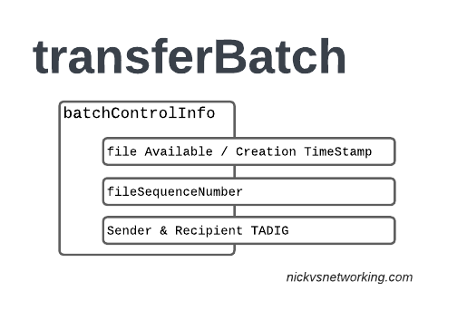
batchControlInfo
The batchControlInfo section specifies the time the TAP file became available for transfer, the time the file was created (usually the same), the sequence number and the sender / recipient TADIG codes.
As mentioned earlier, we track sequence number so the receiver can know if a TAP file has been missed; for example if you’ve got TAP file 1 and TAP file 3 comes in, you can determine you’ve missed TAP file 2.
Now we’re getting to the meat & potatoes of our TAP record, the CDRs themselves.
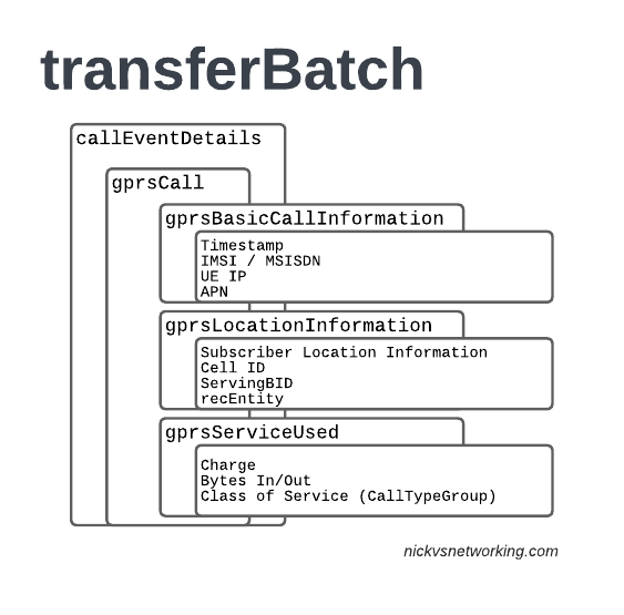
In LTE networks these are just records of data consumption, so let’s take a look inside the gprsCall records under callEventDetails:
In the gprsBasicCallInformation we’ve got as the name suggests the basic info about the data usage event. The time when the session started, the charging ID, the IMSI and the MSISDN of the subscriber to charge, along with their IP and the APN used.
Next up we have the gprsLocationInformation – rates and tariffs may be set based on the location of the subscriber, so we need to identify the area the sub was using the services to select correct tariff / rate for traffic in this destination.
The recEntity is the index number of the SGW / PGW used for the transaction (more on that later).
Next we have the gprsServiceUsed which, again as the name suggests, details the services used and the charge.
chargeDetailList contains the charged data (Made up of dataVolumeIncoming + dataVolumeOutgoing) and the cost.
The chargeableUnits indicates the actual data consumed, however most roaming agreements will standardise on some level of rounding, for example rounding up to the nearest Kilobyte (1024 bytes), so while a sub may consume 1025 bytes of data, they’d be billed for 2045 bytes of data. The data consumed is indicated in the chargeableUnits which indicates how much data was actually consumed, before any rounding policies where applied, while the amount that is actually charged (When taking into account rounding policies) isindicated inside Charged Units.
In the example below data usage is rounded up to the nearest 1024 bytes, 134390 bytes rounds up to the nearest 1024 gives you 135168 bytes.
As this is data we’re talking bytes, but not all bytes are created equal!
VoLTE traffic, using a QCI1 bearer is more valuable than QCI 9 cat videos, and TAP records take this into account in the Call Type Groups, each of which has a different price – Call Type Level 1 indicates the type of traffic, for S8 Home Routed LTE Traffic this is 10 (HGGSN/HP-GW), while Call Type Level 2 indicates the type of traffic as mapped to QCI values:
So Call Type Level 2 set to 20 indicates that this is “20 Unspecified/default LTE QCIs”, and Call Type Level 3 can be set to any value based on a defined inter-operator tariff.
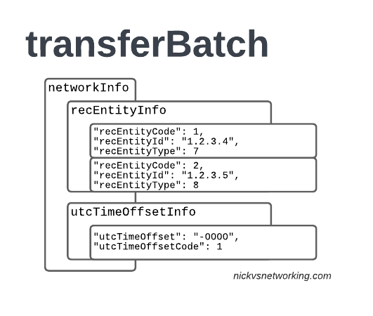
recEntityType 7 means a PGW and contains the IP of the PGW in the Home PLMN, while recEntityType 8 means SGW and is the SGW in the Visited PLMN.
So this means if we reference recEntityCode 2 in a gprsCall, that we’re referring to an SGW at 1.2.3.5.
Lastly also got the utcTimeOffsetInfo to indicate the timezones used and assign a unique code to it.
Using the Records
We as humans? These records aren’t meant for us.
They’re designed to be generated by the Visited PLMN and sent to to the home PLMN, which ingests it and pays the amount specified in the time agreed.
Generally this is an FTP server that the TAP records get dumped into, and an automated bank transfer job based on the totals for the TAP records.
Testing of the TAP records is called “TADIG Testing” and it’s something we’ll go into another day, but in essence it’s validating that the output and contents of the files meet what both operators think is the contract pricing and specifications.
So that’s it! That’s what’s in a TAP record, what it does and how we use it!
GSMA are introducing BCE – Billing & Charging Evolution, a new standard, designed to last for the next 30+ years like TAP has. It’s still in its early days, but that’s the direction the GSMA has indicated it would like to go.
If you’ve ever received an SMS from your operator, and the sender was the Operator name for example, you may be left wondering how it’s done.
In IMS you’d think this could be quite simple – You’d set the From header to be the name rather than the MSISDN, but for most SMSoIP deployments, the From header is ignored and instead the c header inside the SMS body is used.
So how do we get it to show text?
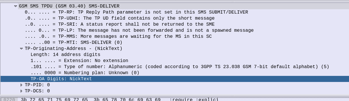
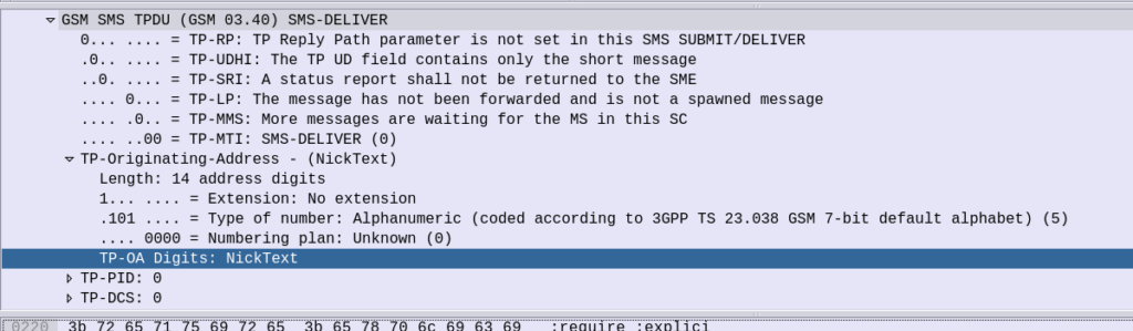
Well the TP-Originating address has the “Type of Number” (ToN) field which is typically set to International/National, but value 5 allows for the Digits to instead be alphanumeric characters.
GSM 7 bit encoding on the text in the TP-Originating Address digits and presto, you can send SMS to subscribers where the message shows as From an alphanumeric source.
On Android SMSs received from alphanumeric sources cannot be responded to (“no more “DO NOT REPLY TO THIS MESSAGE” at the end of each text), but on iOS devices you can respond, but if I send an SMS from “Nick” the reply from the subscriber using the iPhone will be sent to MSISDN 6425 (Nick on the telephone keypad).
Unstructured Supplementary Service Data or “USSD” is the stack used in Cellular Networks to offer interactive text based menus and systems to Subscribers.
If you remember topping up your mobile phone credit via a text menu on your flip phone, there’s a good chance that was USSD*.
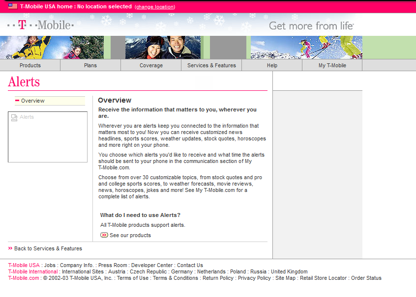
For a period, USSD Services provided Sporting Scores, Stock Prices and horoscopes on phones and networks that were not enabled for packet data.
Unlike plain SMS-PP, USSD services are transaction stateful, which means that there is a session / dialog between the subscriber and the USSD gateway that keeps track of the session and what has happened in the session thus far.
T-Mobile website from 2003 covering the features of their USSD based product at the time
Today USSD is primarily used in the network at times when a subscriber may not have balance to access packet data (Internet) services, so primarily is used for recharging with vouchers.
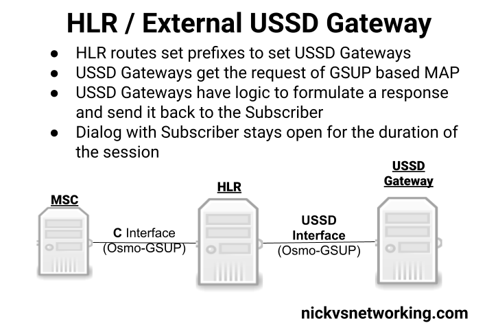
Osmocom’s HLR (osmo-hlr) has an External USSD interface to allow you to define the USSD logic in another entity, for example you could interface the USSD service with a chat bot, or interface with a billing system to manage credit.
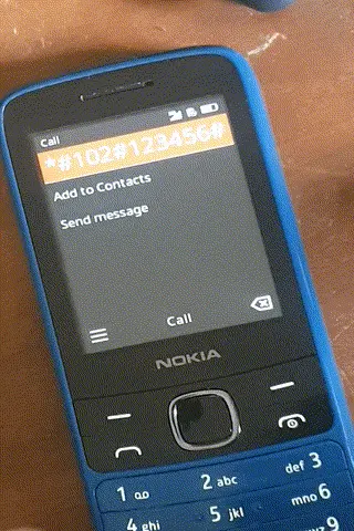
Using the example code provided I made a little demo of how the service could be used:
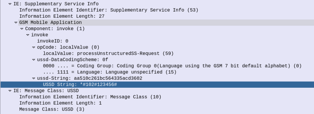
Communication between the USSD Gateway and the HLR is MAP but carried GSUP (Rather than the full MTP3/SCCP/TCAP layers that traditionally MAP stits on top of), and inside the HLR you define the prefixes and which USSD Gateway to route them to (This would allow you to have multiple USSD gateways and route the requests to them based on the code the subscriber sends).
(I had hoped to make a Python example and actually interface it with some external systems, but another day!)
The signaling is fairly straight forward, when the subscriber kicks off the USSD request, the HLR calls a MAP Invoke operation for “processUnstructuredSS-Request”
Unfortunately is seems the stock Android does not support interactive USSD. This is exposed in the Android SDK so applications can access USSD interfaces (including interactive USSD) but the stock dialer on the few phones I played with did not, which threw a bit of a spanner in the works. There are a few apps that can help with this however I didn’t go into any of them.
(or maybe they used SIM Toolkit which had a similar interface)
This is part of a series of posts looking into SS7 and Sigtran networks. We cover some basic theory and then get into the weeds with GNS3 based labs where we will build real SS7/Sigtran based networks and use them to carry traffic.
Having a direct Linkset from every Point Code to every other Point Code in an SS7 network isn’t practical, we need to rely on routing, so in this post we’ll cover routing between Point Codes on our STPs.
Let’s start in the IP world, imagine a router with a routing table that looks something like this:
Simple IP Routing Table
192.168.0.0/24 out 192.168.0.1 (Directly Attached)
172.16.8.0/22 via 192.168.0.3 - Static Route - (Priority 100)
172.16.0.0/16 via 192.168.0.2 - Static Route - (Priority 50)
10.98.22.1/32 via 192.168.0.3 - Static Route - (Priority 50)
We have an implicit route for the network we’re directly attached to (192.168.0.0/24), and then a series of static routes we configure. We’ve also got two routes to the 172.16.8.0/22 subnet, one is more specific with a higher priority (172.16.8.0/22 – Priority 100), while the other is less specific with a lower priority (172.16.0.0/16 – Priority 50). The higher priority route will take precedence.
This should look pretty familiar to you, but now we’re going to take a look at routing in SS7, and for that we’re going to be talking Variable Length Subnet Masking in detail you haven’t needed to think about since doing your CCNA years ago…
Why Masking is Important
A route to a single Point Code is called a “/14”, this is akin to a single IPv4 address being called a “/32”.
We could setup all our routing tables with static routes to each point code (/14), but with about 4,000 international point codes, this might be a challenge.
Instead, by using Masks, we can group together ranges of Point Codes and route those ranges through a particular STP.
This opens up the ability to achieve things like “Route all traffic to Point Codes to this Default Gateway STP”, or to say “Route all traffic to this region through this STP”.
Individually routing to a point code works well for small scale networking, but there’s power, flexibility and simplification that comes from grouping together ranges of point codes.
Information Overload about Point Codes
So far we’ve talked about point codes in the X.YYY.Z format, in our lab we setup point codes like 1.2.3.
This is not the only option however…
Variants of SS7 Point Codes
IPv4 addresses look the same regardless of where you are. From Algeria to Zimbabwe, IPv4 addresses look the same and route the same.
In SS7 networks that’s not the case – There are a lot of variants that define how a point code is structured, how long it is, etc. Common variants are ANSI, ITU-T (International & National variants), ETSI, Japan NTT, TTC & China.
The SS7 variant used must match on both ends of a link; this means an SS7 node speaking ETSI flavoured Point Codes can’t exchange messages with an ANSI flavoured Point Code.
Well, you can kinda translate from one variant to another, but requires some rewriting not unlike how NAT does it.
ITU International Variant
For the start of this series, we’ll be working with the ITU International variant / flavour of Point Code.
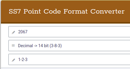
ITU International point codes are 14 bits long, and format is described as 3-8-3. The 3-8-3 form of Point code just means the 14 bit long point code is broken up into three sections, the first section is made up of the first 3 bits, the second section is made up of the next 8 bits then the remaining 3 bits in the last section, for a total of 14 bits.
So our 14 bit 3-8-3 Point Code looks like this in binary form:
If you’re dealing with multiple vendors or products,you’ll see some SS7 Point Codes represented as decimal (2067), some showing as 1-2-3 codes and sometimes just raw binary. Fun hey?
So why does the binary part matter? Well the answer is for masks.
To loop back to the start of this post, we talked about IP routing using a network address and netmask, to represent a range of IP addresses. We can do the same for SS7 Point Codes, but that requires a teeny bit of working out.
As an example let’s imagine we need to setup a route to all point codes from 3-4-0 through to 3-6-7, without specifying all the individual point codes between them.
Firstly let’s look at our start and end point codes in binary:
100-00000100-000 = 3-004-0 (Start Point Code)
100-00000110-111 = 3-006-7 (End Point Code)
Looking at the above example let’s look at how many bits are common between the two,
100-00000100-000 = 3-004-0 (Start Point Code)
100-00000110-111 = 3-006-7 (End Point Code)
The first 9 bits are common, it’s only the last 5 bits that change, so we can group all these together by saying we have a /9 mask.
When it comes time to add a route, we can add a route to 3-4-0/9 and that tells our STP to match everything from point code 3-4-0 through to point code 3-6-7.
The STP doing the routing it only needs to match on the first 9 bits in the point code, to match this route.
SS7 Routing Tables
Now we have covered Masking for roues, we can start putting some routes into our network.
In order to get a message from one point code to another point code, where there isn’t a direct linkset between the two, we need to rely on routing, which is performed by our STPs.
This is where all that point code mask stuff we just covered comes in.
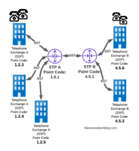
Let’s look at a diagram below,
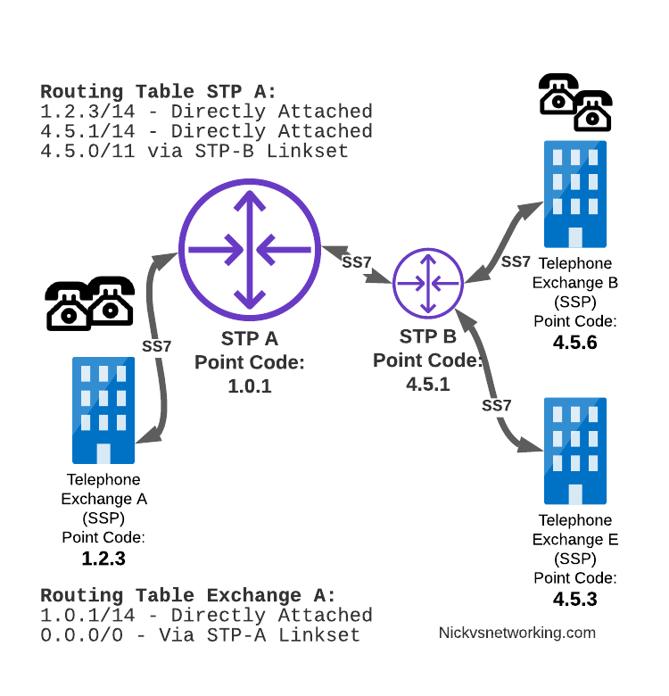
Let’s look at the routing to get a message from Exchange A (SSP) on the bottom left of the picture to Exchange E (SSP) with Point Code 4.5.3 in the bottom right of the picture.
Exchange A (SSP) on the bottom left of the picture has point code 1.2.3 assigned to it and a Linkset to STP-A. It has the implicit route to STP-A as it’s got that linkset, but it’s also got a route configured on it to reach any other point code via the Linkset to STP-A via the 0.0.0/0 route which is the SS7 equivalent of a default route. This means any traffic to any point code will go to STP-A.
From STP-A we have a linkset to STP-B. In order to route to the point codes behind STP-B, STP-A has a route to match any Point Code starting with 4.5.X, which is 4.5.0/11. This means that STP-A will route any Point Code between 4.5.1 and 4.5.7 down the Linkset to STP-B.
STP-B has got a direct connection to Exchange B and Exchange E, so has implicit routes to reach each of them.
So with that routing table, Exchange A should be able to route a message to Exchange E.
But…
Return Routing
Just like in IP routing, we need return routing. while Exchange A (SSP) at 1.2.3 has a route to everywhere in the network, the other parts of the network don’t have a route to get to it. This means a request from 1.2.3 can get anywhere in the network, but it can’t get a response back to 1.2.3.
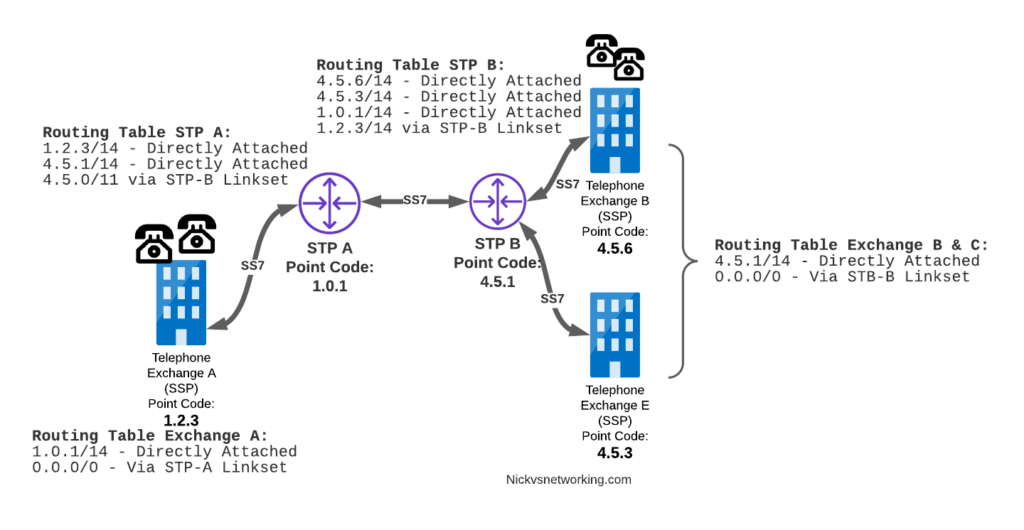
So to get traffic back to Exchange A (SSP) at 1.2.3, our two Exchanges on the right (Exchange B & C with point codes 4.5.6 and 4.5.3) will need routes added to them. We’ll also need to add routes to STP-B, and once we’ve done that, we should be able to get from Exchange A to any point code in this network.
There is a route missing here, see if you can pick up what it is!
So we’ve added a default route via STP-B on Exchange B & Exchange E, and added a route on STP-B to send anything to 1.2.3/14 via STP-A, and with that we should be able to route from any exchange to any other exchange.
One last point on terminology – when we specify a route we don’t talk in terms of the next hop Point Code, but the Linkset to route it down. For example the default route on Exchange A is 0.0.0/0 via STP-A linkset (The linkset from Exchange A to STP-A), we don’t specify the point code of STP-A, but just the name of the Linkset between them.
Back into the Lab
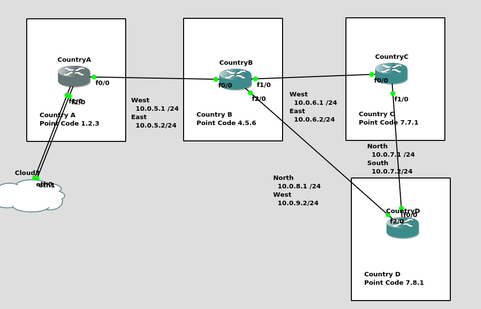
So back to the lab, where we left it was with linksets between each point code, so each Country could talk to it’s neighbor.
Let’s confirm this is the case before we go setting up routes, then together, we’ll get a route from Country A to Country C (and back).
So let’s check the status of the link from Country B to its two neighbors – Country A and Country C. All going well it should look like this, and if it doesn’t, then stop by my last post and check you’ve got everything setup.
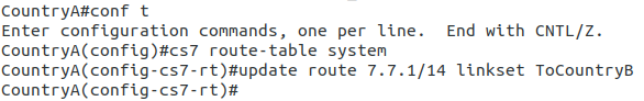
So let’s add some routing so Country A can reach Country C via Country B. On Country A STP we’ll need to add a static route. For this example we’ll add a route to 7.7.1/14 (Just Country C).
That means Country A knows how to get to Country C. But with no return routing, Country C doesn’t know how to get to Country A. So let’s fix that.
We’ll add a static route to Country C to send everything via Country B.
CountryC#conf t
Enter configuration commands, one per line.  End with CNTL/Z.
CountryC(config)#cs7 route-table system
CountryC(config)#update route 0.0.0/0 linkset ToCountryB
*Jan 01 05:37:28.879: %CS7MTP3-5-DESTSTATUS: Destination 0.0.0 is accessible
So now from Country C, let’s see if we can ping Country A (Ok, it’s not a “real” ICMP ping, it’s a link state check message, but the result is essentially the same).
By running:
CountryC# ping cs7 1.2.3
*Jan 01 06:28:53.699: %CS7PING-6-RTT: Test Q.755 1.2.3: MTP Traffic test rtt 48/48/48
*Jan 01 06:28:53.699: %CS7PING-6-STAT: Test Q.755 1.2.3: MTP Traffic test 100% successful packets(1/1)
*Jan 01 06:28:53.699: %CS7PING-6-RATES: Test Q.755 1.2.3: Receive rate(pps:kbps) 1:0 Sent rate(pps:kbps) 1:0
*Jan 01 06:28:53.699: %CS7PING-6-TERM: Test Q.755 1.2.3: MTP Traffic test terminated.
We can confirm now that Country C can reach Country A, we can do the same from Country A to confirm we can reach Country B.
But what about Country D? The route we added on Country A won’t cover Country D, and to get to Country D, again we go through Country B.
This means we could group Country C and Country D into one route entry on Country A that matches anything starting with 7-X-X,
For this we’d add a route on Country A, and then remove the original route;
Of course, you may have already picked up, we’ll need to add a return route to Country D, so that it has a default route pointing all traffic to STP-B. Once we’ve done that from Country A we should be able to reach all the other countries:
CountryA#show cs7 route
Dynamic Routes 0 of 1000

Routing table = system Destinations = 3 Routes = 3

Destination            Prio Linkset Name        Route
---------------------- ---- ------------------- -------
4.5.6/14         acces   1  ToCountryB          avail
7.0.0/3          acces   5  ToCountryB          avail


CountryA#ping cs7 7.8.1
*Jan 01 07:28:19.503: %CS7PING-6-RTT: Test Q.755 7.8.1: MTP Traffic test rtt 84/84/84
*Jan 01 07:28:19.503: %CS7PING-6-STAT: Test Q.755 7.8.1: MTP Traffic test 100% successful packets(1/1)
*Jan 01 07:28:19.503: %CS7PING-6-RATES: Test Q.755 7.8.1: Receive rate(pps:kbps) 1:0  Sent rate(pps:kbps) 1:0
*Jan 01 07:28:19.507: %CS7PING-6-TERM: Test Q.755 7.8.1: MTP Traffic test terminated.
CountryA#ping cs7 7.7.1
*Jan 01 07:28:26.839: %CS7PING-6-RTT: Test Q.755 7.7.1: MTP Traffic test rtt 60/60/60
*Jan 01 07:28:26.839: %CS7PING-6-STAT: Test Q.755 7.7.1: MTP Traffic test 100% successful packets(1/1)
*Jan 01 07:28:26.839: %CS7PING-6-RATES: Test Q.755 7.7.1: Receive rate(pps:kbps) 1:0  Sent rate(pps:kbps) 1:0
*Jan 01 07:28:26.843: %CS7PING-6-TERM: Test Q.755 7.7.1: MTP Traffic test terminated.
So where to from here?
Well, we now have a a functional SS7 network made up of STPs, with routing between them, but if we go back to our SS7 network overview diagram from before, you’ll notice there’s something missing from our lab network…
So far our network is made up only of STPs, that’s like building a network only out of routers!
In our next lab, we’ll start adding some SSPs to actually generate some SS7 traffic on the network, rather than just OAM traffic.
SMS by default uses the GSM-7 bit alphabet, thanks to the fact each letter is only 7 bits long, this means you can cram 160 characters into a 140 byte message body.
However, this 7-bit alphabet is, well, limited, because it’s 7 bits long it means we can only have 128 different combinations of these bits, or to put it another way, with only 128 different unique combinations of these bits, we can only define 128 characters.
You have the standard 26 latin alphabet characters that Sesame Street drilled into you, some characters with accents, digits, and a limited set of symbols.
The GSM 7 bit alphabet does not include is character sets and symbols common for non-English written languages.
Shift Tables
To deal with this 3GPP introduced “National Language Shift Tables”, which are enable a sort of find-and-replace approach to the 7-bit alphabet, where certain characters that are unused in one alphabet, take the value of characters from the local alphabet.
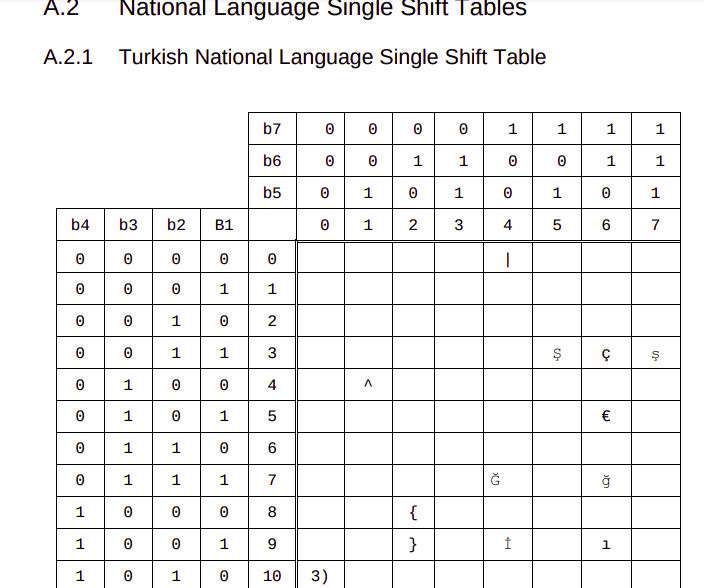
So if you want to send the character Ğ (Found in the Turkish and Azerbaijani alphabets) you’d select the Turkish language Shift table, that replaces the capital G (71) with Ğ.
Of course you need to have two things to do this, you need the Language Shift Table to tell you what local-language letters replace what default letters, and a mechanism to state that you’re using a language shift table.
3GPP define the National Language Shift tables in TS 23.038, where you can lookup the character you want to encode, so you know what 7 bit value it uses, for example our character Ğ is 1000111 in the 7-bit alphabet.
Next we need to indicate that we don’t want 1000111 in the 7-bit alphabet to be rendered as “G”, we want to use the “Turkish National Language Single Shift Table” which will render it as “Ğ”. We do this in the User Data Header of the SMS Body, the same way we’d indicate that an SMS is a concatenated SMS.
But by adding a header in the User Data Header of the SMS Body, we eat into the space we can use to send the message body, with a single User Data Header indicating that the Turkish National Language Single Shift Table is being used, we go from a maximum of 160 characters without the User Data Header, to 134 characters.
I’ve shared a lot more information on the User Data Header in this post on Concatenated SMS, should you be interested.
No matter how many shift tables you define, you’re not going to cover all of these in a 7-bit alphabet.
So all this encoding falls to 💩 when someone adds an Emoji.
The “😀” Emoji, represented as U+1F600 in Unicode, can be encoded as 0xF09F9880 in UTF-8 or 0xD83DDE00 in UTF-16.
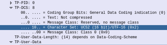
So in 3GPP Networks, when you need more than 128 characters to work with, and when shift tables won’t cut the mustard, you can change the encoding used to use the International Standards Organisations’ “Universal coded character set 2” (UCS-2).
Unfortunately UCS-2 never really took off, but luckily it overlaps with UTF-16 character set, which is a lot more common.
So if you’ve got a “😀” Emoji in your SMS body the encoding of the message will be changed from GSM-7 to use a different encoding -UTF-16 / UCS2.
SMS Body showing TP-DCS character set is UCS2 / UTF-16 as Emojis are present
There’s a catch here, if you’re moving from a 7-bit alphabet to a 16 bit alphabet, you’re going to have a lot less space to work with.
A single SMS contains 1120 bits for the user data (The actual message).
With GSM-7 bit encoding, each letter takes up 7 bits, so 1120÷7 gives us 160 characters.
With UTF-16/UCS2 encoding, each letter takes up 16 bits so 1120÷16 only give us 70 characters.
So what happens next?
Often when Emojis are used, as our message is now limited to 70 characters concatenated messages are used, which takes a further 8 bytes of our message body if concatenated messages are used, further limiting the message length.
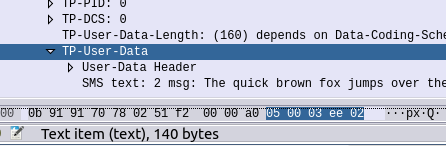
Most people think of 160 characters as the length of an SMS. But the payload is actually 140 bytes, but with better encoding 1 character doesn’t require 1 byte.
The above paragraph is exactly 160 characters. It would fit into a standard SMS.
By using the GSM 7 bit alphabet, you can cram 16 characters into 140 bytes (octets) of space, which is kind of cool.
140 bytes of data containing 160 characters of text
You’d think if you took a 160 character SMS, and concatenated it onto another 160 character SMS, you’d get a total of 320 characters, right (160+160=320)? Alas it’s not that simple.
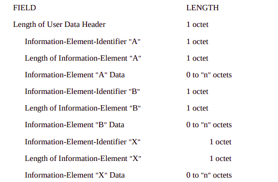
In order to achieve the concatenation of messages in a way that’s transparent to the users (rather than a series of SMSes coming through one-after-the-ther) a User-Data Header (TP-User-Data-Header-Indicator aka TP-UHDI) is added to the TP-User Data of the TPDU (the part that actually contains the user message).
This User-Data Header takes up 7 bytes, which with GSM encoding robs us of 6 characters from the message length. (Not a typo, GSM7 encoding does not mean 1 character = 1 byte, hence we can get 160 characters into 140 bytes of space) So a two SMS concatenated message would only allow 268 characters to be sent (134 characters + 134 characters).
Let’s take a look at this header that’s robbing us of message length, but enabling us to concatenate messages.
For starters, the information about how many parts in the concatenated message, and what part number this one is, is located in the message body, hence robbing us of characters.
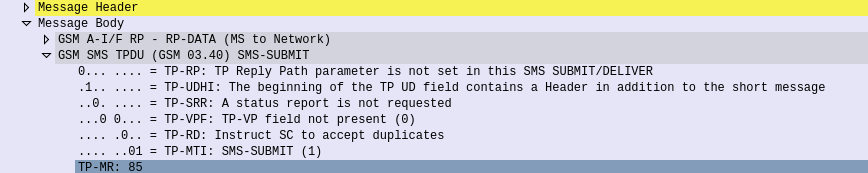
But we only know about the presence of this header being in the message body because the SMS-SUBMIT TPDU has the TP-UDHI flag (TP-User-Data-Header-Indicator) set, so we know the User Data is prefixed with the User-Data-Header.
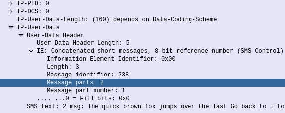
Now if we have a look in the TP-User-Data we can see the User-Data Header, this can actually carry a few different payloads, but in our case, it’s carrying the Concatenated Short Messages IE, which tells us the message identifier (unique per single-but-multi-part message, the number of parts in the message (in this case 2) and the part number this is (part 1 of 2).
First part of a two part SMS
Now the phone has indicated this is a multipart message, the length of the data is still 160, but the length of the actual message is now limited to 134 characters with GSM7 encoding.
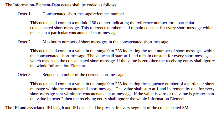
The encoding isn’t as bad as you might expect: 1st byte indicates the total length of the User Data Headers (After this the actual user data begins), 2nd byte is the IE identifier, for Concatenated Short Messages, this is 00, 3rd byte is the length of the Concatenated Short Messages IE, 4th byte is the message identifier in hex, 5th byte is the number of message parts in hex (So up to 255 message parts) 6th byte is the message part number, to aid in putting it back together in order.
3GPP TS 23.040 – 9.2.3.24 TP-User Data (TP-UD) – Encoding of User Data Header and generic IEConcatenated short message IE encoding
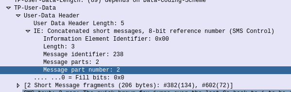
So what we end up with is a header inside our user payload, advising that this is a concatenated SMS, the message identifier, the number of parts in the message, and the part number of this particular message.
Last part of two part SMS
The SMSc on receipt of these has to spool them back out to the destination with the same message part number, and same headers in place.
The phone receiving the SMS has to wait for all the parts to come through and then reassemble before rendering to the user.
So that’s how concatenated SMS works. While this may seem convoluted and silly in a world where transfering more than 140 bytes of data is trivial, SMS was introduced in the early 1990s, and in theory at least, a user with a phone that supported SMS purchased when SMS was introduced, should still be able to interwork with phones today.
We’ve covered SMS in the past, but MMS is a different kettle of fish.
Let’s look at how the call flow goes, when Bob wants to send a picture to Alice.
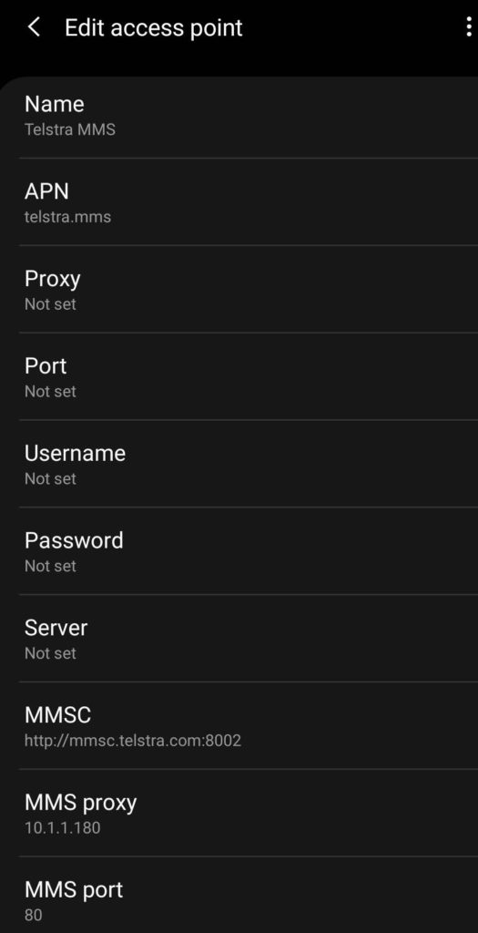
Before Bob sends the MMS, his phone will have to be setup with the correct settings to send MMS. Sometimes this is done manually, for others it’s done through the Carrier provisioning SMS that preloads the settings, and for others it’s baked in based on the Android Carrier settings XML,
APN settings for Telstra in Australia for MMS
It’s made up of the APN to send MMS traffic over, the MMSC address (Multimedia Message Switching Center) and often an MMS proxy and port combination for where the traffic will actually go.
Message Flow – Bob to MMSC (Mobile Originated MMS)
Bob opens his phone, creates a new message to Alice, selects the picture (or other multimedia filetype) to send to her and hits the send button.
For starters, MMS has a file size limit, like MTU it’s not advertised, so you don’t know if you’ve hit it, so rather like MTU is a “lowest has the highest success of getting through” rule. So Bob’s phone will most likely scale the image down to fit inside 300K.
Next Bob’s phone knows it has an MMS to send, for this is opens up a new bearer on the MMS APN, typically called MMS, but configured in the phone by Bob.
Why use a separate APN for sending 300K of MMS traffic? Once upon a time mobile data was expensive. By having a separate APN just for MMS traffic (An APN that could do nothing except send / receive MMS) allowed easier billing / tariffing of data, as MMS traffic was sent over a APN which was unmetered.
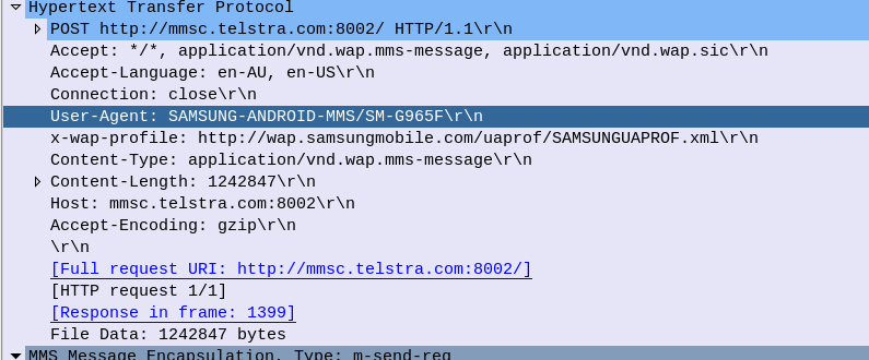
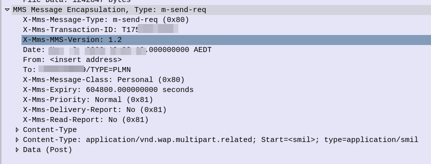
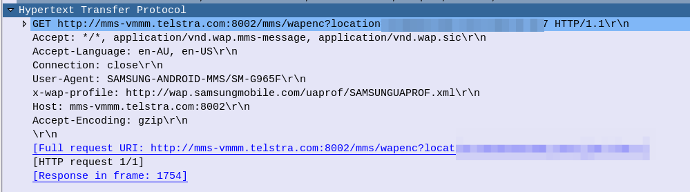
After the bearer is setup on the MMS APN, Bob’s phone begins crafting a HTTP 1.1 Post to be sent to the MMSC. The content type of this request will be application/vnd.wap.mms-message and the body of the HTTP post will be made up of MMS Message Encapsulation, with the body containing the picture he wants to send to Alice.
Note: Historically Wireless Session Protocol (WSP) was used in lieu of HTTP. These clients would now need a WAP gateway to translate into HTTP.
This HTTP Post is then sent to the MMSC Address, or, if present, the MMSC Proxy address. This traffic is sent over the MMS APN that we just brought up.
HTTP POST Headers for the MO MMS MessageMMS Message Encapsulation from MO MMS Message
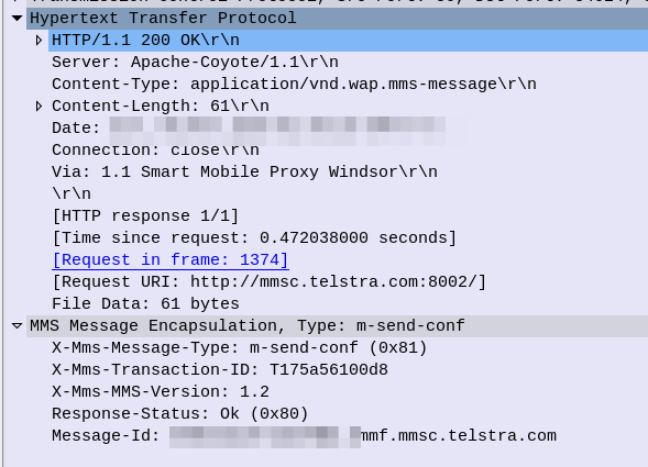
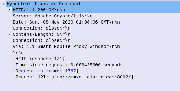
The MMSC receives this information, and then, if all was successful, responds with a 200 OK,
200 OK response to MO MMS Message
So now the MMSC has the information from Bob, let’s flip over to Alice.
Message Flow – MMSC to Alice (Mobile Terminated MMS)
For the purposes of simplicity, we’re going to rule out the MMSC from doing clever things like converting the media, accepting email (SMPP) as MMS, etc, etc. Instead we’re going to assume Alice and Bob are on the same Network, and our MMSC is just doing store-and-forward.
The MMSC will look at the To address in the MMS Message Encapsulation of the request Bob sent, to determine that this message is destined for Alice.
The MMSC will load the media content (photo) sent by Bob destined for Alice and serve it via HTTP. The MMSC generates a random URL to serve it this particular file on, with each MMS the MMSC handles being assigned a random URL containing the media content.
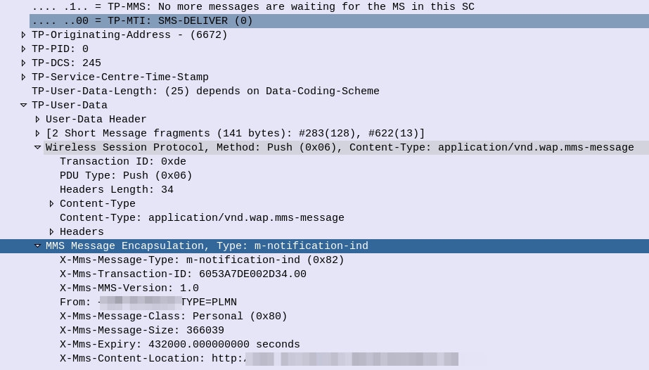
Next the MMSC will need to tell Alice’s phone, that she has an MMS waiting for her. This is done by generating an SMS to send to Alice’s phone,
The user-data of this SMS is the Wireless Session Protocol with the method PUSH – Aka WAP Push.
SMS alerting the user of an MMS waiting for delivery
This specially encoded SMS is parsed by the Alice’s phone, which tells the her there is an MMS message waiting for her.
On some operating systems this is pulled automatically, on others, users need to select “Download” to actually get the file.
The UE then just runs an HTTP get to the address in the X-Mms-Content-Location: Header to pull the multimedia content that Bob sent.
HTTP GET from Alice’s Phone / UE to retrieve MMS sent by Bob (MT-MMS)
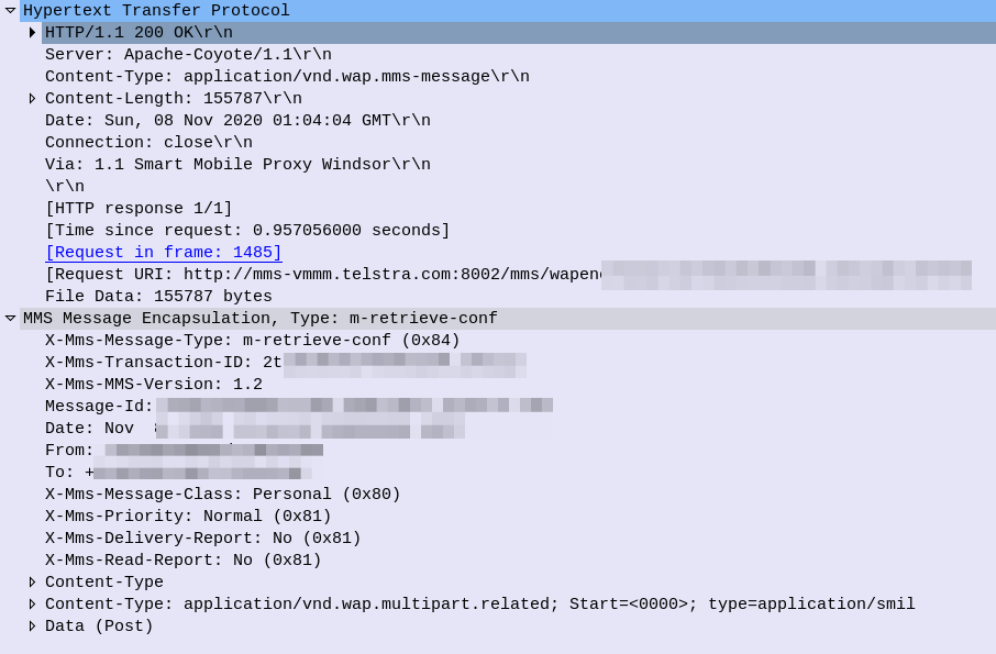
All going well the URL is valid and Alice’s phone retrieves the message, getting a 200 OK back from the server with the message content.
HTTP Response (200 OK) for MT-MMS, sent by the MMSC to Alice’s phone with the MMS Body
So now Alice’s phone has the MMS content and renders it on the screen, Alice can see the Photo Bob sent her.
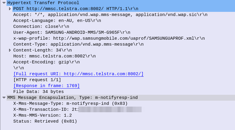
Lastly Alice’s phone sends a HTTP POST again to the MMSC, this time indicating the message status is “Retrieved”,
And to close everything off the MMSC confirms receipt of the Retrieved status with a 200 OK, and we are done.
What didn’t we cover?
So that’s a basic MMS message flow, but there’s a few parts we didn’t cover.
The overall architecture beyond just the store-and forward behaviour, charging and authentication we didn’t cover. So let’s look at each of these points.
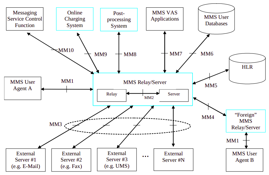
Overall Architecture
What we just covered what what’s defined as the MM1 interface.
There’s obviously a stack of other interfaces, such as for charging, messaging between MMSC/Carriers, subscriber locating / user database, etc.
Charging
MMSCs would typically have a connection to trigger charging events / credit-control events prior to processing the message.
For online charging the Ro interface can be used, as you would for IMS charging events.
3GPP 3GPP TS 32.270 covers the charging architecture for online/offline charging for MMS.
Authentication
Unfortunately authentication was a bit of an afterthought for the MMS standard, and can be done several different ways.
The most common is to correlate the IP Address on the MMS APN against a subscriber.
Network Slicing, is a new 5G Technology. Or is it?
Pre 3GPP Release 16 the capability to “Slice” a network already existed, in fact the functionality was introduced way back at the advent of GPRS, so what is so new about 5G’s Network Slicing?
Network Slice: A logical network that provides specific network capabilities and network characteristics
3GPP TS 123 501 / 3 Definitions and Abbreviations
Let’s look at the old and the new ways, of slicing up networks, pre release 16, on LTE, UMTS and GSM.
Old Ways: APN Separation
The APN or “Access Point Name” is used so the SGSN / MME knows which gateway to that subscriber’s traffic should be terminated on when setting up the session.
APN separation is used heavily by MVNOs where the MVNO operates their own P-GW / GGSN. This allows the MNVO can handle their own rating / billing / subscriber management when it comes to data. A network operator just needs to setup their SGSN / MME to point all requests to setup a bearer on the MVNO’s APN to the MNVO’s gateways, and presoto, it’s no longer their problem.
Later as customers wanted MPLS solutions extended over mobile (Typically LTE), MNOs were able to offer “private APNs”. An enterprise could be allocated an APN by the MNO that would ensure traffic on that APN would be routed into the enterprise’s MPLS VRF. The MNO handles the P-GW / GGSN side of things, adding the APN configuration onto it and ensuring the traffic on that APN is routed into the enterprise’s VRF.
Different QCI values can be assigned to each APN, to allow some to have higher priority than others, but by slicing at an APN level you lock all traffic to those QoS characteristics (Typically mobile devices only support one primary APN used for routing all traffic), and don’t have the flexibility to steer which networks which traffic from a subscriber goes to.
It’s not really practical for everyone to have their own APNs, due in part to the namespace limitations, the architecture of how this is usually done limits this, and the simple fact of everyone having to populate an APN unique to them would be a real headache.
5G replaces APNs with “DNNs” – Data Network Names, but the functionality is otherwise the same.
In Summary: APN separation slices all traffic from a subscriber using a special APN and provide a bearer with QoS/QCI values set for that APN, but does not allow granular slicing of individual traffic flows, it’s an all-or-nothing approach and all traffic in the APN is treated equally.
The old Ways: Dedicated Bearers
Dedicated bearers allow traffic matching a set rule to be provided a lower QCI value than the default bearer. This allows certain traffic to/from a UE to use GBR or Non-GBR bearers for traffic matching the rule.
The rule itself is known as a “TFT” (Traffic Flow Template) and is made up of a 5 value Tuple consisting of IP Source, IP Destination, Source Port, Destination Port & Protocol Number. Both the UE and core network need to be aware of these TFTs, so the traffic matching the TFT can get the QCI allocated to it.
This can be done a variety of different ways, in LTE this ranges from rules defined in a PCRF or an external interface like those of an IMS network using the Rx interface to request a dedicated bearers matching the specified TFTs via the PCRF.
Unlike with 5G network slicing, dedicated bearers still traverse the same network elements, the same MME, S-GW & P-GW is used for this traffic. This means you can’t “locally break out” certain traffic.
In Summary: Dedicated bearers allow you to treat certain traffic to/from subscribers with different precedence & priority, but the traffic still takes the same path to it’s ultimate destination.
This means one eNodeB can broadcast more than one PLMN and server more than one mobile network.
This slicing is very coarse – it allows two operators to share the same eNodeBs, but going beyond a handful of PLMNs on one eNB isn’t practical, and the PLMN space is quite limited (1000 PLMNs per country code max).
In Summary: MOCN allows slicing of the RAN on a very coarse level, to slice traffic from different operators/PLMNs sharing the same RAN.
Its use is focused on sharing RAN rather than slicing traffic for users.
Since the beginning of time, SIP has used the 2xx responses to confirm all went OK.
If you thought sending an SMS in a VoLTE/IMS network would see a 2xx OK response and then that’s the end of it, you’d be wrong.
So let’s take a look into sending SMS over VoLTE/IMS networks!
So our story starts with the Subscriber sending an SMS, which generate a SIP MESSAGE.
The Content-Type of this SIP MESSAGE is set to application/vnd.3gpp.sms rather than Text, and that’s because SMS over IMS uses the Short Message Transfer Protocol (SM-TP) inherited from GSM.
The Short Message Transfer Protocol (SM-TP) (Not related to Simple Message Transfer Protocol used in Email clients) is made up of Transfer Protocol Data Units (TPDU) that contain our message information, even though we have the Destination in our SIP headers, it’s again defined in the SM-TP body.
At first this may seem like a bit of duplication, but this allows older SMS Switching Centers (SMSc) to add support for IMS networks without any major changes, just what the SM-TP payload is wrapped up in changes.
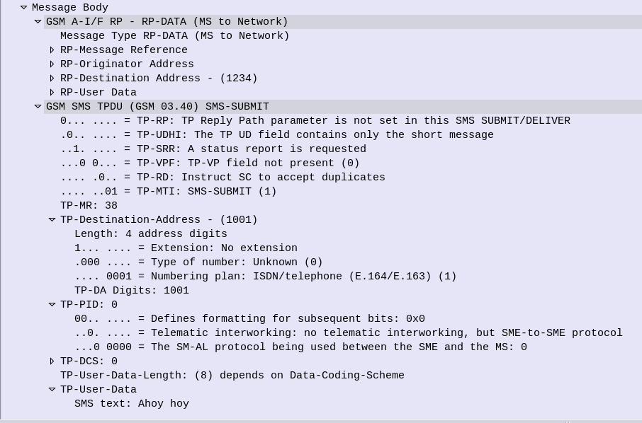
SIP MESSAGE Request Body encoded in SM-TP
So back to our SIP MESSAGE request, typed out by the Subscriber, the UE sends this a SIP MESSAGE onto our IMS Network.
The IMS network follows it’s IFCs and routing rules, and makes it to the termination points for SMS traffic – the SMSc.
The SMSc sends back either a 200 OK or a 202 Accepted, and you’d think that’s the end of it, but no.
Our Subscriber still sees “Sending” on the screen, and the SMS is not shown as sent yet.
Instead, when the SMS has been delivered or buffered, relayed, etc, the SMSc generates a new SIP request, (as in new Call-ID / Dialog) with the request type MESSAGE, addressed to the Subscriber.
The payload of this request is another application/vnd.3gpp.sms encoded request body, again, containing SM-TP encoded data.
When the UE receives this, it will then consider the message delivered.
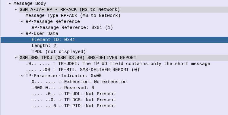
SM-TP encoded Delivery Report
Of course things change slightly when delivery reports are enabled, but that’s another story!
Ok, admittedly I haven’t actually seen “When a Stranger Calls”, or the less popular sequel “When a stranger Redials” (Ok may have made the last one up).
But the premise (as I read Wikipedia) is that the babysitter gets the call on the landline, and the police trace the call as originating from the landline.
But you can’t phone yourself, that’s not how local loops work – When the murderer goes off hook it loops the circuit, which busys it. You could apply ring current to the line I guess externally but unless our murder has a Ring generator or has setup a PBX inside the house, the call probably isn’t coming from inside the house.
On Topic – The GMLC
The GMLC (Gateway Mobile Location Centre) is a central server that’s used to locate subscribers within the network on different RATs (GSM/UMTS/LTE/NR).
The GMLC typically has interfaces to each of the radio access technologies, there is a link between the GMLC and the CS network elements (used for GSM/UMTS) such as the HLR, MSC & SGSN via Lh & Lg interfaces, and a link to the PS network elements (LTE/NR) via Diameter based SLh and SLg interfaces with the MME and HSS.
The GMLC’s tentacles run out to each of these network elements so it can query them as to a subscriber’s location,
LTE Call Flow
To find a subscriber’s location in LTE Diameter based signaling is used, to query the MME which in turn queries, the eNodeB to find the location.
But which MME to query?
The SLh Diameter interface is used to query the HSS to find out which MME is serving a particular Subscriber (identified by IMSI or MSISDN).
The LCS-Routing-Info-Request is sent by the GMLC to the HSS with the subscriber identifier, and the LCS-Routing-Info-Response is returned by the HSS to the GMLC with the details of the MME serving the subscriber.
Now we’ve got the serving MME, we can use the SLgDiameter interface to query the MME to the location of that particular subscriber.
The MME can report locations to the GMLC periodically, or the GMLC can request the MME provide a location at that point. For the GMLC to request a subscriber’s current location a Provide-Location-Request is set by the GMLC to the MME with the subscriber’s IMSI, and the MME responds after querying the eNodeB and optionally the UE, with the location info in the Provide-Location-Response.
(I’m in the process of adding support for these interfaces to PyHSS and all going well will release some software shortly to act at a GMLC so people can use this.)
Finding the actual Location
There are a few different ways the actual location of the UE is determined,
At the most basic level, Cell Global Identity (CGI) gives the identity of the eNodeB serving a user. If you’ve got a 3 sector site each sector typically has its own Cell Global Identity, so you can determine to a certain extent, with the known radiation pattern, bearing and location of the sector, in which direction a subscriber is. This happens on the network side and doesn’t require any input from the UE. But if we query the UE’s signal strength, this can then be combined with existing RF models and the signal strength reported by the UE to further pinpoint the user with a bit more accuracy. (Uplink and downlink cell coverage based positioning methods) Barometric pressure and humidity can also be reported by the base station as these factors will impact resulting signal strengths.
Timing Advance (TA) and Time of Arrival (TOA) both rely on timing signals to/from a UE to determine it’s distance from the eNodeB. If the UE is only served by a single cell this gives you a distance from the cell and potentially an angle inside which the subscriber is. This becomes far more useful with 3 or more eNodeBs in working range of the UE, where you can “triangulate” the UE’s location. This part happens on the network side with no interaction with the UE. If the UE supports it, EUTRAN can uses Enhanced Observed Time Difference (E-OTD) positioning method, which does TOD calcuation does this in conjunction with the UE.
GPS Assisted (A-GPS) positioning gives good accuracy but requires the devices to get it’s current location using the GPS, which isn’t part of the baseband typically, so isn’t commonly implimented.
Uplink Time Difference of Arrival (UTDOA) can also be used, which is done by the network.
So why do we need to get Subscriber Locations?
The first (and most noble) use case that springs to mind is finding the location of a subscriber making a call to emergency services. Often upon calling an emergency services number the GMLC is triggered to get the subscriber’s location in case the call is cut off, battery dies, etc.
But GMLCs can also be used for lots of other purposes, marketing purposes (track a user’s location and send targeted ads), surveillance (track movements of people) and network analytics (look at subscriber movement / behavior in a specific area for capacity planning).
Different countries have different laws regulating access to the subscriber location functions.
Hack to disable Location Reporting on Mobile Networks
If you’re wondering how you can disable this functionality, you can try the below hack to ensure that your phone does not report your location.
Press the power button on your phone
Turn it off
In reality, no magic super stealth SIM cards, special phones or fancy firmware will prevent the GMLC from finding your location. So far none of the “privacy” products I’ve looked at have actually done anything special at the Baseband level. Most are just snakeoil.
For as long as your device is connected to the network, the passive ways of determining location, such as Uplink Time Difference of Arrival (UTDOA) and the CGI are going to report your location.
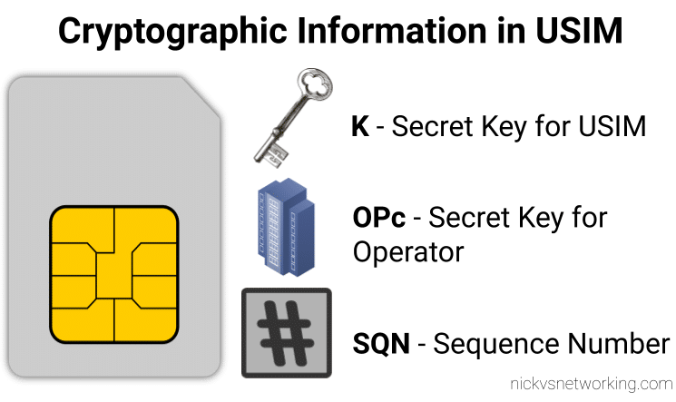
While we’ve already covered the inputs required by the authentication elements of the core network (The HSS in LTE/4G, the AuC in UMTS/3G and the AUSF in 5G) to generate an output, it’s worth noting that the Confidentiality Algorithms used in the process determines the output.
This means the Authentication Vector (Also known as an F1 and F1*) generated for a subscriber using Milenage Confidentiality Algorithms will generate a different output to that of Confidentiality Algorithms XOR or Comp128.
To put it another way – given the same input of K key, OPc Key (or OP key), SQN & RAND (Random) a run with Milenage (F1 and F1* algorithm) would yield totally different result (AUTN & XRES) to the same inputs run with a simple XOR.
Technically, as operators control the network element that generates the challenges, and the USIM that responds to them, it is an option for an operator to implement their own Confidentiality Algorithms (Beyond just Milenage or XOR) so long as it produced the same number of outputs. But rolling your own cryptographic anything is almost always a terrible idea.
So what are the differences between the Confidentiality Algorithms and which one to use? Spoiler alert, the answer is Milenage.
Milenage
Milenage is based on AES (Originally called Rijndael) and is (compared to a lot of other crypto implimentations) fairly easy to understand,
AES is very well studied and understood and unlike Comp128 variants, is open for anyone to study/analyse/break, although AES is not without shortcomings, it’s problems are at this stage, fairly well understood and mitigated.
There are a few clean open source examples of Milenage implementations, such as this C example from FreeBSD.
XOR
It took me a while to find the specifications for the XOR algorithm – it turns out XOR is available as an alternate to Milenage available on some SIM cards for testing only, and the mechanism for XOR Confidentiality Algorithm is only employed in testing scenarios, not designed for production.
Instead of using AES under the hood like Milenage, it’s just plan old XOR of the keys.
Comp128 was originally a closed source algorithm, with the maths behind it not publicly available to scrutinise. It is used in GSM A3 and A5 functions, akin to the F1 and F1* in later releases.
Due to its secretive nature it wasn’t able to be studied or analysed prior to deployment, with the idea that if you never said how your crypto worked no one would be able to break it. Spoiler alert; public weaknesses became exposed as far back as 1998, which led to Toll Fraud, SIM cloning and eventually the development of two additional variants, with the original Comp128 renamed Comp128-1, and Comp128-2 (stronger algorithm than the original addressing a few of its flaws) and Comp128-3 (Same as Comp128-2 but with a 64 bit long key generated).
In our last post we covered the file system structure of a smart card and the basic concepts of communication with cards. In this post we’ll look at what happens on the application layer, and how to interact with a card.
For these examples I’ll be using SIM cards, because admit it, you’ve already got a pile sitting in a draw, and this is a telco blog after all. You won’t need the ADM keys for the cards, we’ll modify files we’ve got write access to by default.
Commands & Instructions
So to do anything useful with the card we need issue commands / instructions to the card, to tell it to do things. Instructions like select this file, read it’s contents, update the contents to something else, verify my PIN, authenticate to the network, etc.
The term Command and Instruction are used somewhat interchangeably in the spec, I realise that I’ve done the same here to make it just as confusing, but instruction means the name of the specific command to be called, and command typically means the APDU as a whole.
The “Generic Commands” section of 3GPP TS 31.101 specifies the common commands, so let’s take a look at one.
The creatively named SELECT command/instruction is used to select the file we want to work with. In the SELECT command we’ll include some parameters, like where to find the file, so some parameters are passed with the SELECT Instruction to limit the file selection to a specific area, etc, the length of the file identifier to come, and the identifier of the file.
The card responds with a Status Word, returned by the card, to indicate if it was successful. For example if we selected a file that existed and we had permission to select, we’d get back a status word indicating the card had successfully selected the file. Status Words are 2 byte responses that indicate if the instruction was successful, but also the card has data it wants to send to the terminal as a result of the instruction, how much data the terminal should expect.
So if we just run a SELECT command, telling the card to select a file, we’ll get back a successful response from the card with a data length. Next need to get that data from the card. As the card can’t initiate communication, the GET RESPONSE instruction is sent to the card to get the data from the card, along with the length of the data to be returned.
The GET RESPONSE instruction/command is answered by the card with an APDU containing the data the card has to send, and the last 2 bytes contain the Status Word indicating if it was successful or not.
APDUs
So having covered the physical and link layers, we now move onto the Application Layer – where the magic happens.
Smart card communications is strictly master-slave based when it comes to the application layer.
The terminal sends a command to the card, which in turn sends back a response. Command -> Response, Command -> Response, over and over.
These commands are contained inside APplication Data Units (APDUs).
So let’s break down a simple APDU as it appears on the wire, so to speak.
The first byte of our command APDU is taken up with a header called the class byte, abbreviated to CLA. This specifies class coding, secure messaging options and channel options.
In the next byte we specify the Instruction for the command, that’s the task / operation we want the card to perform, in the spec this is abbreviated to INS.
The next two bytes, called P1 & P2 (Parameter 1 & Parameter 2) specify the parameters of how the instruction is to be to be used.
Next comes Lc – Length of Command, which specifies the length of the command data to follow,
Datacomes next, this is instruction data of the length specified in Lc.
Finally an optional Le – Length of expected response can be added to specify how long the response from the card should be.
Crafting APDUs
So let’s encode our own APDU to send to a card, for this example we’ll create the APDU to tell the card to select the Master File (MF) – akin to moving to the root directory on a *nix OS.
For this we’ll want a copy of ETSI TS 102 221 – the catchily named “Smart cards; UICC-Terminal interface; Physical and logical characteristics” which will guide in the specifics of how to format the command, because all the commands are encoded in hexadecimal format.
So here’s the coding for a SELECT command from section 11.1.1.1 “SELECT“,
For the CLA byte in our example we’ll indicate in our header that we’re using ISO 7816-4 encoding, with nothing fancy, which is denoted by the byte A0.
For the next but we’ve got INS (Instruction) which needs to be set to the hex value for SELECT, which is represented by the hex value A4, so our second byte will have that as it’s value.
The next byte is P1, which specifies “Selection Control”, the table in the specification outlines all the possible options, but we’ll use 00 as our value, meaning we’ll “Select DF, EF or MF by file id”.
The next byte P2 specifies more selection options, we’ll use “First or only occurrence” which is represented by 00.
The Lc byte defines the length of the data (file id) we’re going to give in the subsequent bytes, we’ve got a two byte File ID so we’ll specify 2 (represented by 02).
Finally we have the Data field, where we specify the file ID we want to select, for the example we’ll select the Master File (MF) which has the file ID ‘3F00‘, so that’s the hex value we’ll use.
So let’s break this down;
Code
Meaning
Value
CLA
Class bytes – Coding options
A0 (ISO 7816-4 coding)
INS
Instruction (Command) to be called
A4 (SELECT)
P1
Parameter 1 – Selection Control (Limit search options)
00 (Select by File ID)
P2
Parameter 1 – More selection options
00 (First occurrence)
Lc
Length of Data
02 (2 bytes of data to come)
Data
File ID of the file to Select
3F00 (File ID of master file)
So that’s our APDU encoded, it’s final value will be A0 A4 00 00 02 3F00
So there we have it, a valid APDU to select the Master File.
In the next post we’ll put all this theory into practice and start interacting with a real life SIM cards using PySIM, and take a look at the APDUs with Wireshark.
The pins on the terminal / card reader are arranged so that when inserting a card, the ground contact is the first contact made with the reader, this clever design consideration to protect the card and the reader from ESD damage.
Operating Voltages
When Smart Cards were selected for use in GSM for authenticating subscribers, all smart cards operated at 5v. However as mobile phones got smaller, the operating voltage range became more limited, the amount of space inside the handset became a premium and power efficiency became imperative. The 5v supply for the SIM became a difficult voltage to provide (needing to be buck-boosted) so lower 3v operation of the cards became a requirement, these cards are referred to as “Class B” cards. This has since been pushed even further to 1.8v for “Class C” cards.
If you found a SIM from 1990 it’s not going to operate in a 1.8v phone, but it’s not going to damage the phone or the card.
The same luckily goes in reverse, a card designed for 1.8v put into a phone from 1990 will work just fine at 5v.
This is thanks to the class flag in the ATR response, which we’ll cover later on.
Clocks
As we’re sharing one I/O pin for TX and RX, clocking is important for synchronising the card and the reader. But when smart cards were initially designed the clock pin on the card also served as the clock for the micro controller it contained, as stable oscillators weren’t available in such a tiny form factor. Modern cards implement their own clock, but the clock pin is still required for synchronising the communication.
I/O Pin
The I/O pin is used for TX & RX between the terminal/phone/card reader and the Smart Card / SIM card. Having only one pin means the communications is half duplex – with the Terminal then the card taking it in turns to transmit.
Reset Pin
Resets the card’s communications with the terminal.
Filesystem
So a single smart card can run multiple applications, the “SIM” is just an application, as is USIM, ISIM and any other applications on the card.
These applications are arranged on a quasi-filesystem, with 3 types of files which can be created, read updated or deleted. (If authorised by the card.)
Because the file system is very basic, and somewhat handled like a block of contiguous storage, you often can’t expand a file – when it is created the required number of bytes are allocated to it, and no more can be added, and if you add file A, B and C, and delete file B, the space of file B won’t be available to be used until file C is deleted.
This is why if you cast your mind back to when contacts were stored on your phone’s SIM card, you could only have a finite number of contacts – because that space on the card had been allocated for contacts, and additional space can no longer be allocated for extra contacts.
So let’s take a look at our 3 file types:
MF (Master File)
The MF is like the root directory in Linux, under it contains all the files on the card.
DF (Dedciated File)
An dedicated file (DF) is essentially a folder – they’re sometimes (incorrectly) referred to as Directory Files (which would be a better name).
They contain one or more Elementary Files (see below), and can contain other DFs as well.
Dedicated Files make organising the file system cleaner and easier. DFs group all the relevant EFs together. 3GPP defines a dedicated file for Phonebook entries (DFphonebook), MBMS functions (DFtv) and 5G functions (DF5gs).
We also have ADFs – Application Dedicated Files, for specific applications, for example ADFusim contains all the EFs and DFs for USIM functionality, while ADFgsm contains all the GSM SIM functionality.
The actual difference with an ADF is that it’s not sitting below the MF, but for the level of depth we’re going into it doesn’t matter.
DFs have a name – an Application Identifier (AID) used to address them, meaning we can select them by name.
EF (Elementary File)
Elementary files are what would actually be considered a file in Linux systems.
Like in a Linux file systems EFs can have permissions, some EFs can be read by anyone, others have access control restrictions in place to limit who & what can access the contents of an EF.
There are multiple types of Elementary Files; Linear, Cyclic, Purse, Transparent and SIM files, each with their own treatment by the OS and terminal.
Most of the EFs we’ll deal with will be Transparent, meaning they ##
ATR – Answer to Reset
So before we can go about working with all our files we’ll need a mechanism so the card, and the terminal, can exchange capabilities.
There’s an old saying that the best thing about standards is that there’s so many to choose, from and yes, we’ve got multiple variants/implementations of the smart card standard, and so the card and the terminal need to agree on a standard to use before we can do anything.
This is handled in a process called Answer to Reset (ATR).
When the card is powered up, it sends it’s first suggestion for a standard to communicate over, if the terminal doesn’t want to support that, it just sends a pulse down the reset line, the card resets and comes back with a new offer.
If the card offers a standard to communicate over that the terminal does like, and does support, the terminal will send the first command to the card via the I/O line, this tells the card the protocol preferences of the terminal, and the card responds with it’s protocol preferences. After that communications can start.
Basic Principles of Smart Cards Communications
So with a single I/O line to the card, it kind of goes without saying the communications with the card is half-duplex – The card and the terminal can’t both communicate at the same time.
Instead a master-slave relationship is setup, where the smart card is sent a command and sends back a response. Command messages have a clear ending so the card knows when it can send it’s response and away we go.
Like most protocols, smart card communications is layered.
At layer 1, we have the physical layer, defining the operating voltages, encoding, etc. This is standardised in ISO/IEC 7816-3.
Above that comes our layer 2 – our Link Layer. This is also specified in ISO/IEC 7816-3, and typically operates in one of two modes – T0 or T1, with the difference between the two being one is byte-oriented the other block-oriented. For telco applications T0 is typically used.
Our top layer (layer 7) is the application layer. We’ll cover the details of this in the next post, but it carries application data units to and from the card in the form of commands from the terminal, and responses from the card.
Coming up Next…
In the next post we’ll look into application layer communications with cards, the commands and the responses.
I know a little bit about SIM cards / USIM cards / ISIM Cards. Enough to know I don’t know very much about them at all.
So throughout this series of posts of unknown length, I’ll try and learn more and share what I’m learning, citing references as much as possible.
So where to begin? I guess at the start,
A supposedly brief history of Smart Cards
There are two main industries that have driven the development and evolution of smart cards – telecom & banking / finance, both initially focused on the idea that carrying cash around is unseemly.
This planet has – or rather had – a problem, which was this: most of the people living on it were unhappy for pretty much of the time. Many solutions were suggested for this problem, but most of these were largely concerned with the movement of small green pieces of paper, which was odd because on the whole it wasn’t the small green pieces of paper that were unhappy.
Douglas Adams – The Hitchhiker’s Guide to the Galaxy
When the idea of Credit / Debit Cards were first introduced the tech was not electronic, embossed letters on the card were fed through that clicky-clacky-transfer machine (Google tells me this was actually called the “credit card imprinter”) and the card details imprinted onto carbon copy paper.
Customers wanted something faster, so banks delivered magnetic strip cards, where the card data could be read even more quickly, but as the security conscious of you will be aware, storing data on magnetic strips on a card to be read by any reader, allows them to be read by any reader, and therefore duplicated really easily, something the banks quickly realised.
To combat this, card readers typically would have a way to communicate back to a central bank computer. The central computer verified the PIN entered by the customer was correct, confirmed that the customer had enough money in their balance for the transaction and it wasn’t too suspicious. This was, as you would imagine in the late 1980’s early 1990’s, rather difficult to achieve. A reliable (and cheap) connection back to a central bank computer wasn’t always a given, nor instant, and so this was still very much open to misuse.
“Carders” emmerged, buying/selling/capturing credit card details, and after programming a blank card with someone else’s fraudulently obtained card details, could write them on a blank card before going on a spending spree for a brief period of time. Racking up a giant debt that wasn’t reconciled against the central computer until later, when the card was thrown away and replaced with another.
I know what you’re thinking – I come to this blog for ramblings about Telecommunications, not the history of the banking sector. So let’s get onto telco;
The telecom sector faced similar issues, at the time mobile phones were in their infancy, and so Payphones were how people made calls when out and about.
A phone call from a payphone in Australia has sat at about $0.40 for a long time, not a huge amount, but enough you’d always want to be carrying some change if you wanted to make calls. Again, an inconvenience for customers as coins are clunky, and an inconvenience for operators as collecting the coins from tens of thousands of payphones is expensive.
Telcos around the world trailed solutions, including cards with magnetic strips containing the balance of the card, but again people quickly realised that you could record the contents of the magnetic stripe data of the card when it had a full balance, use all the balance on the card, and then write back the data you stored earlier with a full balance.
So two industries each facing the same issue: it’s hard to securely process payments offline in a way that can’t be abused.
Enter the smart card – a tiny computer in a card that the terminal (Payphone or Credit Card Reader) interacts with, but the card is very much in charge.
When used in a payphone, the caller inserts the smart card and dials the number, and dialog goes something like this (We’ll assume Meter Pulses are 40c worth):
Payphone: “Hey SmartCard, how much credit do you have on you?”
Smart Card: “I have $1.60 balance”
*Payphone ensures card has enough credit for the first meter pulse, and begins listening for Meter Pulses*
*When a meter pulse received:*
Payphone: “Please deduct $0.40 from your Balance”
Smart Card: “Ok, you have $1.20 remaining”
This process repeats for each meter pulse (Payphone metering is a discussion for another day) until all the credit has been used / Balance is less than 1 meter pulse charge.
While anyone could ask the smart card “Hey SmartCard, how much credit do you have on you?” it would only return the balance, and if you told the smart card “I used $1 credit, please deduct it” like the payphone did, you’d just take a dollar off the credit stored on the card.
Saying “Hey SmartCard set the balance to $1,000,000” would result in a raised eyebrow from the SmartCard who rejects the request.
After all – It’s a smart card. It has the capability to do that.
So in the telecom sector single use smart cards were rolled out, programmed in the factory with a set dollar value of credit, sold at that dollar value and thrown away when depleted.
The banking industry saw even more potential, balance could be stored on the card, and the PIN could be verified by the card, the user needs to know the correct PIN, as does the smart card, but the terminal doesn’t need to know this, nor does it need to talk back to a central bank computer all the time, just every so often so the user gets the bill.
It worked much the same way, although before allowing a deduction to be made from the balance of the card, a user would have to enter their PIN which was verified by the card before allowing the transaction.
Eventually these worlds collided (sort of), both wanting much the same thing from smart cards. So the physical characteristics, interface specs (rough ones) and basic communications protocol was agreed on, and what eventually became ISO/IEC 7816 was settled upon.
Any card could be read by any terminal, and it was up to the systems implementer (banks and telecos initially) what data the card did and what the terminal did.
Active RFID entered the scene and there wasn’t even a need for a physical connection to the card, but the interaction was the same. We won’t really touch on the RFID side, but all of this goes for most active RFID cards too.
Enter Software
Now the card was a defined standard all that was important really was the software on the card. Banks installed bank card software on their cards, while telcos installed payphone card software on theirs.
But soon other uses emerged, ID cards could provide a verifiable and (reasonably) secure way to verify the card’s legitimacy, public transport systems could store commuter’s fares on the card, and vending machines, time card clocks & medical records could all jump on the bandwagon.
These were all just software built on the smart card platform.
Hello SIM Cards
A early version Smart card was used in the German C-Netz cellular network, which worked in “mobile” phones and also payphones, to authenticate subscribers.
After that the first SIM cards came into the public sphere in 1991 with GSM as a way to allow a subscriber’s subscription to be portable between devices, and this was standardised by ETSI to become the SIM cards still used in networks using GSM, and evolved into the USIM used in 3G/4G/5G networks.
Names of Smart Cards & Readers
To make life a bit easier I thought I’d collate all the names for smart cards and readers that are kind of different but used interchangeably depending on the context.
Smart Card
|
Terminal
UICC (Universal Integrated Circuit Card) – Standards name for Smart Card
Card Reader (Generic)
SIM (Mobile Telco application running on UICC)
Phone (Telco)
USIM (Mobile Telco application running on UICC)
SIM Slot (Telco)
Credit / Debit / EFTPOS Card (Banking)
UE (Telco)
Java Card (Type of Smart Card OS)
EFTPOS Terminal (Banking)
Phone Card (Telco / Payphone)
And then…
From here we’ll look at various topics:
Introduction to Smart Cards (This post)
Meet & Greet (The basics of Smart Cards & their File System)
APDUs and Hello Card (How terminals interact with a smart cards)
(Interacting with real life cards using Smart Card readers and SIM cards)
Mixing It Up (Changing values on Cards)
Other topics we may cover are Javacard and Global Platform, creating your own smart card applications, a deeper look at the different Telco apps like SIM/USIM/ISIM, OTA Updates for cards / Remote File Management (RFM), and developing for SimToolkit.
In our last Osmocom post we talked about the basics of packet data, and configuring our BTSs to support it.
In this post we’ll take a look at using Osmocom’s Serving Gateway Support Node (SGSN) named OsmoSGSN.
At the BSC traffic is divided into two categories, Circuit Switched (CS) traffic (Like voice calls & SMS) which is handed by the MSC, and Packet Switched (PS) traffic (Mobile data) is handled by the SGSN.
The SGSN acts as an anchor point for our packet data, it connects our BSC (that handles our RAN) to the GGSN (that handles the connection to external data networks).
Although it’s not technically possible to run a data only 2G/3G network (you require the MSC) it almost could be. The SGSN handles authentication of subscribers, and runs the PS network completely standalone from the CS network. The SGSN does it’s own handover management, authentication, etc, without any connection to the MSC.
Basic SGSN Config
Like the previous Osmocom network elements we’ve covered, we’ll access the SGSN via Telnet on localhost (the server running the Osmocom stack) on port 4254.
Once we’ve accessed the terminal we’ll escalate our privileges using the enable command, and run configure terminal to start configuring,
We’ll begin by setting the local IP our SGSN will listen on, the gtp local-ip, we’ll need this to be externally accessible for our BTSs, so set it to the IP of the server.
sgsn
  gtp local-ip 10.0.1.201
Next we’ll need to configure the IP of our GGSN. It gets a bit messy if we’re running everything on one box, as we’re going to have the SGSN and the GGSN trying to communicate on the same ports for GTP, so best to assign an IP in the loopback range, like 127.0.0.2 in my case, for the GGSN:
We can also steer GGSN selection based on the APN, for example an APN for a corporate network, you may want to have a dedicated GGSN for, for example, we could create a second GGSN – GGSN 1 and route any traffic on our “special.access.net” APN to that GGSN, and everything else to GGSN0:
You may notice that APNs look like domain names – that’s because they can be,
If we owned the domain special.access.net we could set it to resolve to the GGSN IP we’re using for the special.access.net GGSN at 10.0.1.99, and instead of hardcoding the IP in our config use a DNS server (like 8.8.8.8) to resolve these.
To learn more about setting up compression and encryption of the data, take a look in the Osmo-SGSN Manual.
Charging
Charging in mobile networks is a topic we could spend weeks on, but we’re not going to!
OsmoSGSN implements a simple CDR based charging mechanism that writes to a text file a simple CSV file with most importantly the IMSI and bytes in / out for each subscriber, that can be used to implement offline charging (Post paid) if required, and with some hacky scripts can even cut off sessions after reaching a certain amount of throughput (online charging aka pre-paid).
By adding the below to our config OsmoSGSN will write CDRs into /home/nick/sgsn.cdr every 60 seconds.
These antennas claimed to operate on 900/1800/2100MHz and this time had the correct connector (SMA not RP-SMA)…
I ordered two of these antennas for the princely sum of $3 and hooked them onto the NanoVNA to analyse the antennas – the poor man’s Anritsu SiteMaster!
I was operating the GSM network using ARFCN 871 with the SDR which translates to 1782 MHz for Uplink and 1877 MHz for Downlink, so I plugged in the values into the VNA to take a look at how it performs in those ranges,
Performance is actually pretty on point,
On the Uplink frequency we’ve got a VSWR of 1.15 which is about as good as it gets,
And in the downlink we’ve got a VSWR of 1.221, still pretty good.
Performance on the remainder of the 1800MHz band is pretty decent, with clear drops in VSWR where the Uplink and Downlink channels lie.
I measured the full band for Uplink on the 1800Mhz band (1710Mhz – 1785Mhz):
Analysis of Uplink Bands
Which shows not all channels are created equal, if you were looking for real performance on these antennas and not just playing, you’d probably want to put your uplink channel on one of the frequencies shown by the marker,
And the full band for Downlink on the 1800Mhz band (1805Mhz – 1890Mhz):
Again, varied performance, but the peaks and troughs line up on the uplink and downlink, so a lower ARFCN in the 1800Mhz band would put you about on the red marker for both,
Comparing the output of each of the antennas I’ve got
In reality I could be using a bent coat hanger for an antenna, the signals shouldn’t be able to leave the room, but it’s a good excuse to use the toys!