Tag Archives: USIM

Tales from the Trenches: The issue with Emergency Calling URNs in IMS Networks

A lot of countries have a single point of contact for emergency services; in Europe you’d call 112 in an emergency, 000 in Australia or 911 in the US. Calling this number in the country will get you the emergency services.

This means a caller can order an ambulance for smoke inhalation, and the fire brigade, in one call.

But that’s not the case in every country; many countries don’t have one number for the emergency services, they’ve got multiple; a phone number for police, a different number for fire brigade and a different number for an ambulance.

For example, in Brazil if you need the police, you call 190, while a for example, uses 193 as the emergency number for the fire department, the police can be reached at 190 or 191 depending on if it’s road policing or general, and medical emergencies are covered by 192. Other countries have similar setups.

This is all well and good if you’re in Brazil, and you call 192 for an ambulance, the phone sends a SIP INVITE with a Request URI of sip:[email protected], because we can put a rule into our E-CSCF to say if the number is 192 to route it to the answer point for ambulances – But that’s not often the case on emergency calls.

In IMS, handsets generally detect the number dialed is on the Emergency Calling Code (ECC) list from the USIM Card.

The use of the ECC list means the phone knows this is an emergency call, and this is really important. For countries that use AML this can trigger sending of the AML SMS that process, and Emergency Calls should always be allowed to be made, even without credit, a valid SIM card, or even a SIM in the phone at all.

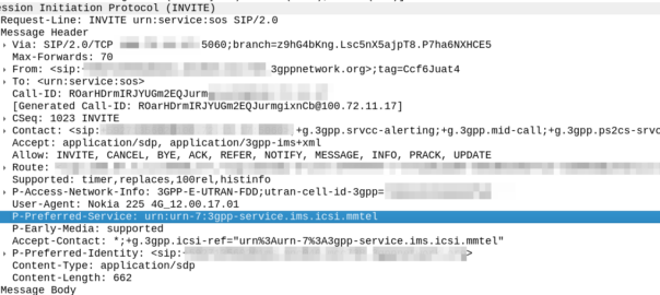
But this comes with a cost; when a user dials 911, the phones doesn’t (generally) send a call to sip:[email protected] like it would with any other dialled number, but rather the SIP INVITE is sent to urn:service:sos which will be routed to the PSAP by the E-CSCF. When a call comes through to these URNs they’re given top priority in the network

This is all well and good in a country where it doesn’t matter which emergency service you called, because all emergency calls route to a single PSAP, but in a country with multiple numbers, it’s really important when you call and ambulance, your call doesn’t get routed to animal control.

That means the phone has to look at what emergency number you’ve dialed, and map the URN it sends the call to to match what you’ve actually requested.

Recently we’ve been helping an operator in a country with a numbering plan like this, and we’ve been finding the limits of the standards here.
So let’s start by looking at what the standards state:

IMS Emergency Calling is governed by TS 103.479 which in turn delegates to IETF RFC 5031, but for the calling number to URN translation, it’s pretty quiet.

Let’s look at what RFC 5031 allows for URNs:

  • urn:service:sos.ambulance
  • urn:service:sos.animal-control
  • urn:service:sos.fire
  • urn:service:sos.gas
  • urn:service:sos.marine
  • urn:service:sos.mountain
  • urn:service:sos.physician
  • urn:service:sos.poison
  • urn:service:sos.police

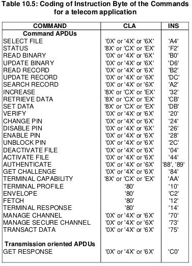
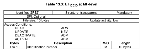
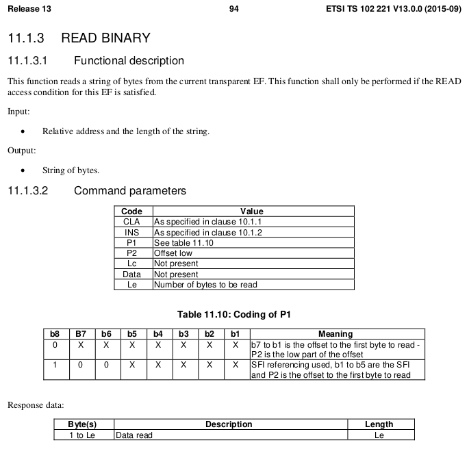
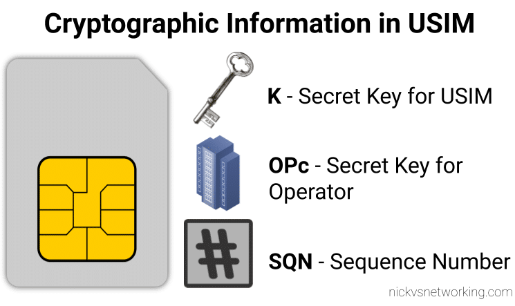
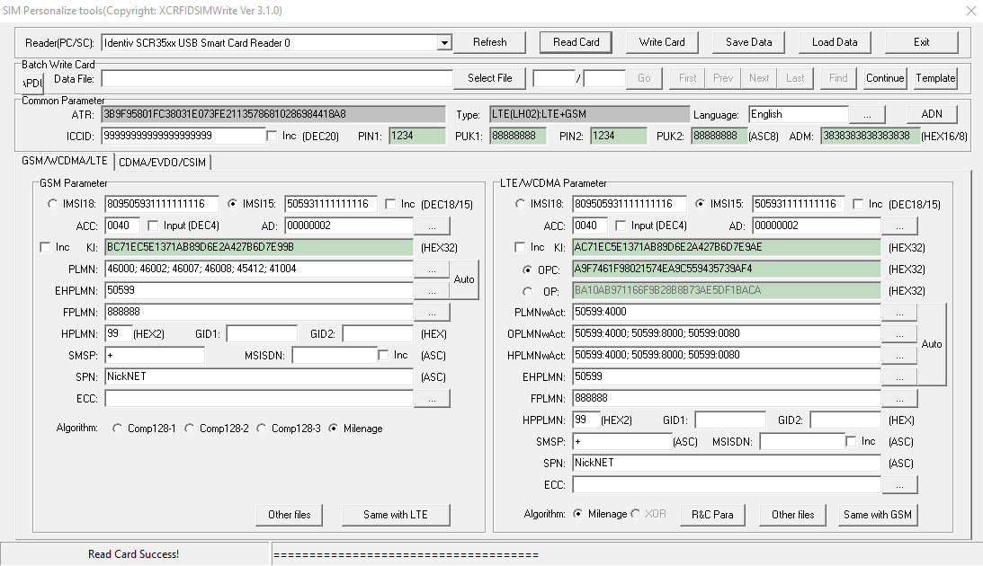
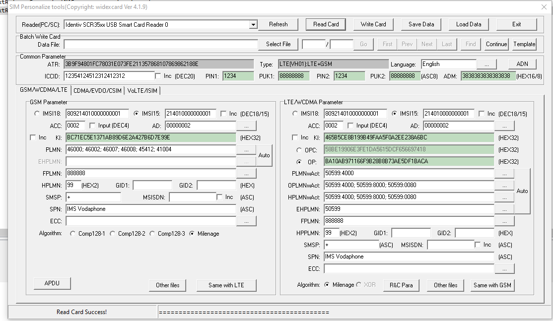
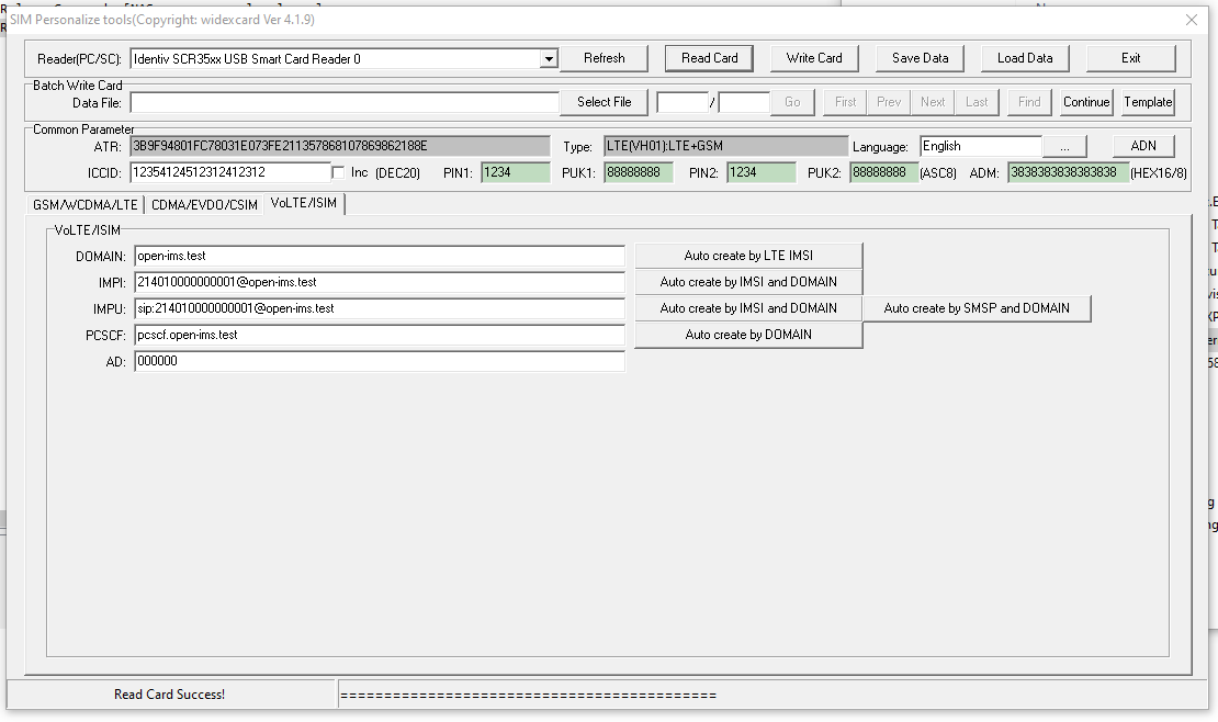
The USIM’s Emergency Calling Codes EF would be the perfect source of this data; for each emergency calling code defined, you’ve got a flag to indicate what it’s for, here’s what we’ve got available on the SIM Card:

  • Bit 1 Police
  • Bit 2 Ambulance
  • Bit 3 Fire Brigade
  • Bit 4 Marine Guard
  • Bit 5 Mountain Rescue
  • Bit 6 manually initiated eCall
  • Bit 7 automatically initiated eCall
  • Bit 8 is spare and set to “0”

So these could be mapped pretty easily you’d think, so if the call is made to an Emergency Calling Code flagged with Bit 4, the URN would go to urn:service:sos.mountain.

Alas from our research, we’ve found most OEMs send calls to the generic urn:service:sos, regardless of the dialled number and the ECC flags that are set on the SIM for that number.

One of the big chip vendors sends calls to an ECC flagged as Ambulance to urn:service:sos.fire, which is totally infuriating, and we’ve had to put a rule in our E-CSCF to handle this if the User Agent is set to one of their phones.

Is there room for improvement here? For sure! Emergency calling is super important, and time is of the essence, while animal control can probably transfer you to an ambulance, an emergency is by very nature time sensitive, and any time wasted can lead to worse outcomes.

While carrier bundles from the OEMs can handle this, the global ability to take any phone, from any country and call an emergency number is so important, that relying on a country-by-country approach here won’t suffice.

What could we do as an industry to address this?

Acknowledging that not all countries have a single point of contact for emergency service, introducing a simple mechanism in the UE SIP message to indicate what number (Emergency Calling Code) the user actually dialled would be invaluable here.

URNs are important, but knowing the dialed number when it comes to PSAP routing, is so important – This wouldn’t even need to be its own SIP header, it could just be thrown into the Contact header as another parameter.

Highly developed markets are often the first to embrace new tech (for us this means VoLTE and VoNR), but this means that these issues seen by less developed markets won’t appear until long after the standard has been set in stone, and often countries like this aren’t at the table of the standards bodies to discuss such requirements.

This easy, reasonable update to the standard, has the potential to save lives, and next time this comes up in a working group I’ll be advocating for a change.

SIM / Smart Card Deep Dive – Part 4 – Interacting with Cards IRL

This is part 3 of an n part tutorial series on working with SIM cards.

So in our last post we took a whirlwind tour of what an APDU does, is, and contains.

Interacting with a card involves sending the APDU data to the card as hex, which luckily isn’t as complicated as it seems.

While reading what the hex should look like on the screen is all well and good, actually interacting with cards is the name of the game, so that’s what we’ll be doing today, and we’ll start to abstract some of the complexity away.

Getting Started

To follow along you will need:

  • A Smart Card reader – SIM card / Smart Card readers are baked into some laptops, some of those multi-card readers that read flash/SD/CF cards, or if you don’t have either of these, they can be found online very cheaply ($2-3 USD).
  • A SIM card – No need to worry about ADM keys or anything fancy, one of those old SIM cards you kept in the draw because you didn’t know what to do with them is fine, or the SIM in our phone if you can find the pokey pin thing. We won’t go breaking anything, promise.

You may end up fiddling around with the plastic adapters to change the SIM form factor between regular smart card, SIM card (standard), micro and nano.

USB SIM / Smart Card reader supports all the standard form factors makes life a lot easier!

To keep it simple, we’re not going to concern ourselves too much with the physical layer side of things for interfacing with the card, so we’ll start with sending raw APDUs to the cards, and then we’ll use some handy libraries to make life easier.

PCSC Interface

To abstract away some complexity we’re going to use the industry-standard PCSC (PC – Smart Card) interface to communicate with our SIM card. Throughout this series we’ll be using a few Python libraries to interface with the Smart Cards, but under the hood all will be using PCSC to communicate.

pyscard

I’m going to use Python3 to interface with these cards, but keep in mind you can find similar smart card libraries in most common programming languages.

At this stage as we’re just interfacing with Smart Cards, our library won’t have anything SIM-specific (yet).

We’ll use pyscard to interface with the PCSC interface. pyscard supports Windows and Linux and you can install it using PIP with:

pip install pyscard

So let’s get started by getting pyscard to list the readers we have available on our system:

#!/usr/bin/env python3
from smartcard.System import *
print(readers())

Running this will output a list of the readers on the system:

Here we can see the two readers that are present on my system (To add some confusion I have two readers connected – One built in Smart Card reader and one USB SIM reader):

(If your device doesn’t show up in this list, double check it’s PCSC compatible, and you can see it in your OS.)

So we can see when we run readers() we’re returned a list of readers on the system.

I want to use my USB SIM reader (The one identified by Identiv SCR35xx USB Smart Card Reader CCID Interface 00 00), so the next step will be to start a connection with this reader, which is the first in the list.

So to make life a bit easier we’ll store the list of smart card readers and access the one we want from the list;

#!/usr/bin/env python3
from smartcard.System import *
r = readers()
connection = r[0].createConnection()
connection.connect()

So now we have an object for interfacing with our smart card reader, let’s try sending an APDU to it.

Actually Doing something Useful

Today we’ll select the EF that contains the ICCID of the card, and then we will read that file’s binary contents.

This means we’ll need to create two APDUs, one to SELECT the file, and the other to READ BINARY to get the file’s contents.

We’ll set the instruction byte to A4 to SELECT, and B0 to READ BINARY.

Table of Instruction bytes from TS 102 221

APDU to select EF ICCID

The APDU we’ll send will SELECT (using the INS byte value of A4 as per the above table) the file that contains the ICCID.

Each file on a smart card has been pre-created and in the case of SIM cards at least, is defined in a specification.

For this post we’ll be selecting the EF ICCID, which is defined in TS 102 221.

Information about EF-ICCID from TS 102 221

To select it we will need it’s identifier aka File ID (FID), for us the FID of the ICCID EF is 2FE2, so we’ll SELECT file 2FE2.

Going back to what we learned in the last post about structuring APDUs, let’s create the APDU to SELECT 2FE2.

CodeMeaningValue
CLAClass bytes – Coding optionsA0 (ISO 7816-4 coding)
INSInstruction (Command) to be calledA4 (SELECT)
P1Parameter 1 – Selection Control (Limit search options)00 (Select by File ID)
P2Parameter 1 – More selection options04 (No data returned)
LcLength of Data 02 (2 bytes of data to come)
DataFile ID of the file to Select2FE2 (File ID of ICCID EF)

So that’s our APDU encoded, it’s final value will be A0 A4 00 04 02 2FE2

So let’s send that to the card, building on our code from before:

#!/usr/bin/env python3
from smartcard.System import *
from smartcard.util import *
r = readers()
connection = r[0].createConnection()
connection.connect()

print("Selecting ICCID File")
data, sw1, sw2 = connection.transmit(toBytes('00a40004022fe2'))
print("Returned data: " + str(data))
print("Returned Status Word 1: " + str(sw1))
print("Returned Status Word 2: " + str(sw2))

If we run this let’s have a look at the output we get,

We got back:

Selecting ICCID File
 Returned data: []
 Returned Status Word 1: 97
 Returned Status Word 2: 33

So what does this all mean?

Well for starters no data has been returned, and we’ve got two status words returned, with a value of 97 and 33.

We can lookup what these status words mean, but there’s a bit of a catch, the values we’re seeing are the integer format, and typically we work in Hex, so let’s change the code to render these values as Hex:

#!/usr/bin/env python3
from smartcard.System import *
from smartcard.util import *
r = readers()
connection = r[0].createConnection()
connection.connect()

print("Selecting ICCID File")
data, sw1, sw2 = connection.transmit(toBytes('00a40004022fe2'))
print("Returned data: " + str(data))
print("Returned Status Word 1: " + str(hex(sw1)))
print("Returned Status Word 2: " + str(hex(sw2)))

Now we’ll get this as the output:

Selecting ICCID File
Returned data: []
Returned Status Word 1: 0x61
Returned Status Word 2: 0x1e

So what does this all mean?

Well, there’s this handy website with a table to help work this out, but in short we can see that Status Word 1 has a value of 61, which we can see means the command was successfully executed.

Status Word 2 contains a value of 1e which tells us that there are 30 bytes of extra data available with additional info about the file. (We’ll cover this in a later post).

So now we’ve successfully selected the ICCID file.

Keeping in mind with smart cards we have to select a file before we can read it, so now let’s read the binary contents of the file we selected;

The READ BINARY command is used to read the binary contents of a selected file, and as we’ve already selected the file 2FE2 that contains our ICCID, if we run it, it should return our ICCID.

If we consult the table of values for the INS (Instruction) byte we can see that the READ BINARY instruction byte value is B0, and so let’s refer to the spec to find out how we should format a READ BINARY instruction:

CodeMeaningValue
CLAClass bytes – Coding optionsA0 (ISO 7816-4 coding)
INSInstruction (Command) to be calledB0 (READ BINARY)
P1Parameter 1 – Coding / Offset00 (No Offset)
P2Parameter 2 – Offset Low00
LeHow many bytes to read0A (10 bytes of data to come)

We know the ICCID file is 10 bytes from the specification, so the length of the data to return will be 0A (10 bytes).

Let’s add this new APDU into our code and print the output:

#!/usr/bin/env python3
from smartcard.System import *
from smartcard.util import *
r = readers()
connection = r[0].createConnection()
connection.connect()

print("Selecting ICCID File")
data, sw1, sw2 = connection.transmit(toBytes('00a40000022fe2'))
print("Returned data: " + str(data))
print("Returned Status Word 1: " + str(hex(sw1)))
print("Returned Status Word 2: " + str(hex(sw2)))

And we have read the ICCID of the card.

Phew.

That’s the hardest thing we’ll need to do over.

From now on we’ll be building the concepts we covered here to build other APDUs to get our cards to do useful things. Now you’ve got the basics of how to structure an APDU down, the rest is just changing values here and there to get what you want.

In our next post we’ll read a few more files, write some files and delve a bit deeper into exactly what it is we are doing.

Want more? 
You can also get the weekly posts on the blog by Connecting on LinkedIn, following me on Twitter, or Subscribing via RSS.

SIM / Smart Card Deep Dive – Part 3 – APDUs and Hello Card

In our last post we covered the file system structure of a smart card and the basic concepts of communication with cards. In this post we’ll look at what happens on the application layer, and how to interact with a card.

For these examples I’ll be using SIM cards, because admit it, you’ve already got a pile sitting in a draw, and this is a telco blog after all. You won’t need the ADM keys for the cards, we’ll modify files we’ve got write access to by default.

Commands & Instructions

So to do anything useful with the card we need issue commands / instructions to the card, to tell it to do things. Instructions like select this file, read it’s contents, update the contents to something else, verify my PIN, authenticate to the network, etc.

The term Command and Instruction are used somewhat interchangeably in the spec, I realise that I’ve done the same here to make it just as confusing, but instruction means the name of the specific command to be called, and command typically means the APDU as a whole.

The “Generic Commands” section of 3GPP TS 31.101 specifies the common commands, so let’s take a look at one.

The creatively named SELECT command/instruction is used to select the file we want to work with. In the SELECT command we’ll include some parameters, like where to find the file, so some parameters are passed with the SELECT Instruction to limit the file selection to a specific area, etc, the length of the file identifier to come, and the identifier of the file.

The card responds with a Status Word, returned by the card, to indicate if it was successful. For example if we selected a file that existed and we had permission to select, we’d get back a status word indicating the card had successfully selected the file. Status Words are 2 byte responses that indicate if the instruction was successful, but also the card has data it wants to send to the terminal as a result of the instruction, how much data the terminal should expect.

So if we just run a SELECT command, telling the card to select a file, we’ll get back a successful response from the card with a data length. Next need to get that data from the card. As the card can’t initiate communication, the GET RESPONSE instruction is sent to the card to get the data from the card, along with the length of the data to be returned.

The GET RESPONSE instruction/command is answered by the card with an APDU containing the data the card has to send, and the last 2 bytes contain the Status Word indicating if it was successful or not.

APDUs

So having covered the physical and link layers, we now move onto the Application Layer – where the magic happens.

Smart card communications is strictly master-slave based when it comes to the application layer.

The terminal sends a command to the card, which in turn sends back a response. Command -> Response, Command -> Response, over and over.

These commands are contained inside APplication Data Units (APDUs).

So let’s break down a simple APDU as it appears on the wire, so to speak.

The first byte of our command APDU is taken up with a header called the class byte, abbreviated to CLA. This specifies class coding, secure messaging options and channel options.

In the next byte we specify the Instruction for the command, that’s the task / operation we want the card to perform, in the spec this is abbreviated to INS.

The next two bytes, called P1 & P2 (Parameter 1 & Parameter 2) specify the parameters of how the instruction is to be to be used.

Next comes Lc – Length of Command, which specifies the length of the command data to follow,

Data comes next, this is instruction data of the length specified in Lc.

Finally an optional Le – Length of expected response can be added to specify how long the response from the card should be.

Crafting APDUs

So let’s encode our own APDU to send to a card, for this example we’ll create the APDU to tell the card to select the Master File (MF) – akin to moving to the root directory on a *nix OS.

For this we’ll want a copy of ETSI TS 102 221 – the catchily named “Smart cards; UICC-Terminal interface; Physical and logical characteristics” which will guide in the specifics of how to format the command, because all the commands are encoded in hexadecimal format.

So here’s the coding for a SELECT command from section 11.1.1.1 “SELECT“,

For the CLA byte in our example we’ll indicate in our header that we’re using ISO 7816-4 encoding, with nothing fancy, which is denoted by the byte A0.

For the next but we’ve got INS (Instruction) which needs to be set to the hex value for SELECT, which is represented by the hex value A4, so our second byte will have that as it’s value.

The next byte is P1, which specifies “Selection Control”, the table in the specification outlines all the possible options, but we’ll use 00 as our value, meaning we’ll “Select DF, EF or MF by file id”.

The next byte P2 specifies more selection options, we’ll use “First or only occurrence” which is represented by 00.

The Lc byte defines the length of the data (file id) we’re going to give in the subsequent bytes, we’ve got a two byte File ID so we’ll specify 2 (represented by 02).

Finally we have the Data field, where we specify the file ID we want to select, for the example we’ll select the Master File (MF) which has the file ID ‘3F00‘, so that’s the hex value we’ll use.

So let’s break this down;

CodeMeaningValue
CLAClass bytes – Coding optionsA0 (ISO 7816-4 coding)
INSInstruction (Command) to be calledA4 (SELECT)
P1Parameter 1 – Selection Control (Limit search options)00 (Select by File ID)
P2Parameter 1 – More selection options00 (First occurrence)
LcLength of Data 02 (2 bytes of data to come)
DataFile ID of the file to Select3F00 (File ID of master file)

So that’s our APDU encoded, it’s final value will be A0 A4 00 00 02 3F00

So there we have it, a valid APDU to select the Master File.

In the next post we’ll put all this theory into practice and start interacting with a real life SIM cards using PySIM, and take a look at the APDUs with Wireshark.

SIM / Smart Card Deep Dive – Part 2 – Meet & Greet

Layer 1 – Pinout and Connections

Before we can get all excited about talking to cards, let’s look at how we interface with them on a physical level.

For “Classic” smart cards interface is through the fingernail sized contacts on the card.

As you’d expect there’s a VCC & Ground line for powering the card, a clock input pin for clocking it and a single I/O pin.

ISO/IEC 7816-3 defines the electrical interface and transmission protocols.

The pins on the terminal / card reader are arranged so that when inserting a card, the ground contact is the first contact made with the reader, this clever design consideration to protect the card and the reader from ESD damage.

Operating Voltages

When Smart Cards were selected for use in GSM for authenticating subscribers, all smart cards operated at 5v. However as mobile phones got smaller, the operating voltage range became more limited, the amount of space inside the handset became a premium and power efficiency became imperative. The 5v supply for the SIM became a difficult voltage to provide (needing to be buck-boosted) so lower 3v operation of the cards became a requirement, these cards are referred to as “Class B” cards. This has since been pushed even further to 1.8v for “Class C” cards.

If you found a SIM from 1990 it’s not going to operate in a 1.8v phone, but it’s not going to damage the phone or the card.

The same luckily goes in reverse, a card designed for 1.8v put into a phone from 1990 will work just fine at 5v.

This is thanks to the class flag in the ATR response, which we’ll cover later on.

Clocks

As we’re sharing one I/O pin for TX and RX, clocking is important for synchronising the card and the reader. But when smart cards were initially designed the clock pin on the card also served as the clock for the micro controller it contained, as stable oscillators weren’t available in such a tiny form factor. Modern cards implement their own clock, but the clock pin is still required for synchronising the communication.

I/O Pin

The I/O pin is used for TX & RX between the terminal/phone/card reader and the Smart Card / SIM card. Having only one pin means the communications is half duplex – with the Terminal then the card taking it in turns to transmit.

Reset Pin

Resets the card’s communications with the terminal.

Filesystem

So a single smart card can run multiple applications, the “SIM” is just an application, as is USIM, ISIM and any other applications on the card.

These applications are arranged on a quasi-filesystem, with 3 types of files which can be created, read updated or deleted. (If authorised by the card.)

Because the file system is very basic, and somewhat handled like a block of contiguous storage, you often can’t expand a file – when it is created the required number of bytes are allocated to it, and no more can be added, and if you add file A, B and C, and delete file B, the space of file B won’t be available to be used until file C is deleted.

This is why if you cast your mind back to when contacts were stored on your phone’s SIM card, you could only have a finite number of contacts – because that space on the card had been allocated for contacts, and additional space can no longer be allocated for extra contacts.

So let’s take a look at our 3 file types:

MF (Master File)

The MF is like the root directory in Linux, under it contains all the files on the card.

DF (Dedciated File)

An dedicated file (DF) is essentially a folder – they’re sometimes (incorrectly) referred to as Directory Files (which would be a better name).

They contain one or more Elementary Files (see below), and can contain other DFs as well.

Dedicated Files make organising the file system cleaner and easier. DFs group all the relevant EFs together. 3GPP defines a dedicated file for Phonebook entries (DFphonebook), MBMS functions (DFtv) and 5G functions (DF5gs).

We also have ADFs – Application Dedicated Files, for specific applications, for example ADFusim contains all the EFs and DFs for USIM functionality, while ADFgsm contains all the GSM SIM functionality.

The actual difference with an ADF is that it’s not sitting below the MF, but for the level of depth we’re going into it doesn’t matter.

DFs have a name – an Application Identifier (AID) used to address them, meaning we can select them by name.

EF (Elementary File)

Elementary files are what would actually be considered a file in Linux systems.

Like in a Linux file systems EFs can have permissions, some EFs can be read by anyone, others have access control restrictions in place to limit who & what can access the contents of an EF.

There are multiple types of Elementary Files; Linear, Cyclic, Purse, Transparent and SIM files, each with their own treatment by the OS and terminal.

Most of the EFs we’ll deal with will be Transparent, meaning they ##

ATR – Answer to Reset

So before we can go about working with all our files we’ll need a mechanism so the card, and the terminal, can exchange capabilities.

There’s an old saying that the best thing about standards is that there’s so many to choose, from and yes, we’ve got multiple variants/implementations of the smart card standard, and so the card and the terminal need to agree on a standard to use before we can do anything.

This is handled in a process called Answer to Reset (ATR).

When the card is powered up, it sends it’s first suggestion for a standard to communicate over, if the terminal doesn’t want to support that, it just sends a pulse down the reset line, the card resets and comes back with a new offer.

If the card offers a standard to communicate over that the terminal does like, and does support, the terminal will send the first command to the card via the I/O line, this tells the card the protocol preferences of the terminal, and the card responds with it’s protocol preferences. After that communications can start.

Basic Principles of Smart Cards Communications

So with a single I/O line to the card, it kind of goes without saying the communications with the card is half-duplex – The card and the terminal can’t both communicate at the same time.

Instead a master-slave relationship is setup, where the smart card is sent a command and sends back a response. Command messages have a clear ending so the card knows when it can send it’s response and away we go.

Like most protocols, smart card communications is layered.

At layer 1, we have the physical layer, defining the operating voltages, encoding, etc. This is standardised in ISO/IEC 7816-3.

Above that comes our layer 2 – our Link Layer. This is also specified in ISO/IEC 7816-3, and typically operates in one of two modes – T0 or T1, with the difference between the two being one is byte-oriented the other block-oriented. For telco applications T0 is typically used.

Our top layer (layer 7) is the application layer. We’ll cover the details of this in the next post, but it carries application data units to and from the card in the form of commands from the terminal, and responses from the card.

Coming up Next…

In the next post we’ll look into application layer communications with cards, the commands and the responses.

SIM / Smart Card Deep Dive – Part 1 – Introduction to Smart Cards

I know a little bit about SIM cards / USIM cards / ISIM Cards.
Enough to know I don’t know very much about them at all.

So throughout this series of posts of unknown length, I’ll try and learn more and share what I’m learning, citing references as much as possible.

So where to begin? I guess at the start,

A supposedly brief history of Smart Cards

There are two main industries that have driven the development and evolution of smart cards – telecom & banking / finance, both initially focused on the idea that carrying cash around is unseemly.

This planet has – or rather had – a problem, which was this: most of the people living on it were unhappy for pretty much of the time. Many solutions were suggested for this problem, but most of these were largely concerned with the movement of small green pieces of paper, which was odd because on the whole it wasn’t the small green pieces of paper that were unhappy.

Douglas Adams – The Hitchhiker’s Guide to the Galaxy

When the idea of Credit / Debit Cards were first introduced the tech was not electronic, embossed letters on the card were fed through that clicky-clacky-transfer machine (Google tells me this was actually called the “credit card imprinter”) and the card details imprinted onto carbon copy paper.

Customers wanted something faster, so banks delivered magnetic strip cards, where the card data could be read even more quickly, but as the security conscious of you will be aware, storing data on magnetic strips on a card to be read by any reader, allows them to be read by any reader, and therefore duplicated really easily, something the banks quickly realised.

To combat this, card readers typically would have a way to communicate back to a central bank computer. The central computer verified the PIN entered by the customer was correct, confirmed that the customer had enough money in their balance for the transaction and it wasn’t too suspicious. This was, as you would imagine in the late 1980’s early 1990’s, rather difficult to achieve. A reliable (and cheap) connection back to a central bank computer wasn’t always a given, nor instant, and so this was still very much open to misuse.

“Carders” emmerged, buying/selling/capturing credit card details, and after programming a blank card with someone else’s fraudulently obtained card details, could write them on a blank card before going on a spending spree for a brief period of time. Racking up a giant debt that wasn’t reconciled against the central computer until later, when the card was thrown away and replaced with another.

I know what you’re thinking – I come to this blog for ramblings about Telecommunications, not the history of the banking sector. So let’s get onto telco;

The telecom sector faced similar issues, at the time mobile phones were in their infancy, and so Payphones were how people made calls when out and about.

A phone call from a payphone in Australia has sat at about $0.40 for a long time, not a huge amount, but enough you’d always want to be carrying some change if you wanted to make calls. Again, an inconvenience for customers as coins are clunky, and an inconvenience for operators as collecting the coins from tens of thousands of payphones is expensive.

Telcos around the world trailed solutions, including cards with magnetic strips containing the balance of the card, but again people quickly realised that you could record the contents of the magnetic stripe data of the card when it had a full balance, use all the balance on the card, and then write back the data you stored earlier with a full balance.

So two industries each facing the same issue: it’s hard to securely process payments offline in a way that can’t be abused.

Enter the smart card – a tiny computer in a card that the terminal (Payphone or Credit Card Reader) interacts with, but the card is very much in charge.

When used in a payphone, the caller inserts the smart card and dials the number, and dialog goes something like this (We’ll assume Meter Pulses are 40c worth):

Payphone: “Hey SmartCard, how much credit do you have on you?”

Smart Card: “I have $1.60 balance”

*Payphone ensures card has enough credit for the first meter pulse, and begins listening for Meter Pulses*

*When a meter pulse received:*

Payphone: “Please deduct $0.40 from your Balance”

Smart Card: “Ok, you have $1.20 remaining”

This process repeats for each meter pulse (Payphone metering is a discussion for another day) until all the credit has been used / Balance is less than 1 meter pulse charge.

While anyone could ask the smart card “Hey SmartCard, how much credit do you have on you?” it would only return the balance, and if you told the smart card “I used $1 credit, please deduct it” like the payphone did, you’d just take a dollar off the credit stored on the card.

Saying “Hey SmartCard set the balance to $1,000,000” would result in a raised eyebrow from the SmartCard who rejects the request.

After all – It’s a smart card. It has the capability to do that.

So in the telecom sector single use smart cards were rolled out, programmed in the factory with a set dollar value of credit, sold at that dollar value and thrown away when depleted.

The banking industry saw even more potential, balance could be stored on the card, and the PIN could be verified by the card, the user needs to know the correct PIN, as does the smart card, but the terminal doesn’t need to know this, nor does it need to talk back to a central bank computer all the time, just every so often so the user gets the bill.

It worked much the same way, although before allowing a deduction to be made from the balance of the card, a user would have to enter their PIN which was verified by the card before allowing the transaction.

Eventually these worlds collided (sort of), both wanting much the same thing from smart cards. So the physical characteristics, interface specs (rough ones) and basic communications protocol was agreed on, and what eventually became ISO/IEC 7816 was settled upon.

Any card could be read by any terminal, and it was up to the systems implementer (banks and telecos initially) what data the card did and what the terminal did.

Active RFID entered the scene and there wasn’t even a need for a physical connection to the card, but the interaction was the same. We won’t really touch on the RFID side, but all of this goes for most active RFID cards too.

Enter Software

Now the card was a defined standard all that was important really was the software on the card. Banks installed bank card software on their cards, while telcos installed payphone card software on theirs.

But soon other uses emerged, ID cards could provide a verifiable and (reasonably) secure way to verify the card’s legitimacy, public transport systems could store commuter’s fares on the card, and vending machines, time card clocks & medical records could all jump on the bandwagon.

These were all just software built on the smart card platform.

Hello SIM Cards

A early version Smart card was used in the German C-Netz cellular network, which worked in “mobile” phones and also payphones, to authenticate subscribers.

After that the first SIM cards came into the public sphere in 1991 with GSM as a way to allow a subscriber’s subscription to be portable between devices, and this was standardised by ETSI to become the SIM cards still used in networks using GSM, and evolved into the USIM used in 3G/4G/5G networks.

Names of Smart Cards & Readers

To make life a bit easier I thought I’d collate all the names for smart cards and readers that are kind of different but used interchangeably depending on the context.

Smart Card|Terminal
UICC (Universal Integrated Circuit Card) – Standards name for Smart CardCard Reader (Generic)
SIM (Mobile Telco application running on UICC)Phone (Telco)
USIM (Mobile Telco application running on UICC)SIM Slot (Telco)
Credit / Debit / EFTPOS Card (Banking)UE (Telco)
Java Card (Type of Smart Card OS)EFTPOS Terminal (Banking)
Phone Card (Telco / Payphone)

And then…

From here we’ll look at various topics:

  • Introduction to Smart Cards (This post)
  • Meet & Greet (The basics of Smart Cards & their File System)
  • APDUs and Hello Card (How terminals interact with a smart cards)
  • (Interacting with real life cards using Smart Card readers and SIM cards)
  • Mixing It Up (Changing values on Cards)

Other topics we may cover are Javacard and Global Platform, creating your own smart card applications, a deeper look at the different Telco apps like SIM/USIM/ISIM, OTA Updates for cards / Remote File Management (RFM), and developing for SimToolkit.

IDEALte SIM Shim Unlock Card

SIM Unlock Shims

There’s a lot of “Magic Unlock SIM” products online; IdeaLTE, U-SIM LTE 4G Pro II (sic), UltraSIM, TurboSIM etc, with no real description as to what they are or how they work,

They claim to do something to do with unlocking iPhones, but with little other info.

Being interested in SIM technology, and with no real idea what they are I ordered a few.

What are they?

They’re man-in-the-middle SIM card devices that are able to intercept requests from the UE / baseband of the device.

They sit on top of the real SIM card, between it and the SIM Slot.

One of the ones I bought had a sticker on it that helped stick it into place, the other just sat above the SIM below the phone.

This means when the UE sends the APDU to request some data from the card, the SIM-shim device analyses the request, and if it matches the rules on the SIM-Shim, intercepts it and responds with something else, ignoring the data the real SIM card would send back and injecting its own,

The use for this seems to be to do with how Apple does Carrier Locking on the iPhone. It seems in the iPhone carrier settings are ranges of ICCIDs used by the different carriers for their SIMs, and uses that to identify the carrier of the SIM.

With this information it’s able to determine if the SIM card is from the carrier the iPhone is locked to or not,

Now you’re probably seeing the value in this attack – By intercepting the request for the ICCID of the card, and instead of responding with the real ICCID, the SIM-Shim intercepts the request and sending back an ICCID of a card the iPhone is carrier locked to, the iPhone is tricked into thinking it’s talking to a card from the carrier the phone is locked to.

So let’s say we’ve got an iPhone from Carrier A, and they’ve told Apple their SIM cards have ICCIDs in the range from 0001 to 0005,
If I put a SIM card with the ICCID 0003 the iPhone knows it’s a SIM from Carrier A,
If I put in a SIM card with ICCID 9999 the iPhone knows the SIM is not from carrier A, and therefore prevents me from using the iPhone,
But if I put in one of these SIM Shims, when the iPhone ask the ICCID of the card, the SIM Shim will respond with an ICCID we set on it, so if we want to use SIM with ICCID 9999 in a phone locked to Carrier A, all we’ve got to do is setup the SIM-Shim to respond with ICCID of 0001 for example.

Phew. Ok, that’s the short run down on how it works (There’s more to activating iPhones but we’re here to talk about SIMs!).

The Hardware

So physically these are “shims” – they sit between the real SIM and the mobile phone and intercept the communications.

It blows my mind that someone’s been able to manufacture these in such a small form factor.

But there is one rather glaring flaw in having a tiny wafer that sits on top of your regular SIM, and that is if it pops up/down/ get loose and become hellish to get out.

I found their insertion and removal is a bit of a game of Russian roulette as to if it will go in, or come out, without brute force and potential damage to the device.

In the end on one iPhone I had to force the SIM tray out with a set of needle nose pliers, and my little SIM-shim was pretty beaten up and no longer useable. RIP SIM-Shim 1.

I think this may have been an early version of the same thing? Or possibly to allow dual SIM on an iPhone?

The Software

Interacting with the IdealLTE for example, is via SIM Toolkit Application for managing ICCIDs.

You can set any ICCID you want, which is cool, but limited.

Unfortunately I haven’t been able to find any way of messing with these to allow interception / replacement for other APDUs, for example if you could change the Administrative Domain to get higher access to the network.

I will at some stage put these into a SIMtrace and compare the output, and have a poke around and see if I can find anyway to change / update these, or if there’s any APDUs it responds interestingly to.

Unfortunately I’ve actually lost the new unit I had to replace the one I broke, they are very very small…

I reached out to the developer / vendor but they seem to go dark and popup under a different name, I’m not holding my breath…

Authentication Vectors and Key Distribution in LTE

Querying Auth Credentials from USIM/SIM cards

LTE has great concepts like NAS that abstract the actual transport layers, so the NAS packet is generated by the UE and then read by the MME.

One thing that’s a real headache about private LTE is the authentication side of things. You’ll probably bash your head against a SIM programmer for some time.

As your probably know when connecting to a network, the UE shares it’s IMSI / TIMSI with the network, and the MME requests authentication information from the HSS using the Authentication Information Request over Diameter.

The HSS then returns a random value (RAND), expected result (XRES), authentication token (AUTN) and a KASME  for generating further keys,

The RAND and AUTN values are sent to the UE, the USIM in the UE calculates the RES (result) and sends it back to the MME. If the RES value received by the MME is equal to the expected RES (XRES) then the subscriber is mutually authenticated.

The osmocom guys have created a cool little utility called osmo-sim-auth, which allows you to simulate the UE’s baseband module’s calls to the USIM to authenticate.

Using this tool I was able to plug a USIM into my USIM reader, using the Diameter client built into PyHSS I was able to ask for Authentication vectors for a UE using the Authentication Information Request to the HSS and was sent back the Authentication Information Answer containing the RAND and AUTN values, as well as the XRES value.

Wireshark Diameter Authentication Information Response message body looking at the E-UTRAN vectors
Diameter – Authentication Information Response showing E-UTRAN Vectors

Then I used the osmo-sim-auth app to query the RES and RAND values against the USIM.

Osmocom's USIM Test tool - osmo-sim-auth

The RES I got back matched the XRES, meaning the HSS and the USIM are in sync (SQNs match) and they mutually authenticated.

Handy little tool!

Information stored on USIM / SIM Card for LTE / EUTRAN / EPC - K key, OP/OPc key and SQN Sequence Number

HSS & USIM Authentication in LTE/NR (4G & 5G)

I talked a bit in my last post about using osmo-sim-auth to authenticate against a USIM / SIM card when it’s not in a phone,

I thought I’d expand a little on how the Crypto side of things works in LTE & NR (also known as 4G & 5G).

Authentication primarily happens in two places, one at each end of the network, the Home Subscriber Server and in the USIM card. Let’s take a look at each of them.

On the USIM

On the USIM we’ve got two values that are entered in when the USIM is provisioned, the K key – Our secret key, and an OPc key (operator key).

These two keys are the basis of all the cryptography that goes on, so should never be divulged.

The only other place to have these two keys in the HSS, which associates each K key and OPc key combination with an IMSI.

The USIM also stores the SQN a sequence number, this is used to prevent replay attacks and is incremented after each authentication challenge, starting at 1 for the first authentication challenge and counting up from there.

On the HSS

On the HSS we have the K key (Secret key), OPc key (Operator key) and SQN (Sequence Number) for each IMSI on our network.

Each time a IMSI authenticates itself we increment the SQN, so the value of the SQN on the HSS and on the USIM should (almost) always match.

Authentication Options

Let’s imagine we’re designing the authentication between the USIM and the Network; let’s look at some options for how we can authenticate everyone and why we use the process we use.

Failed Option 1 – Passwords in the Clear

The HSS could ask the USIM to send it’s K and OPc values, compare them to what the HSS has in place and then either accept or reject the USIM depending on if they match.

The obvious problem with this that to send this information we broadcast our supposedly secret K and OPc keys over the air, so anyone listening would get our secret values, and they’re not so secret anymore.

This is why we don’t use this method.

Failed Option 2 – Basic Crypto

So we’ve seen that sending our keys publicly, is out of the question.

The HSS could ask the USIM to mix it’s K key and OPc key in such a way that only someone with both keys could unmix them.

This is done with some cryptographic black magic, all you need to know is it’s a one way function you enter in values and you get the same result every time with the same input, but you can’t work out the input from the result.

The HSS could then get the USIM to send back the result of mixing up both keys, mix the two keys it knows and compare them.

The HSS mixes the two keys itself, and get’s it’s own result called XRES (Expected Result). If the RES (result) of mixing up the keys by the USIM is matches the result when the HSS mixes the keys in the same way (XRES (Expected Result)), the user is authenticated.

The result of mixing the keys by the USIM is called RES (Result), while the result of the HSS mixing the keys is called XRES (Expected Result).

This is a better solution but has some limitations, because our special mixing of keys gets the same RES each time we put in our OPc and K keys each time a subscriber authenticates to the network the RES (result) of mixing the keys is going to be the same.

This is vulnerable to replay attacks. An attacker don’t need to know the two secret keys (K & OPc) that went into creating the RES (resulting output) , the attacker would just need to know the result of RES, which is sent over the air for anyone to hear.
If the attacker sends the same RES they could still authenticate.

This is why we don’t use this method.

Failed Option 3 – Mix keys & add Random

To prevent these replay attacks we add an element of randomness, so the HSS generates a random string of garbage called RAND, and sends it to the USIM.

The USIM then mixes RAND (the random string) the K key and OPc key and sends back the RES (Result).

Because we introduced a RAND value, every time the RAND is different the RES is different. This prevents against the replay attacks we were vulnerable to in our last example.

If the result the USIM calculated with the K key, OPc key and random data is the same as the USIM calculated with the same K key, OPc key and same random data, the user is authenticated.

While an attacker could reply with the same RES, the random data (RAND) will change each time the user authenticates, meaning that response will be invalid.

While an attacker could reply with the same RES, the random data (RAND) will change each time the user authenticates, meaning that response will be invalid.

The problem here is now the network has authenticated the USIM, the USIM hasn’t actually verified it’s talking to the real network.

This is why we don’t use this method.

GSM authentication worked like this, but in a GSM network you could setup your HLR (The GSM version of a HSS) to allow in every subscriber regardless of what the value of RES they sent back was, meaning it didn’t look at the keys at all, this meant attackers could setup fake base stations to capture users.

Option 4 – Mutual Authentication (Real World*)

So from the previous options we’ve learned:

  • Our network needs to authenticate our subscribers, in a way that can’t be spoofed / replayed so we know who to bill & where to route traffic.
  • Our subscribers need to authenticate the network so they know they can trust it to carry their traffic.

So our USIM needs to authenticate the network, in the same way the network authenticates the USIM.

To do this we introduce a new key for network authentication, called AUTN.

The AUTN key is generated by the HSS by mixing the secret keys and RAND values together, but in a different way to how we mix the keys to get RES. (Otherwise we’d get the same key).

This AUTN key is sent to the USIM along with the RAND value. The USIM runs the same mixing on it’s private keys and RAND the HSS did to generate the AUTN , except this is the USIM generated – An Expected AUTN key (XAUTN). The USIM compares XAUTN and AUTN to make sure they match. If they do, the USIM then knows the network knows their secret keys.

The USIM then does the same mixing it did in the previous option to generate the RES key and send it back.

The network has now authenticated the subscriber (HSS has authenticated the USIM via RES key) and the subscriber has authenticated the USIM (USIM authenticates HSS via AUTN key).

*This is a slightly simplified version of how EUTRAN / LTE authentication works between the HSS and the USIM – In reality there are a few extra values, such as SQN to take into consideration and the USIM talks to to the MME not the HSS directly.

I’ll do a follow up post covering the more nitty-gritty elements, AMF and SQN fields, OP vs OPc keys, SQN Resync, how this information is transfered in the Authentication Information Answer and how KASME keys are used / distributed.

Roll your own USIMs for Private LTE Networks

I wrote a while ago about USIM basics and talked about what each of the fields stored on a USIM manage, but I thought I’d talk a little about my adventures in getting custom USIMs.

I started working on a private LTE project a while ago; RAN hardware (eNodeBs) were on the way, down to a shortlist of a few EPC platforms, but I still needed USIMs before anyone was connecting to the network.

So why are custom USIMs a requirement? Can’t you just use any old USIM/SIMs?

In UMTS / LTE / NR networks there’s mutual network authentication, again I’ve written about this topic before, but unlike GSM where the network authenticates the UE, in later RAN standards, the UE also authenticates the network. (This mitigates any bad actor from setting up their own base stations and having UEs attach to it and have their traffic intercepted).

For roaming to work between carriers they’ve got to have their HSS / DRA connecting to the DRA or HSS of other carriers, to allow roaming subscribers to access the network, otherwise they too would fall foul of the mutual network authentication and the USIM wouldn’t connect to the network.

The first USIMs I purchased online through a popular online marketplace with a focus on connecting you to Chinese manufacturers.
They listed a package of USIMS, a USB reader/writer that supported all the standard USIM form factors and the software to program it, which I purchased.

The USIMs worked fairly well – They are programmable via a card reader and software that, although poorly translated/documented, worked fairly well.

USIM Programming Interface

K and OP/OPc values could be written to the card but not read, while the other values could be read and written from the software, the software also has the ability to sequentially program the USIMs to make bulk operations easier. The pricing worked out about $8 USD per USIM, which although expensive for the quantity and programmable element is pretty reasonable.

Every now and then the Crypto values for some reason or another wouldn’t get updated, which is exactly as irritating as it sounds.

Pretty quickly into the build I learned the USIMs didn’t include an ISIM service on the card, ISIM being the service that runs on the UCCID responsible for IMS / VoLTE authentication.

Again I went looking and reached out to a few manufacturers of USIMs.

The big vendors, Gemalto, Kona, etc, weren’t interested in providing USIMs in quantities less than 100,000 and their USIMs came from the factory pre-programmed, meaning the values could only be changed through remote SIM provisioning, a form of black magic.

In the end I reached out to an OEM manufacturer from China who provided programmable USIM / ISIMs for less than I was paying on the online marketplace and at any quantity I wanted with custom printing options, allocated ICCIDs, etc.

The non-programmable USIMs worked out less than $0.40 USD each in larger quantities, and programmable USIM/ISIMs for about $5 USD.

The software was almost identical except for the additional tab for ISIM operations.

USIM / ISIM programming
ISIM parameters

Smart Card Readers

In theory this software and these USIMs could be programmed by any smart card reader.

In practice, the fact that the ISO standard smart card is the same size as a credit card, means most smart card readers won’t fit the bill.

I tried a few smart card readers, from the one built into my Thinkpad, to a Bluedrive II from one of the USIM vendors, in the end the MCR3516 Smart Card Reader which reads 4FF USIMs (Standard ISO size smart card, full size SIM, Micro SIM and Nano SIM form factors, which saved on so much mucking about with form factor adapters etc.

4FF Smart Card Reader for programming SIM/USIM/ISIM

Future Projects

I’ve got some very calls “Multi Operator Neutral Host” (MoNEH) USIMs from the guys at Telet Research I’m looking forward to playing with,

eSIMs are on my to-do list too, and the supporting infrastructure, as well as Over the Air updating of USIMs.

LTE (4G) – USIM Basics

I’ve been working on private LTE recently, and one of the first barriers you’ll hit will be authentication.

LTE doesn’t allow you to just use any SIM to authenticate to the network, but instead relies on mutual authentication of the UE and the network, so the Network knows it’s talking to the right UE and the UE knows it’s talking to the right network.

So because of this, you have to have full control over the SIM and the network. So let’s take a bit of a dive into USIMs.

So it’s a SIM card right?

As a bit of background; the ever shrinking card we all know as a SIM is a “Universal integrated circuit card” – a microcontroller with it’s own OS that generally has the ability to run Java applets.

One of the Java applets on the card / microcontroller will be the software stack for a SIM, used in GSM networks to authenticate the subscriber.

For UMTS and LTE networks the card would have a USIM software stack allowing it to act as a USIM, the evolved version of the SIM.

Because it’s just software a single card can run both a USIM and SIM software stack, and most do.

As I’m building an LTE network we’ll just talk about the USIM side of things.

USIM’s role in Authentication

When you fire up your mobile handset the baseband module in it communicates with the USIM application on the card.

When it comes time to authenticate to the network, and authenticate the network itself, the baseband module sends the provided challenge information from the network to the USIM which does the crypto magic to generate responses to the authentication challenges issued by the network, and the USIM issues it’s own challenges to the network.

The Baseband module provides the ingredients, but the USIM uses it’s secret recipe / ingredients combo, known only to the USIM and HSS, to perform the authentication.

Because the card challenges the network it means we’ve got mutual authentication of the network.

This prevents anyone from setting up their own radio network from going all Lionel Ritche and saying “Hello, is it me you’re looking for” and having all the UEs attach to the malicious network. (Something that could be done on GSM).

It’s worth noting too that because the USIM handles all this the baseband module, and therefore the mobile handset itself, doesn’t know any of the secret sauce used to negotiate with the network. It just gets the challenge and forwards the ingredients down to the USIM which spits back the correct response to send, without sharing the magic recipe.

This also means operators can implement their own Crypto functions for f and g, so long as the HSS and the USIM know how to generate the RES and AUTN results, it’ll work.

What’s Inside?

Let’s take a look at the information that’s stored on your USIM:

All the GSM stuff for legacy SIM application

Generally USIMs also have the ability to operate as SIMs in a GSM network, after all it’s just a different software stack. We won’t touch on GSM SIMs here.

ICCID

Because a USIM is just an application running on a Universal Integrated Circuit Card, it’s got a ICCID or Universal Integrated Circuit Card ID. Generally this is the long barcode / string of numbers printed on the card itself.

The network generally doesn’t care about this value, but operators may use it for logistics like shipping out cards.

PIN & PUK

PINs and PUKs are codes to unlock the card. If you get the PIN wrong too many times you need the longer PUK to unlock it.

These fields can be written to (when authenticated to the card) but not read directly, only challenged. (You can try a PIN, but you can’t see what it’s set too).

As we mentioned before the terminal will ask the card if that’s correct, but the terminal doesn’t know the PIN either.

IMSI

Each subscriber has an IMSI, an International Mobile Subscriber Identity.

IMSIs are hierarchical, starting with 3 digit Mobile Country Code MCC, then the Mobile Network Code (MNC) (2/3 digits) and finally a Mobile Subscription Identification Number (MSIN), a unique number allocated by the operator to the subscribers in their network.

This means although two subscribers could theoretically have the same MSIN they wouldn’t share the same MNC and MCC so the ISMI would still be unique.

The IMSI never changes, unless the subscriber changes operators when they’ll be issued a new USIM card by the new operator, with a different IMSI (differing MNC).

The MSIN isn’t the same as the phone number / MSISDN Number, but an IMSI generally has a MSISDN associated with it by the network. This allows you to port / change MSISDN numbers without changing the USIM/SIM.

K – Subscriber Key

Subscriber’s secret key known only to the Subscriber and the Authentication Center (AuC/ HSS).

All the authentication rests on the principle that this one single secret key (K) known only to the USIM and the AuC/HHS.

OP – Operator Code

Operator Code – same for all SIMs from a single operator.

Used in combination with K as an input for some authentication / authorisation crypto generation.

Because the Operator Code is common to all subscribers in the network, if this key were to be recovered it could lead to security issues, so instead OPc is generally used.

OPc – Operator Code (Derived)

Instead of giving each USIM the Operator Code a derived operator code can be precomputed when the USIM is written with the K key.

This means the OP is not stored on the USIM.

OPc=Encypt-Algo(OP,Key)

PLMN (Public Land Mobile Network)

The PLMN is the combination of MCC & MNC that identifies the operator’s radio access network (RAN) from other operators.

While there isn’t a specific PLMN field in most USIMs it’s worth understanding as several fields require a PLMN.

HPLMNwAcT (HPLMN selector with Access Technology)

Contains in order of priority, the Home-PLMN codes with the access technology specified.

This allows the USIM to work out which PLMN to attach to and which access technology (RAN), for example if the operator’s PLMN was 50599 we could have:

  • 50599 E-UTRAN
  • 50599 UTRAN

To try 4G and if that fails use 3G.

In situations where operators might partner to share networks in different areas, this could be set to the PLMN of the operator first, then it’s partnered operator second.

OPLMNwACT (Operator controlled PLMN selector with Access
Technology)

This is a list of PLMNs the operator has a roaming agreement with in order of priority and with the access technology.

An operator may roam to Carrier X but only permit UTRAN access, not E-TRAN.

FEHPLMN (Equivalent HPLMN)

Used to define equivalent HPMNs, for example if two carriers merge and still have two PLMNs.

FPLMN (Forbidden PLMN list)

A list of PLMNs the subscriber is not permitted to roam to.

HPPLMN (Higher Priority PLMN search period)

How long in seconds to spend between each PLMN/Access Technology in HPLMNwAcT list.

ACC (Access Control Class)

The ACC allows values from 0-15, and determines the access control class of the subscriber.

In the UK the ACC values is used to restrict civilian access to cell phone networks during emergencies.

Ordinary subscribers have ACC numbers in the range 0 – 9. Higher priority users are allocated numbers 12-14.

During an emergency, some or all access classes in the range 0 – 9 are disabled.

This means service would be could be cut off to the public who have ACC value of 0-9, but those like first responders and emergency services would have a higher ACC value and the network would allow them to attach.

AD (Administrative Data)

Like the ACC field the AD field allows operators to drive test networks without valid paying subscribers attaching to the network.

The defined levels are:

  • ’00’ normal operation.
  • ’80’ type approval operations.
  • ’01’ normal operation + specific facilities.
  • ’81’ type approval operations + specific facilities.
  • ’02’ maintenance (off line).
  • ’04’ cell test operation.

GID 1 / 2 – Group Identifier

Two group identifier fields that allow the operator to identify a group of USIMs for a particular application.

SPN (Service Provider Name)

The SPN is an optional field containing the human-readable name of the network.

The SPN allows MVNOs to provide their own USIMs with their name as the operator on the handset.

ECC (Emergency Call Codes)

Codes up to 6 digits long the subscriber is allowed to dial from home screen / in emergency / while not authenticated etc.

MSISDN

Mobile Station International Subscriber Directory Number. The E.164 formatted phone number of the subscriber.

This is optional, as porting may overwrite this, so it doesn’t always match up.

References:

https://www.etsi.org/deliver/etsi_ts/131100_131199/131102/12.05.00_60/ts_131102v120500p.pdf