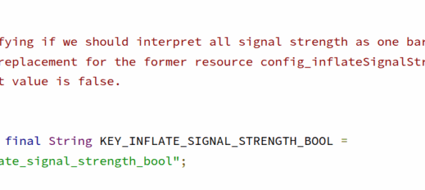
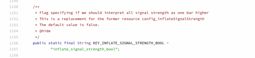
Poking around in Android the other day I found this nugget in Carrier Config manager; a flag (KEY_INFLATE_SIGNAL_STRENGTH_BOOL) to always report the signal strength to the user as one bar higher than it really is.
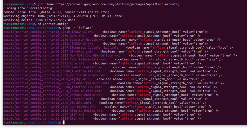
Notably both AT&T and Verizon have this flag enabled on their networks, I’m not sure who was responsible for requesting this to be added to Android, nor could I find it in the git-blame, but we can see it in the CarrierConfig which contains all the network settings for each of these operators.
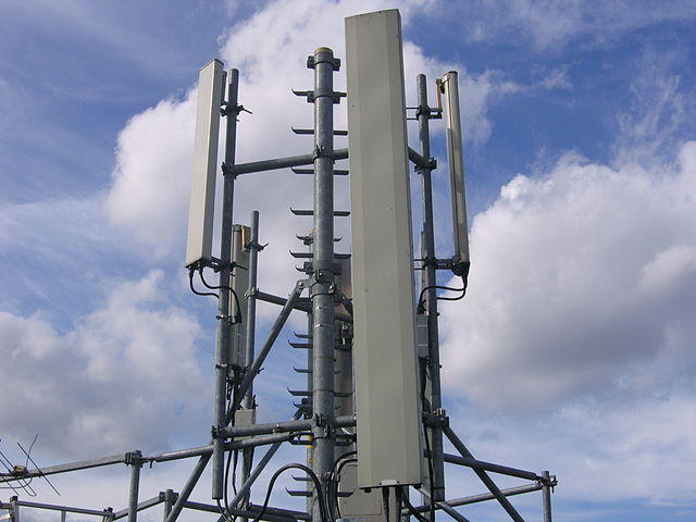
Operators are always claiming to have the biggest coverage or the best network, but stuff like this, along with the fake 5G flags, don’t help build trust, especially considering the magic mobile phone antennas which negate the need for all this deception anyway.
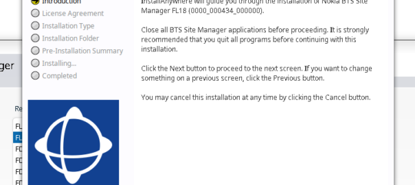
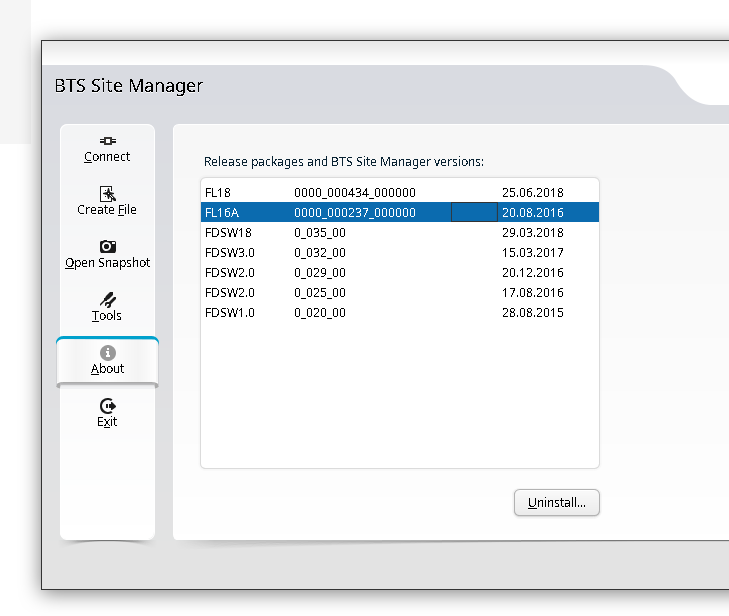
Another post in the “vendors thought Java would last forever but the web would just a fad” series, this one on getting Nokia BTS Site Manager (which is used to administer the pre-Airscale Nokia base stations) running on a modern Linux distro.
For starters we get the installers (you’ll need to get these from Nokia), and install openjdk-8-jre using whichever package manager your distro supports.
Once that’s installed, then extract the installer folder (Like BTS Site Manager FL18_BTSSM_0000_000434_000000-20250323T000206Z-001.zip).
Inside the extracted folder we’ve got a path like:
BTS Site Manager FL18_BTSSM_0000_000434_000000-20250323T000206Z-001/BTS Site Manager FL18_BTSSM_0000_000434_000000/C_Element/SE_UICA/Setup
The Setup folder contains a bunch of binaries.
We make these executable:
chmod +x BTSSiteEM-FL18-0000_000434_000000*
Then run the binary:
sudo ./BTSSiteEM-FL18-0000_000434_000000_x64.bin
By default it installs to /opt/Nokia/Managers/BTS\ Site/BTS\ Site\ Manager
And we’re done. Your OS may or may not have built a link to the app in your “start menu” / launcher.
You can use one BTS manager to manage several different versions of software, but you need the definitions for those software loaded.
If you want to load the Releases for other versions (Like other FLF or FL releases) the simplest way is just to install the BTS site manager for those versions and just use the latest, then you’ll get the table of installed versions in the “About” section that you can administer.
Concrete, steel and labor are some of the biggest costs in building a cell site, and yet all the focus on cost savings for cell sites seems to focus on the RAN, but the actual RAN equipment isn’t all that much when you put it into context.
I think this is mostly because there aren’t folks at MWC promoting concrete each year.
But while I can’t provide any fancy tricks to make towers stronger or need less concrete for foundations, there’s some potential low-hanging fruit in terms of installation of sites that could save time (and therefor cost) during network refreshes.
I don’t think many folks managing the RAN roll-outs for MNOs have actually spent a week with a tower crew rolling this stuff out. It’s hard work but a lot of it could be done more efficiently if those writing the MOPs and deciding on the processes had more experience in the field.
Disclaimer: I’m primarily a core networks person, this is the job done from a comfy chair. This is just some observations from the bits of work I’ve done in the field building RAN.
Standardize Power Connectors
Currently radio units from the biggest RAN vendors (Ericsson, Nokia, Huawei, ZTE & Samsung) each use different DC power connectors.
This means if you’re swapping from one of these vendors to another as part of a refresh, you need new power connectors.
If you’re lucky you’re able to reuse the existing DC power cables on the tower, but that means you’re up on a tower trying to re-terminate a cable which is a fiddly job to do on the ground, and far worse in the air. Or if you’re unlucky you don’t have enough spare distance on the DC cables to do the job, then you’re hauling new DC cables up a tower (and using more cables too).
While Huawei and ZTE have adopted for push connectors with the raw cables behind a little waterproof door.
If we could just settle on one approach (either is fine) this could save hours of install time on each cell site, extrapolate that across thousands of cell sites for each network, and this is a potentially large saving.
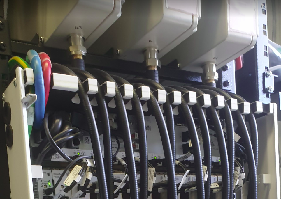
Standardize Fiber Cables
The same goes for waterproofing fibre, Ericsson has a boot kit that gets assembled inline over the connectors, Nokia has this too, as well as a rubber slide over cover boot on pre-term cables.
Again, the cost is fairly minimal, but the time to swap is not. If we could standardize a break out box format on the top of the tower and a LC waterproofing standard, we could save significant time during installs, and as long as you over-provision the breakout (The cost difference between a 6 core fiber vs a 48 core fibre is a few dollars), you can save significant time having to rerun cables.
Yes, we’ve all got horror stories about someone over-bending fiber, and if you reused fibre between hardware refresh cycles, but modern fiber is crazy tough so the chances of damaging the reused fiber is pretty slim, and spare pairs are always a good thing.
Preterm DC Cables
Every cell site install features some poor person squatting on the floor (if they’re savvy they’ve got a camping stool or gardening kneeling mat) with a “gut buster” crimping tool swaging on connectors for the DC lugs.
If we just used the same lugs / connectors for all the DC kit inside the cell sites, we could have premade DC cables in various lengths (like everyone does with Ethernet cables now), rather than making each and every cable off a spool (even if it is a good ab workout).
I dunno, I’m just some Core network person who looks at how long all this takes and wonders if there’s a way it could be done better, am I crazy?
When Dickens wrote of Doctor Manette in the 1859, I doubt his intention was to write about the repeating history of RAN fronthaul standards – but I can’t really say for sure.
Setting the Scene
Our story starts with introducing CPRI (Common Public Radio Interface) interface, having been imprisoned in the Bastille of vendor lock in for the better part of twenty years.
Think of CPRI is less of a hard interoperable standard and more like how the Italian and French languages are both derived from Latin; it doesn’t mean that the two languages are the same, but they’ve got the same root and may share some common words and structures.
In practice this means that taking an Ericsson Radio and plugging it into a Huawei Baseband simply won’t work – With CPRI you must use the same vendor for the Baseband and the Radios.
“Nuts to this” the industry said after being stuck locked between the same radios and baseband for years; we should create a standard so we can mix and match between radio vendors, and even standardize some other stuff that’s been bothering us, so we’ll have a happy world of interoperability.
A world with interoperable fronthaul
With kit created that followed this standard, we’d be able to take components from vendor A, B & C, and fit them together like Lego, saving you some money along the way and giving you’ve got a working solution made of “best of breed” components, where everything is interoperable.
Omnitouch Lego base stations, which also fit together like Lego – Part of the Omnitouch Network Services “swag” from 2024
So the industry created a group to chart a path for a better tomorrow by standardizing these interfaces.
The group had many industry heavyweights like Nokia, NEC, LG, ZTE and Samsung joining.
The key benefits espoused on their website:
An open market will substantially reduce the development effort and costs that have been traditionally associated with creating new base station product ranges. The availability of off-the-shelf base station modules will enable manufacturers to focus their development efforts on creating further added value within the base station, encouraging greater innovation and more cost-effective products. Furthermore, as product development cycles will be reduced, new base station functions will become available on the market more quickly.
Mission statement of the group
In addition to being able to mix and match radios and basebands from different vendors, the group defined standards for centralized baseband, and interoperable standards, to allow a multi-vendor ecosystem to flourish.
And here’s the plot twist – The text above, was not written about OpenRAN, and it was not written about the benefits of eCPRI.
It was written about Open Base Station Architecture Initiative (OBSAI) and it was written 22 years ago.
*record screech sound*
Standards War you’ve never heard of: OBSAI vs CPRI
When OBSAI was defined it was not without competition; there was another competing fronthaul standard; that’s right, the mustache twirling lowlife from earlier in the story – CPRI.
Supported by Huawei, Nortel, NEC & Ericsson (among others), CPRI took a “gentle parenting” approach to the standards world, in contrast to OBSAI. Instead of telling all the vendors to agree on an interoperable front haul standard, CPRI just encouraged everyone to implement what their heart told them and what felt right to them.
As it happened, the industry favored the CPRI approach.
If a vendor wanted to add a new “word” in their CPRI “language” to add a new feature, they just went ahead and added it – It didn’t require anyone else to agree with them or changes to a common standard used by the industry, vendors could talk to the kit they made how they wanted.
CPRI has been the defacto non-standard used by all the big kit vendors for the past ~10 years.
The Death of OBSAI & the Birth of OpenRAN’s eCPRI
Why haven’t you heard of OBSAI? Why didn’t the OBSAI standard just serve as the basis for eCPRI – After all the last OBSAI release was less than 5 years before TIP started working on eCPRI publicly.
Is no more. It has ceased to be.
Did a schism over “uplink performance improvement” options lead to “irreconcilable differences” between parties leading to the breakup of the OBSAI group?
Nope.
Customers (MNOs) didn’t buy OBSAI based equipment in measurably larger quantities than CPRI kit. That’s it.
This meant the vendors invested less in paying teams to further develop the standards, the OBSAI group met less frequently, and in the end, member vendors didn’t bother adding support for OBSAI to new equipment and just used the easier and more flexible CPRI option instead.
At some point someone just stopped paying for the domain renewal and that was it, OBSAI was no more.
This is how the standards body ends, not with a bang, but with a whimper.
T.S. Elliot’s writings on the death of obsai
Those who do not learn from history…
The goals of the OBSAI Group and OpenRAN working groups are almost identical, so what lessons did Marconi, Motorola and Alcatel learn as members of OBSAI that other vendors could learn about OpenRAN strategy?
There are no mentions of OBSAI in any of the information published by OpenRAN advocates, and I’m wondering if folks aren’t aware that history tends to repeat and are ignorant to what came before it, or they’re just not learning lessons from the past?
So what can the OpenRAN industry learn from OBSAI?
Being a nerd, I started detailing the technical challenges, but that’s all window dressing; The biggest hurdle facing CPRI vs eCPRI are the same challenges OBSAI vs CPRI faced a decade prior:
To be relevant, OpenRAN kit has to be demonstrably better than what we have today AND provide a tangible cost saving.
OBSAI failed at achieving this, and so failed to meet it’s other more noble goals.
[At the time of writing this at least] I’d contend that neither of those two criteria have been met by OpenRAN.
What does the future hold for OpenRAN?
Looking into the crystal ball, will OpenRAN and eCPRI go the way of OBSAI, or will someone keep the OpenRAN dream alive?
Today, we’re still seeing the MNOs continue to provide tokenistic investment in OpenRAN. But being a cynic, I’d say the MNOs are feigning interest in OpenRAN products because it’s advantageous for them to do so.
The threat of OpenRAN has proven to be a great stick to beat the traditional vendors with to force them to lower their prices.
Think about the $14 billion USD Ericsson deal with AT&T, if chucking a few million at OpenRAN pilots / trials lead to AT&T getting even a 0.1% reduction in what they’re paying Ericsson, then the numbers would have worked out well in AT&Ts favor.
From the MNOs perspective, the cost to throw the odd pilot or trial to a hungry OpenRAN vendor to keep them on the hook is negligible, but the threat of OpenRAN provides leverage and bargaining power every time it’s contract renewal time with the big RAN vendors.
Already we’ve seen all the traditional RAN vendors move to neutralize this threat by introducing “OpenRAN compatible” equipment and talking up their commitment to openness.
This move by the RAN vendors takes this sting out of the OpenRAN threat, and means MNOs won’t have much reason to continue supporting OpenRAN.
This leaves the remaining OpenRAN vendors like Miss Havisham, forever waiting in their proverbial wedding dresses, having being left at the altar.
Okay, I’m mixing my Dickens’ references here, but it was too good not to.
Appendix
I’ve been enjoying writing more analysis than just technical content, let me know if this is something you’re interested in seeing more of.
I’ve been involved in two big OpenRAN integration projects, both of which went poorly and probably tainted my perspective. Enough time has passed to probably write up how it all went with the vendor names removed, but that’s a post for another time!
Technology is constantly evolving, new research papers are published every day.
But recently I was shocked to discover I’d missed a critical development in communications, that upended Shannon’s “A mathematical theory of communication”.
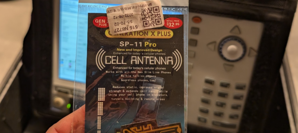
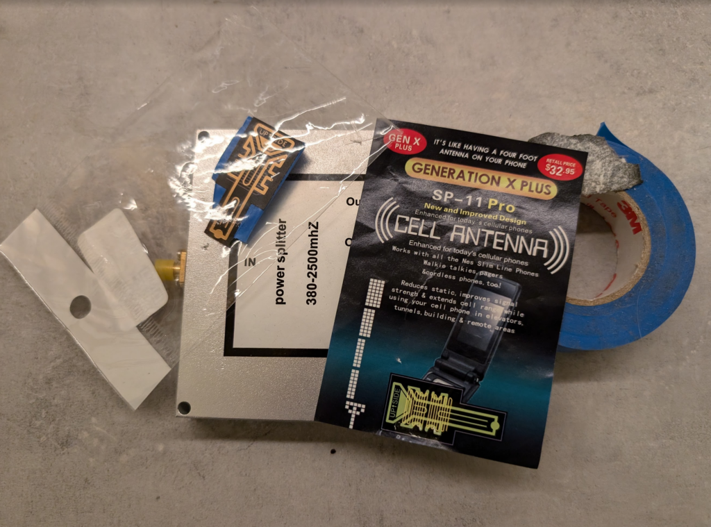
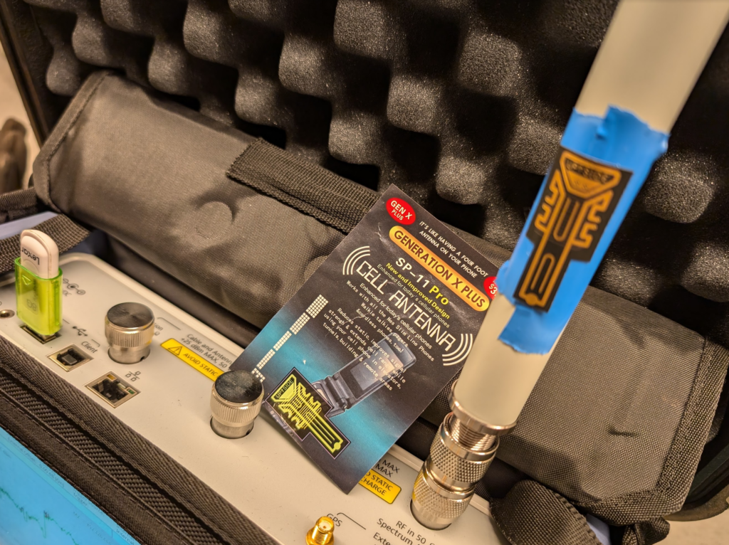
I’m talking of course, about the GENERATION X PLUS SP-11 PRO CELL ANTENNA.
I’ve been doing telecom work for a long time, while I mostly write here about Core & IMS, I am a licenced rigger, I’ve bolted a few things to towers and built my fair share of mobile coverage over the years, which is why I found this development so astounding.
With this, existing antennas can be extended, mobile phone antennas, walkie talkies and cordless phones can all benefit from the improvement of this small adhesive sticker, which is “Like having a four foot antenna on your phone”.
So for the bargain price of $32.95 (Or $2 on AliExpress) I secured myself this amazing technology and couldn’t wait to quantify it’s performance.
Think of the applications – We could put these stickers on 6 ft panel antennas and they’d become 10ft panels. This would have a huge effect on new site builds, minimize wind loading, less need for tower strengthening, more room for collocation on the towers due to smaller equipment footprint.
Luckily I have access to some fancy test equipment to really understand exactly how revolutionary this is.
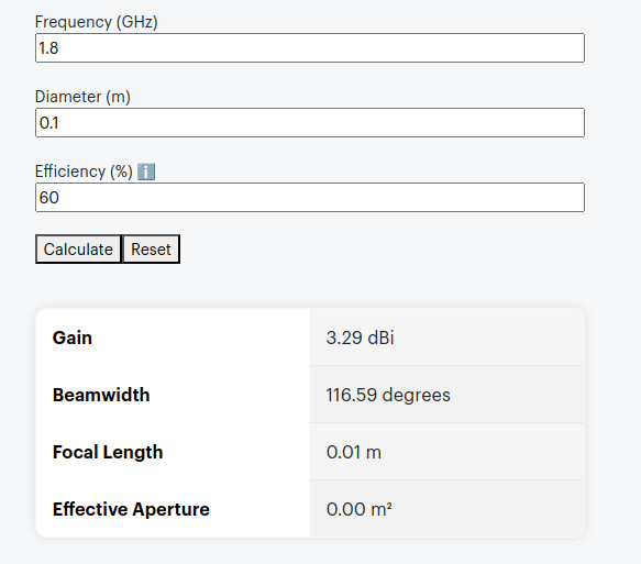
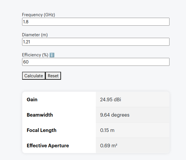
The packaging says it’s like having a 4 foot antenna on your phone, let’s do some very simple calculations, let’s assume the antenna in the phone is currently 10cm, and that with this it will improve to be 121cm (four feet).
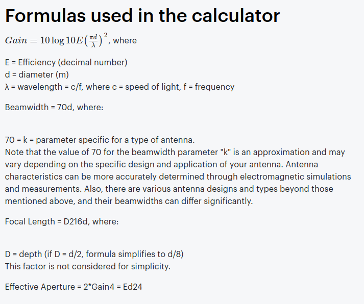
Projected Gain (Post Sticker)Formulas Used
According to some basic projections we should see ~21dB gain by adding the sticker, that’s a 146x increase in performance!
Man am I excited to see this in action.
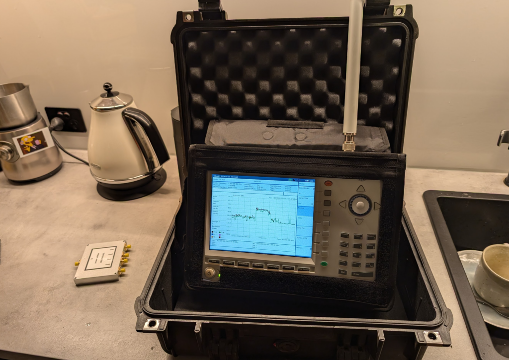
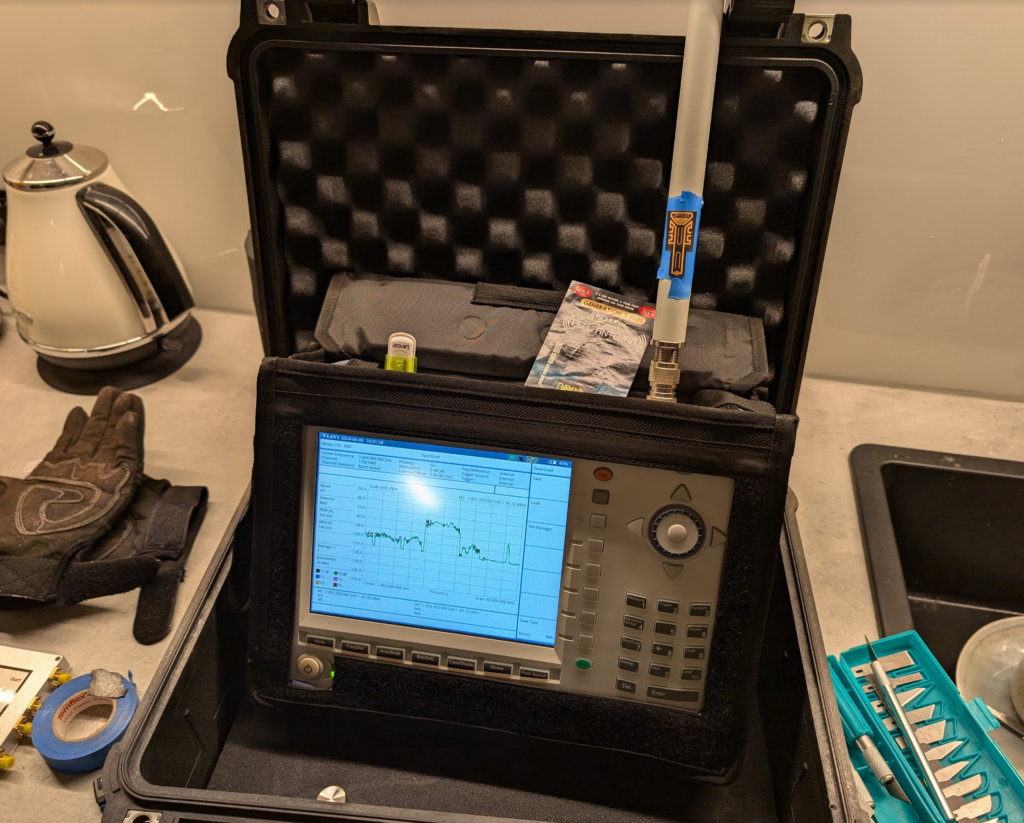
Fortunately I have access to some fun cellular test equipment, including the Viavi CellAdvisor and an environmentally controlled lab my kitchen bench.
I put up a 1800Mhz (band 3) LTE carrier in my office in the other room as a reference and placed the test equipment into the test jig (between the sink and the kettle).
We then took baseline readings from the omni shown in the pictures, to get a reading on the power levels before adding the sticker.
We are reading exactly -80dBm without the sticker in place, so we expertly put some masking tape on the omni (so we could peel it off) and applied the sticker antenna to the tape on the omni antenna.
At -80dBm before, by adding the 21dB of gain, we should be put just under -60dBm, these Viavi units are solid, but I was fearful of potentially overloading the receive end from the gain, after a long discussion we agreed at these levels it was unlikely to blow the unit, so no in-line attenuation was used.
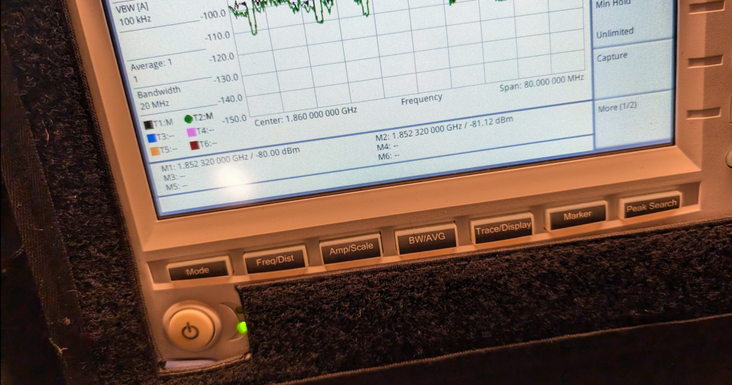
Okay, </sarcasm> I was genuinely a little surprised by what we found; there was some gain, as shown in the screenshot below.
Marker 1 was our reference without the sticker, while reference 2 was our marker with the sticker, that’s a 1.12dB gain with the sticker in place. In linear terms that’s a ~30% increase in signal strength.
Screenshot
So does this magic sticker work? Well, kinda, in as much that holding onto the Omni changes the characteristics, as would wrapping a few turns of wire around it, putting it in the kettle or wrapping it in aluminum foil. Anything you do to an antenna to change it is going to cause minor changes in characteristic behavior, and generally if you’re getting better at one frequency, you get worse at another, so the small gain on band 3 may also lead to a small loss on band 1, or something similar.
So what to make of all this? Maybe this difference is an artifact from moving the unit to make a cup of tea, the tape we applied or just a jump in the LTE carrier, or maybe the performance of this sticker is amazing after all…
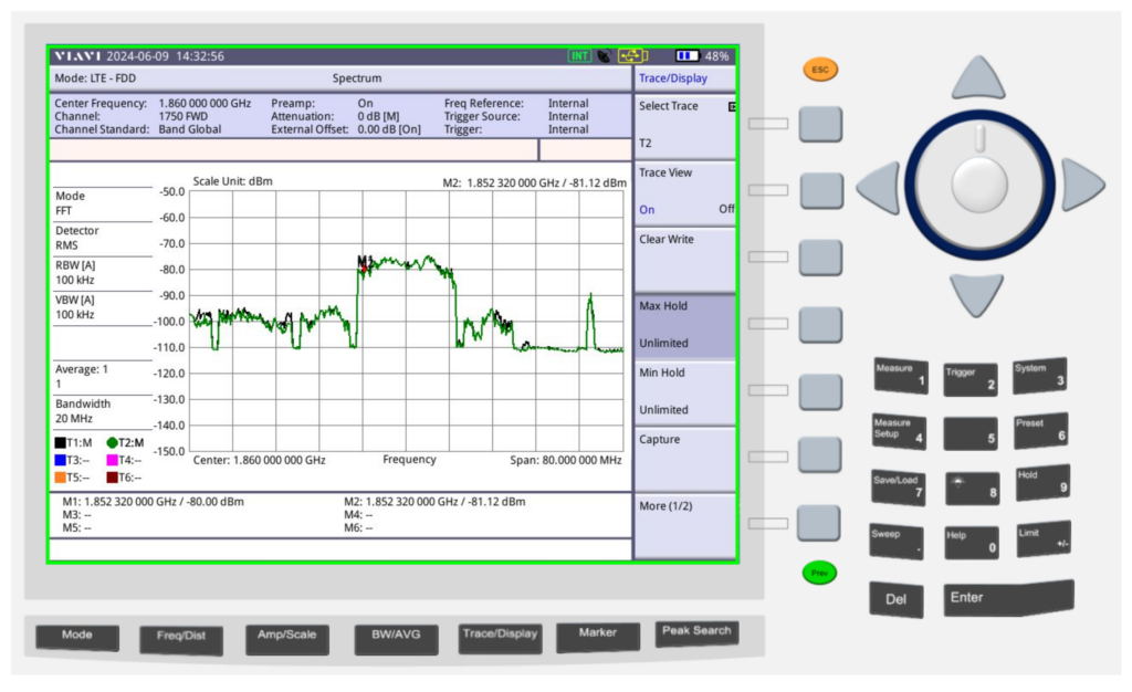
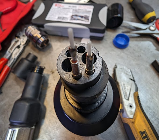
I came across these the other day, they’re DC & Fibre in the same connector body.
Rather than breaking out to a fibre and an Anderson connector, you’ve got both in one connector, with provision for an extra fibre pair too, then on the other end this splits into the RRU power connector, used by Ericsson and Nokia, and a LC connector for the fibre into the RRU.
I pulled it all apart this to see how it fitted together, it looks like they’re factory pre-term cables, rather than being spliced to length, which I guess makes sense. Cool design!
Up close view of the connectorDC breaks out when you pull it apartAnd the fibres are held in with springs to the top half of the connector bodyAnd the breakout to LC and RRU DC connectors
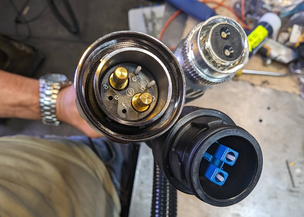
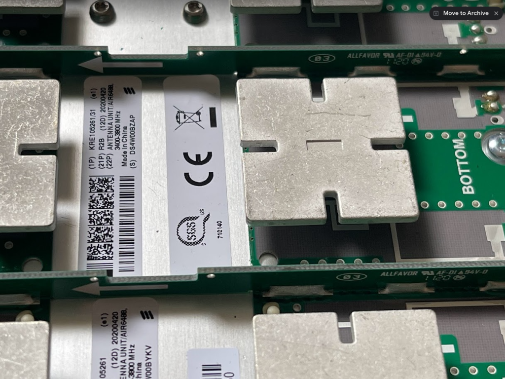
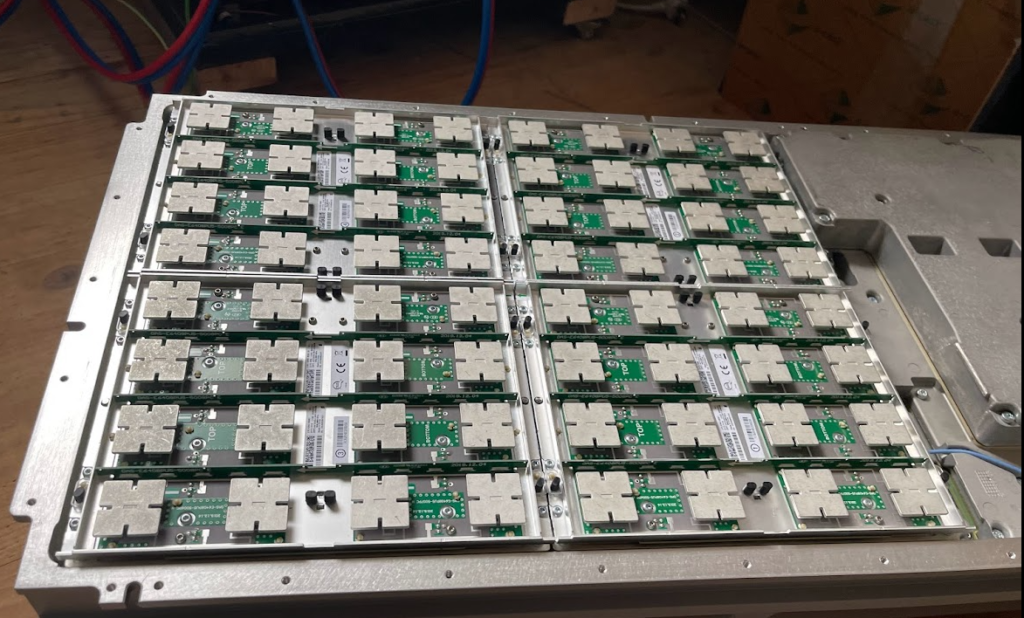
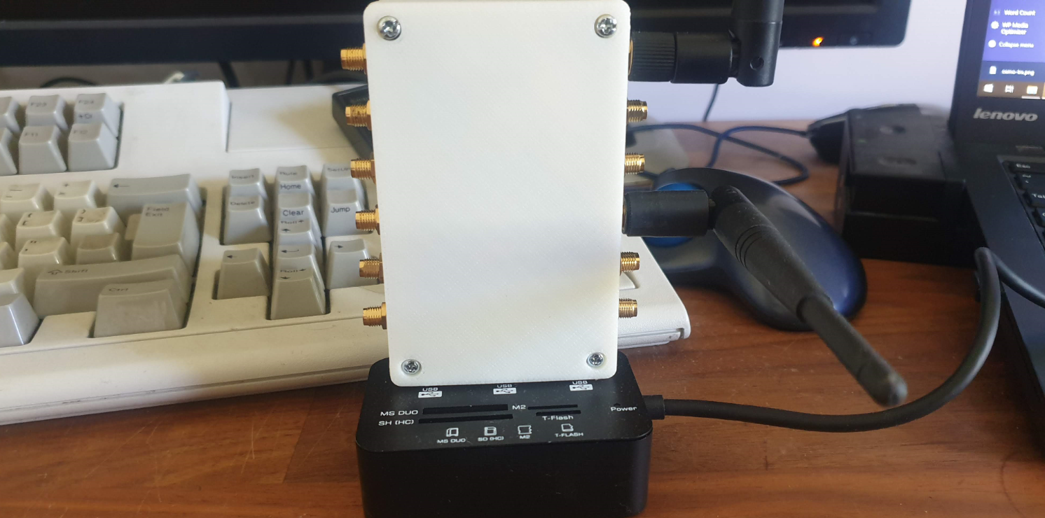
For the past few months I’ve had a Band 78 NR active antenna unit sitting next to my desk.
It’s a very cool bit of kit that doesn’t get enough love, but I thought I’d pop open the radome and take a peek inside.
Individual antenna elements
What I found very interesting is that it’s not all antennas in there!
… 29, 30, 31, 32. Yup. Checks out.
There are the expected number of antennas (I mean if I opened it up and found 31 antennas I’d have been surprised) but they don’t take up the whole volume of the unit, only about half,
AAU with Radome reinstalled
Well, after that strip show, back to sitting in my office until I need to test something 5G SA again…
How do humans talk to base stations? For Huawei at least the answer to this is through MML – Man-Machine-Language,
It’s command-response based, which is a throwback to my Nortel days (DMS100 anyone?),
So we’re not configuring everything through a series of parameters broken up into sections with config, it’s more statements to the BTS along the lines of “I want you to show me this”, or “Please add that” or “Remove this bit”,
The instruction starts of with an operation word, telling the BTS what we want to do, there’s a lot of them, but some common examples are; DSP (Display), LST (List), SET (Set), MOD (Modify) and ADD (Add).
After the operation word we’ve got the command word, to tell the BTS on what part we want to execute this command,
A nice simple example would be to list the software version that’s running on the BTS. For this we’d run
LST SOFTWARE:;
And press F9 to execute, which will return a list of software on the BTS and show it in the terminal.
Note at the end the :; – the : (colon) denotes the end of a command word, and after it comes the paratmeters for the command, and then the command ends with the ; (semi-colon). We’ll need to put this after every command.
Let’s look at one more example, and then we’ll roll up our sleves and get started.
Note: I’m trying out GIFs to share screen recordings instead of screenshots. Please let me know if you’re having issues with them.
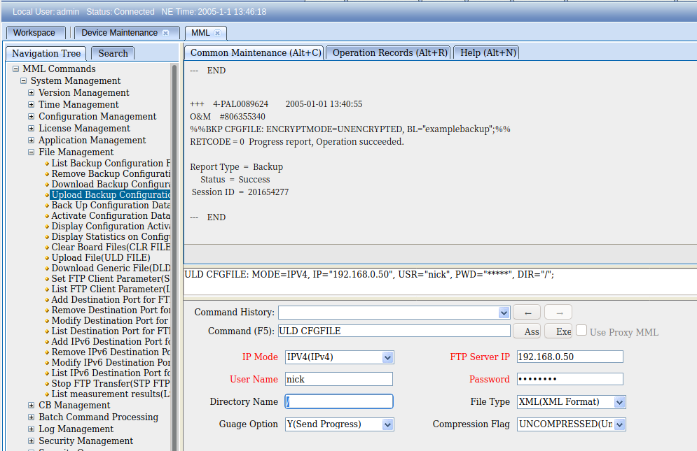
So once you’ve logged into WebLMT, selecting MML is where we’ll do all our config, let’s log in and list the running applications.
So far we’ve only got some fairly basic data, listing and displaying values, so let’s try something a bit more complex, taking a backup of the config, in encrypted mode, with the backup label “blogexamplebackup”,
If you’ve made it this far there’s a good chance you’re thinking there’s no way you can remember all these commands and parameters – But I’ve got some good news, we don’t really need to remember anything, there’s a form for this!
And if we want to upload the backup file to an FTP server, we can do this as well, in the navigation tree we find Upload Backup Configuration, fill in the fields and click the Exec button to execute the command, or press F9.
These forms, combined with a healthy dose of the search tab, allow us to view and configure our BTS.
I’ve still got a lot to learn about getting end-to-end configuration in place, but this seems like a good place to start,
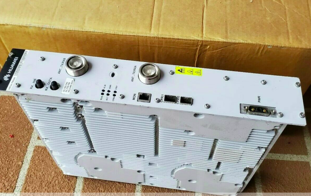
Meta: The Australian government made up it’s mind some time ago that Huawei would be blacklisted from providing equipment for 5G networks. Several other countries have adopted the same policy in regards, and as such, deployed Huawei tech is being replaced, and some of it filters down to online auction sites…
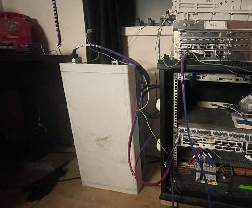
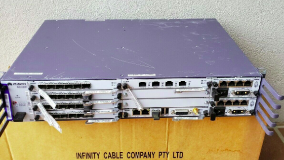
So I kind of purchased an item described as “Huawei BBU3900” with a handful of unknown cards and 2 LRFU units, for just over $100.
My current lab setup is a single commercial picocell and a draw of SDR hardware that works with mixed results, so the idea of having a commercial macro cell to play with seemed like a great idea, I put lowball offer in and the seller accepted.
Now would be a good time to point out I don’t know much about RAN and it’s been a long time since I’ve been working on power systems, so this is shaping up to be a fun project.
Photo from the listing
Photo from the listing
I did a Huawei RAN course years ago and remembered the rough ingredients required for LTE:
You needed either RRUs (Remote Radio Units) or RFUs (Radio Frequency Units) to handle the RF side of things. RRUs are designed for outdoor use (such as mounting on the tower) and RFUs are designed for indoor use, like mounting in a cabinet. I’ve ended up with two LRFUe units, which I can join together for 2x MIMO, operate on Band 28 and can put out a whopping 80W of transmit power, yes I’m going to need some big attenuators…
You need a Baseband Processor card to tell the Radio units what do do. The card connects the CPRIs (Typically optic fiber links) between the radio units and the baseband. The chassis I purchased came with a stack of WBBP (For WCDMA) cards and a single LBBP card for LTE. The LBBP card has 6 SFP ports for the CPRI interfaces, which is more than enough for my little lab. (You can also daisy-chain CPRIs so I’m not even limited to 6 Radio Units.)
You need a backplane and a place for the cards to live – this is the BBU3900 chassis. It’s got basic switching to allow communication between cards, a chassis to distribute power and cooling. (Unlike the Ericson units there is actually a backplane for communications in the Huawei chassis – the Ericsson RBS series has is just power and cooling in the chassis)
Optional – Dedicated transmission card, I’ve ended up with a Universal Transmission Processor (UTRP9) with 2x Gig Ethernet and 2x Fast Ethernet ports for transmission. This will only work for GSM and UMTS though, not LTE, so not much use for me.
You need something to handle main processing (LTE / Universal Main Processing and Transmission Unit (LMPT / UMPT)). Unfortunately the unit I’ve ended up with only came with a WMPT (For WCDMA), so back online to find either an LMPT (LTE) or UMPT (Universal (2G/3G/4G))…
You need a Universal Power and Environment Module (UPEU) to power up the chassis and handle external IO for things like temperature alarms, door sensors and fire detectors. This chassis has two for redundancy / extra IO & extra power capacity.
So in order to get this running I still need quite a few components:
Attenuators – I’ll be able to turn the power down, sure, but not to the levels required to be legal.
Antennas – These are FDD units, so I’ll need two antennas for each RFU, on Band 28
Feeder Cables – To connect the antennas
SMF cables and SFPs – I’ve got a pile in my toolbox, but I’ll need to work out what’s supported by these units
A big -48vDC rectifier (I got the BBU3900 unit powered up with an existing supply I had, but I’m going to need something bigger for the power hungry RFUs)
DC Distribution Unit – Something to split the DC between the RFUs and the BBU, and protect against overload / short
USB-Network adapter – For OAM access to the unit – Found these cheaply online and got one on the way
The LTE Main Processing & Transmission (LMPT) card – Ordered a second hand one from another seller
I powered up the BTA3900 and sniffed the traffic, and can see it trying to reach an RNC.
Unfortunately with no open source RNC options I won’t be posting much on the topic of UMTS or getting the UMTS/WCDMA side of things on the air anytime soon…
So that’s the start of the adventure.
I don’t know if I’ll get this all working, but I’m learning a lot in the process, and that’s all that really matters…
SS7 was first introduced in the 1970s and initially was designed for large scale setting up and tearing down of calls, but due to it’s layered architecture and prominence in the industry has been used for signalling between some CS network elements in Mobile Networks, including transporting messages between the MSC and any BSCs or RNCs it’s serving.
This is going to be fairly brief and Osmocom specific, keep in mind SS7 is a giant topic so there’s a huge amount we won’t cover.
Point Codes – SS7 Addressing & Routing
Historically SS7 networks were carried over TDM links of various types, and not over TCP/IP.
A point code is a unique address associated with each network element for addressing messages between network elements, it’s function is similar to that of an IP Address you’d use in IP networks.
When STP messaging is sent it includes a Source Point Code (SPC) and Destination Point Code (DPC).
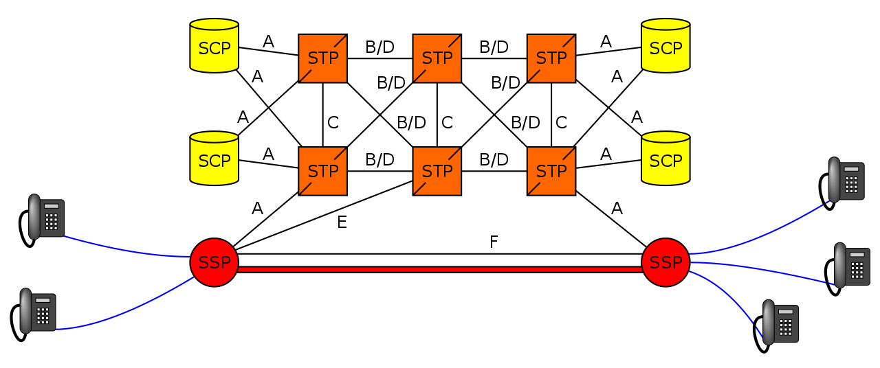
The Signalling Transfer Point
Instead of a one-to-one connection between each SS7 device and every other SS7 device, a network element called a Signaling Transfer Point (STP) is used, which acts somewhat like a router.
The STP has an internal routing table made up of the Point Codes it has connections to and some logic to know how to get to each of them.
When it receives an SS7 message, the STP looks at the Destination point code, and finds if it has a path to that point code. If it does, it forwards the SS7 message on to the destination.
Like a router, an STP doesn’t really concern itself with the upper layer protocols and what they contain – As point codes are set in the MTP3 layer that’s the only layer the STP looks at and the upper layers aren’t really “any of its business”.
Sigtran & SS7 Over IP
As the world moved towards IP enabled everything, TDM based Sigtran Networks became increasingly expensive to maintain and operate, so a IETF taskforce called SIGTRAN was created to look at moving SS7 traffic to IP.
The first layer of SS7 were dropped it primarily concerned the physical side of the network, and in the Osmocom implementation the MTP3 layer and up were put into SCTP packets and carried on the network.
Notice I said SCTP and not TCP or UDP? I’ve touched upon SCTP on this blog before, it’s as if you took the best bits of TCP without the issues like head of line blocking and added multi-homing of connections.
To establish an SS7 connection over IP the MTP3 message an SCTP socket is established from the device to the STP, and then an ASP Maintenance message is sent, followed by a Registration Request containing it’s point code, and presto, we have a connection.
The Osmo STP
The Osmocom STP acts in a very trusting manner by default,
When a device wants to connect to the STP it does so via a REG_REQ (Registration Request) containing it’s Point Code. The STP accepts the connection with a REG_RSP (Registration Response).
For as long as that connection stays up any SS7 messages destined to that point code of the device that just registered, the STP will now how to get it there.
Assuming you’ve already installed the OsmoSTP you can access it on 4239:
root@gsm-bts:/etc/osmocom# telnet localhost 4239
Trying 127.0.0.1…
Connected to localhost.
Welcome to the OsmoSTP VTY interface
OsmoSTP>
After running enable we can check the current routing table:
OsmoSTP# show cs7 instance 0 sccp users
SS7 instance 0 has no SCCP
OsmoSTP# show cs7 instance 0 ro
OsmoSTP# show cs7 instance 0 route
Routing table = system
C=Cong Q=QoS P=Prio
Destination C Q P Linkset Name Linkset Non-adj Route

0.23.1/14 0 as-rkm-1 ? ? ?
0.23.3/14 0 as-rkm-2 ? ? ?

OsmoSTP# show cs7 instance 0 as all
Routing Routing Key Cic Cic Traffic
AS Name State Context Dpc Si Opc Ssn Min Max Mode

as-rkm-1 AS_ACTIVE 1 0.23.1 override
as-rkm-2 AS_ACTIVE 2 0.23.3 override

OsmoSTP# show cs7 instance 0 asp
Effect Primary
ASP Name AS Name State Type Remote IP Addr:Rmt Port SCTP
------------ ------------ ------------- ---- ----------------------- ----------
asp-dyn-0 ? ASP_ACTIVE m3ua 127.0.0.1:52192
asp-dyn-1 ? ASP_ACTIVE m3ua 127.0.0.1:33570
Packet Capture
Below is a packet capture showing a connection from an MSC to the STP.
So SDR is all well and good, but a late night eBay purchase landed me two ipaccess NanoBTS units second hand from the US.
The hefty metal units are designed as GSM access points / picocells for indoor use, with a stable Uu / radio interface and speaking Abis over IP, it integrates nicely with Osmocom’s stack and was used by the Osmocom team as a bit of a development platform in the past.
Finding the Current IP
Because these units are second hand, first step was finding the current IP.
I ran a packet capture on the interface the units were plugged into until I saw some traffic showing their current IP.
Once you’re in the correct subnet you can use the abisip-find tool to find any units:
abisip-find
Mine showed up on a 10.97.99.15 IP, so I put my machine on the 10.97.99.x/24 subnet so I could reach them.
Changing IP Details
Once I had the current IP details it was time to change the IP details, Unit ID and OML / AbisIP IP address.
My unit came on 10.97.99.15, but I wanted it on 10.0.1.204/24 and pointed to my BSC at 10.0.1.201, so I set that using the command,
So we’ve got a functional network, but let’s dive deeper into what we can do to connect it with other networks and how things work in “the real world”.
Media Handling – OsmoMGW
The Audio/Voice (media stream) data on a call between subscribers does not go directly between the subscribers and instead needs to be proxed relayed. The reason for this is because there’s no direct link from one BTS to another BTS (even if they are served by the same BSC) and as our subscribers can move from cell to cell while on a call – which may mean moving from one BSC to another depending on where they’re heading – we need to have a single point for the audio to remain.
To handle this a Media Gateway is used, a single point for call audio to be “anchored” – meaning regardless of which BTS/BSC is serving the subscribers on either end of the call, the media will be sent by both parties to a single destination (The Media Gateway), and that destination will send the audio to the other party.
The Media gateway relays / proxies the Media Stream – the RTP packets containing the call audio. OsmoMSC provides the SDP payload containing the codecs and RTP details for the session via MGCP (Media Gateway Control Protocol) to the OsmoMGW which relays the audio.
In terms of running osmo-mgw we installed it earlier,
The only parameter you really need to change is the rtp bind-ip,
On the MGW you can also limit and restrict the codecs supported and also allow or disallow transcoding.
MNCC-SAP & Call Routing
In it’s default mode, the OsmoMSC will look at the destination a call is being sent to, and if the destination is a subscriber on the network (in it’s VLR), will route the call to that subscriber
This on-net only mode is great but it puts our network on an island – cut off from the outside world.
Calls between MSCs, to the PSTN and users everywhere else are not possible in this scenario.
3GPP defined “MNCC-SAP” (Mobile Network Call Control – Service Access Point) a protocol for handling calls to/from destinations outside of the local MSC.
When in MNCC-SAP mode all calls (even on-net calls between subscribers on the same MSC) are routed to the external MNCC-SAP, and left up to it to determine how to route the call.
Configuring Osmo-MSC to talk MNCC
As we just covered by default Osmo-MSC only switches calls internally between subscribers, so we’ll need to turn off this behaviour and isntead reconfigure it to talk MNCC-SAP.
To do this we’ll telnet / VTY into Osmo-MSC;
root@gsm-bts:/etc/osmocom# telnet localhost 4254
Welcome to the OsmoMSC VTY interface
OsmoMSC - Osmocom Circuit-Switched Core Network implementation
OsmoMSC> enable
OsmoMSC# configure terminal
OsmoMSC(config)# msc
OsmoMSC(config-msc)# mncc external /tmp/msc_mncc
OsmoMSC(config-msc)# end
OsmoMSC# cop run st
Configuration saved to /etc/osmocom/osmo-msc.cfg
After making this change we have to restart OsmoMSC;
systemctl restart osmo-msc
Now OsmoMSC will not switch calls locally, but instead when a mobile originated call comes to the MSC, it will signal to the external MNCC via the file sock at /tmp/msc_mncc,
MNCC-SAP sounds great but platform X only speaks SIP
Enter the Osmo-SIP-Connector, which takes the MNCC-SAP messages and converts them to SIP.
From here you can tie the call control functions of the MNC into any SIP software such as Kamailio, FreeSwitch, Asterisk, etc, to handle call routing, number translation, application services like voicemail and conferencing, etc, etc.
On my to-do list is to make a call between one subscriber on GSM and one on VoLTE, I’ll cover that in a subsequent post.
So anywho, let’s get Osmo-SIP-Connector setup, I’m running it on the same box as the MSC on 10.0.1.201, My softphone client is running on 10.0.1.252
root@gsm-bts:/etc/osmocom# apt-get install osmo-sip-connector
root@gsm-bts:/etc/osmocom# telnet localhost 4256
Welcome to the OsmoSIPcon VTY interface
OsmoSIPcon> enable
OsmoSIPcon# configure t
OsmoSIPcon(config)# mncc
OsmoSIPcon(config-mncc)# socket-path /tmp/msc_mncc
OsmoSIPcon(config-mncc)# exit
OsmoSIPcon(config)# sip
OsmoSIPcon(config-sip)# local 10.0.1.201 5060
OsmoSIPcon(config-sip)# remote 10.0.1.252 5060
OsmoSIPcon(config-sip)# end
OsmoSIPcon# cop run st
Configuration saved to /etc/osmocom/osmo-sip-connector.cfg
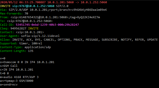
Now any Mobile Originated calls will result in a SIP INVITE being sent to 10.0.1.252 port 5060 (using UDP).
Any SIP INVITES where the request URI is a valid MSISDN @ 10.0.1.201 from 10.0.1.252 will be routed to the correct subscriber for that MSISDN.
A small note – The GSM codec is (unsurprisingly) used as the codec for GSM calls by default.
Some handsets support different codecs, but many off-the-shelf IP phones don’t include GSM support, so you may find you’re required to transcode between codecs if there is no support for the other codecs.
So now we’re able to define our call routing logic in something that speaks SIP and connect calls between multiple MSCs, VoLTE / IMS networks and fixed networks, all based on what we do with the SIP.
Local Call, Local Switch
If two subscribers on the same BSC call each other, the RTP / call audio will route to the MGW where it’s anchored.
This makes sense from a mobility standpoint, but adds load to the MGW and relies on a quality A interface connection, which may be an issue depending on what backhaul options you have.
Local Call, Local Switch is a 3GPP spec to allow the RTP / call audio to act as the RTP proxy instead of the MGW.
So now we’ve covered the basics of what’s involved let’s get some traffic on our network.
For starters we’ll need to start each of our network elements and bring up whichever BTS hardware we’re using.
In order for our calls to have audio, we’ll need to set a parameter on the Media Gateway. We’ll cover the Media Gateway in more detail down the line, but there’s one value in the MGW we’ll need to set in order to have calls working, and that’s the rtp bind-ip value. You can either set it in the config file or via VTY/Telnet on port 4243.
We’ve talked about using systemctl to start all the services, but there’s a script in the /etc/osmocom directory called osmocom-all.sh which starts all the network elements for us.
Once you’ve got all the services started I’d suggest hopping onto the OsmoBSC and enabling all the logging you can, then connecting / starting your BTS.
You should see the Abis over IP connection & OML link come up as the BTS connects to the BSC.
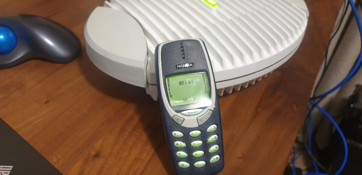
And then, hold your breath, power up a phone and search for networks.
All going well you’ll see OsmoMSC in the network search, select it and you should see log data flying by as the phone (“terminal”) connects to the network.
Assuming you configured the IMSI of the SIM on the HLR you should be connected to the network and showing bars on the phone.
You can check your phone number (MSISDN) by dialling the USSD code *#100#
But it’s not a network with just one phone connected, connect a second phone, check it’s phone number the same way and call from one to the other.
SMS should also just work.
And there you have it, a functional GSM network!
But this isn’t the end for us, it’s really just the beginning.
There’s still so much more to learn and work on – Over the next few weeks / months we’ll add packet data to the network with GPRS or EDGE, connect into external call routing and SMS routing interfaces, use Circuit Switched Fallback to provide voice service to users on LTE networks and roam between them.
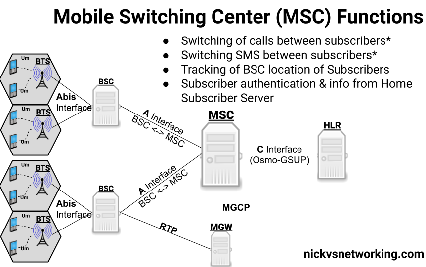
We’re nearing the end of our “setup” story – So far we’ve covered the access network (BTS & BSC) and our subscriber database (The HLR) so now let’s talk about one of the key “Core” elements of the network – the Mobile Switching Center (MSC).
The MSC’s name kind of says it all, it’s a switching center for mobiles.
The MSC handles switching of voice calls and SMS/text messages between local & remote subscribers and networks.
Switching Function
Because GSM was designed to be voice centric (Keep in mind the first GSM network went live in 1991) the MSC’s primary function is switching phone calls between subscribers.* For this the MSC has to keep track of which subscribers it’s currently serving, their capabilities and how to reach them -which BSC they’re being served by and therefore which BTS they’re being served by.
The OsmoMSC also features a minimalistic SMSC (Short Message Service Server) for routing SMS traffic between subscribers on the network. This basic SMSC acts in a store-and-forward fashion. Production networks would typically use an external SMSC for handling SMS, OsmoMSC has the SMSC functionality built in by default, but the interfaces are there if you wanted to use an external SMSC.
Any calls/texts to subscribers/destinations outside the MSC (for example a call to a mobile subscribers on a different carrier or on the PSTN) are typically routed to another MSC known as the Gateway MSC. The GMSC handles the interconnection with other networks. We’ll touch upon this later with the SIP connector, but for now we’ll focus just on on-net calls between subscribers.
It’s worth noting that the MSC does not sit in the media stream, it just sets up and tears down the calls, we’ll cover more on the nitty-gritty of calling in GSM soon.
Visitor Location Register Function
The MSC also acts as the interface to the HLR for AAA, as we covered in our last post, the HLR provides the authentication role and also provides the subscriber data to the MSC. Subscriber data is copied from the HLR to the internal HLR cache on the MSC known as the Visitor Location Register (VLR) after a subscriber attaches.
Authentication, Ciphering and EIR Queries
In the last post we talked about the role of the HLR in terms of Authentication on the network, the authentication vectors but the policies that enforce this are set on the MSC.
The MSC queries the admission control info from the HLR, but it’s the MSC that’s responsible for enforcing these rules.
Core Network Identity
The MCC (Mobile Country Code) and MNC (Mobile Network Code) of the network (Together the MCC + MNC are referred to as the PLMN ID), along with the network name, are configured on the MSC.
While this may seem like a rather small detail, the PLMN ID is analogous to the SSID of a WiFi network – it’s what identifies your network out of all the others on the air, and the network name shows up on your phone when you’re connected showing your network name.
Setup & Connections
The BSC we setup earlier communicates with the MSC via SS7 Point Codes. We’ll go into how point codes route requests in a later post, but so long as you’re running Osmo-BSC, Osmo-MGW, Omso-MSC and Osmo-HLR on the same machine you won’t need to link them to each other like we had to do with adding our BTS to the BSC.
Instead we’ll just need to start everything required:
The GSUP connection between the MSC and the HLR will be established at startup, but BSCs will only establish a connection to the MSC when they need something from the MSC.
Once we’ve got everything started we can Telnet into the MSC to confirm it’s running and check it’s status:
root@gsm # telnet localhost 4254
Assuming you can connect that’s another network element online. – We’ll leave the default the Point Codes in place so the BSC will be able to connect to the MSC, but keep in mind that the BSC will only establish a connection when it needs something from the MSC.
Follow Up
There’s a few topics we skipped over in this topic, stuff like SS7/SIGTRAN, how real world GSM calls route using MNCC-SAP, the Media Gateway and anchoring media streams and what an SMSC does.
I’ll do posts covering each of these topics in more depth.
The Home Location Register serves the AAA functions in a GSM / UMTS (2G/3G) network as well as locating which Mobile Switching Center (MSC) a subscriber is being served by.
One obvious need is to authenticate our subscribers so the network can verify their identity,
The IMSI (International Mobile Subscriber Identity) is used to identifier the user from all the other mobile subscribers worldwide. The IMSI is exposed to the user, but transmitting the IMSI in the clear is typically something that’s avoided where possible on the air interface.
GSM uses a single shared secret between the SIM and the network (the K key) for authentication. This shared secret is not exposed to the user and is never transmitted over the air.
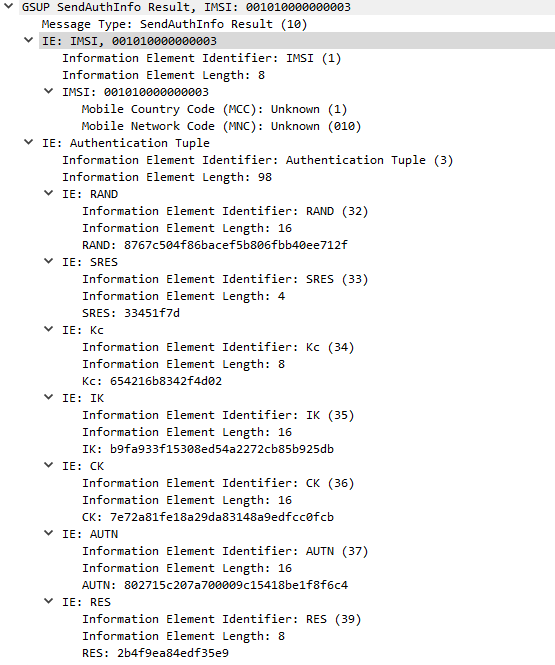
When a user wants to authenticate, the HSS network takes a Random key (RAND) and mixes it with the secret key (K) to generate a Signed Response called SRES. The network sends the RAND key to the subscriber, and their SIM takes the secret key (K) and mixes it with the RAND value from the network, before sending their signed response (SRES) back to the network. If the SRES sent by the subscriber matches the SRES generated by the HSS, then the user is authenticated. The set of keys used for one authentication session is referred to as an Authentication Vector or Authentication Tuple.
In Osmocom the generation of Authentication Tuples is requested in the GSUP “SendAuthInfo” request, and responded to by the “SendAuthInfoResponse” sent to the HLR by the MSC.
Side note about GSM Security
In a GSM setting the network only authenticates the subscribers, the subscribers don’t authenticate the network. In practice, this means there’s no way to verify in GSM if the network you’re connected to is the network it’s claiming to be.
Due to this shortfall and the cryptographic weakness in A5/x algorithm, 3GPP specified the AKA algorithm for mutual network authentication in 3G/UMTS networks.
Technically the generation of Authentication Vectors is handled by an Authentication Center (AuC) however OsomoHLR has an internal AuC that handles this internally.
Location Tracking
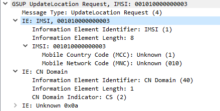
After a user has authenticated, the MSC sends an UpdateLocationRequest via GSUP to the HLR to let it know the current location of the subscriber is served by that MSC.
The Update Location Request is sent at the start of the session, periodic Update Location Requests can be sent based on the timers configured, and a Cancel Location Request can be sent when the subscriber disconnects from the MSC.
Subscriber Data Information
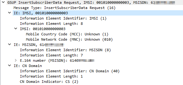
When the Update Location Request has been sent by the MSC, the HLR sends the MSC the subscriber’s info, and the MSC copies it to it’s own internal HLR called a Visitor Location Register (VLR). The VLR means the MSC doesn’t need to keep querying user data from the HLR.
This is again requseted by the MSC to the HLR via a GSUP request InsertSubscriberData Request which contains:
Subscriber’s IMSI
Subscriber’s MSISDN (Phone number)
Allowed Domains (CS/PS)
Note: In production GSM networks TCAP/MAP is used for communication between the HLR and the MSC. Osmocom uses GSUP for carrying this data instead.
Equipment Identity Register
Because mobiles are expensive they’ve historically been a target for theft.
To try and mitigate this GSMA encourages carriers to implement an Equipment Identity Register (EIR).
The EIR is essentially a database containing IMEIs (The Identifiers of Mobiles / Terminals) and permitting / denying access to the network based on the IMEI.
The idea being if a mobile device / terminal is stolen, it’s IMEI is blacklisted in the EIR and regardless of what SIM is put into it, it’s not permitted to access the network.
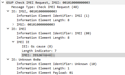
When a device connects to the network if configured the MSC will query the EIR (On the HLR in our case) with a Check IMEI Request, and will get a Check IMEI Result either permitting or denying access to the network.
Unfortunately, there is no global stolen IMEI database, meaning if a device is stolen and blocked on MNO X’s network, it may still work on MNO Y’s network if they don’t share stolen IMEI data.
Starting & Configuring OsmoHLR
We actually installed OmsoHLR in the post on Base Station Controllers, so we’ll just need to start the daemon / service:
systemctl start osmo-hlr
I’m going to enable the EIR functionality of the HSS by changing the config of the HLR, this is optional but it’s useful to use the EIR functionality.
Like with our other network elements we’ll use Tenet to interactively configure this one,
But before we go adding subscribers, let’s talk about SIMs.
Okay, I’ve written a lot about SIMs before, but there’s still more to talk about!
There’s really only one peice of information from your SIM we require to add the subscriber to the HLR, and that’s the IMSI – The unique identifier of the subscriber on the SIM. You can typically view the IMSI from your mobile device / terminal.
So I’ve created a subscriber with IMSI 001010000000004 in the HSS and assigned an MSISDN (phone number).
Optionally, if you’re using SIM cards you can program you can set the Ki / K key for authentication using the update aud2g function, if not you can skip that step.
And with that we’ve added our first subscriber, lather rinse repeat with any additional subscribers / SIMs you want to provision.
By default subscribers created using this method have access to both Circuit Switched (Voice and SMS) and Packet Switched (Data) networks. (We haven’t configured Packet Switched services yet)
If you’d like to restrict access to one, both or none of the above options, you can do that by using the subscriber update command to set the services available to those subscribers.
OsmoHLR# subscriber id 3 update network-access-mode cs+ps
OsmoHLR# subscriber id 3 update network-access-mode cs
OsmoHLR# subscriber id 3 update network-access-mode ps
OsmoHLR# subscriber id 3 update network-access-mode none
Creating Subscribers Programmatically
In reality if you’re trying to operate a network it’s not feasible to manually add each subscriber as needed.
If you’re buying SIMs in bulk preconfigured you’ll get sent a file containing the IMSI and Crypto values of each card, and you’d ingest that into your HLR.
We’ve used the Osmocom VTY / Telnet interface in quite a few posts now (hopefully you’re getting comfortable with it) but there’s another interface most Osmocom software has – the Osmocom Control Interface – aimed at providing a uniform way to interface external scripts / programs with Osmocom.
For most scenarios you would pre-provision each SIM in the HLR, if the SIM’s IMSI isn’t in the HLR then it’s access is rejected. However there are some scenarios where you may want to allow anyone to access the network, in this scenario Osmo-HLR features a “Create Subscribers on Demand” function.
This may be useful if you’re setting up a network where you don’t control the SIMs for example.
Let’s say we want to automatically create users with access to voice & data services and assign a 10 digit MSISDN for that subscriber, we can do that with:
Then if you wish to grant access to these users you can use the subscriber update network-access-mode method we talked about earlier to allow services for that user.
Packet Capture
To give some context I’ve attached a packet capture of the connection from the MSC to the HLR for some attach procedures on my lab network.
We’ll edit the oml remote-ip to the IP of the server running your BSC, if you’re running on on the same machine you can leave it as localhost (127.0.0.1).
Next up we’ll set the Unit-ID of the BTS, this identifies the BTS inside the BSC,
I’ll set it to unit-id 1234 by changing ipa unit-id 1234 0
Finally we’ll change the logging config to show everything by changing it to:
log stderr
 logging filter all 1
!
Next up we’ll configure the BTS on the BSC
BSC Provisioning
This is essentially a copy of the provisioning process we followed in the last post, the only difference is we’ll use BTS 2 (as BTS 1 is setup for our Virtual BTS) in the config, and set the few different identifier such as the ipa unit id for the SDR based BTS.
Before we start the SDR based BTS it’s probably best to have 3 terminals open,
One logged into Osmo-BSC with logging enabled (see the last post for info on how to do that).
We’ll start another terminal for running the TRX modem / Layer 1 interface:
osmo-trx-lms -C /etc/osmocom/osmo-trx-lms.cfg
And in another new terminal we’ll start the BTS side;
osmo-bts-trx -c /etc/osmocom/osmo-bts-trx.cfg
All going well our terminal with Osmo-BSC should report the connection:
OsmoBSC#
<0016> input/ipa.c:287 0.0.0.0:3003 accept()ed new link from 10.0.1.252:39595
<0003> osmo_bsc_main.c:291 bootstrapping RSL for BTS/TRX (2/0) on ARFCN 875 using MCC-MNC 001-01 LAC=1234 CID=1234 BSIC=12
And the osmo-trx-lms and osmo-bts-trx windows should have data flying by at a rate of knots.
Verifying Cell Operation
If all is going to plan, our SDR is connected to our machine via osmo-trx-lms which is acting as a modem for osmo-bts-trx which is now connected to the BSC. Lot to go through, but it gets easier from here.
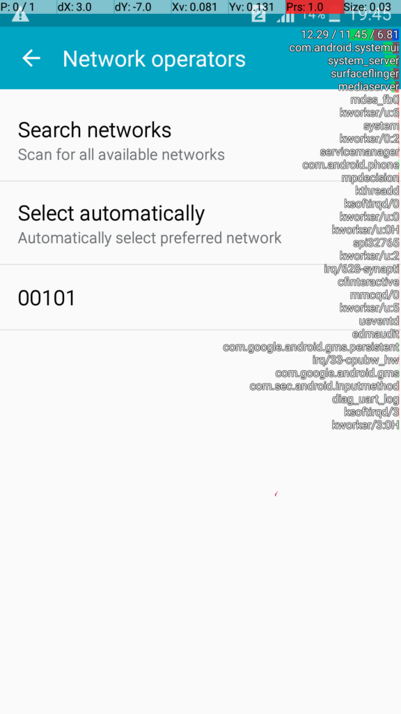
Let’s run a scan of the networks on our phone. I found putting mine on GSM only before scanning for networks meant it popped up a heck of a lot faster.
And lo, there it is.
Our cell is online and broadcasting it’s info. You won’t be able to connect to it at this stage as we’ve still got a few more steps to go.
In the next post we’ll introduce the Home Location Register and then the MSC.
Osmo-BSC accepts Abis over IP connections from a number of different sources,
There’s a list of supported BTS hardware that can talk out of the box to the Osmo-BSC, such as the Ericsson RBS series, ip.access nanoBTS, Nokia and Siemens units and even a virtual BTS so you can simulate the connections.
If you’re using any of these premade BTS hardware options, or osmo-bts-virtual, you probably just need to setup the basics on your BTS and point it to your BSC, end of story.
The below post will touch on using common SDR hardware to act as our BTS. If you’re not using SDR hardware you can just skip ahead to the next post on BSCs.
But, if you’re in the same boat as me, without any commercial BTS / RAN hardware, we’ll be setting it up by using an SDR platforms (In my case LimeSDR) and that’s what this tutorial will focus on.
Osmo-TRX
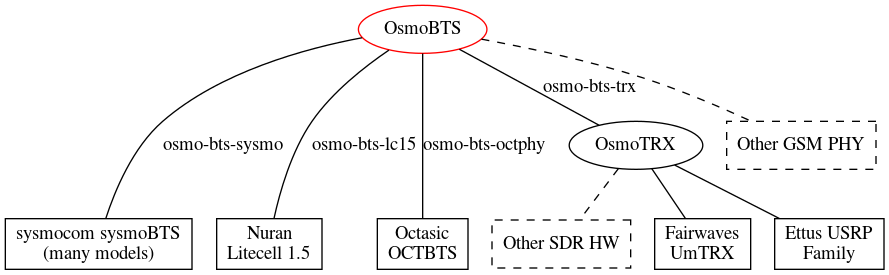
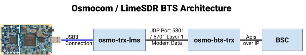
In order to bring in a large array of SDR hardware, Osmocom have introduced Osmo-TRX, which handles the Layer 1 physical layer of the BTS, and connects to Osmo-BTS which serves as the BTS and talks Abis over IP to the MSC.
Certain hardware can talk directly to Osmo-BTS, but we’re going to rely on Osmo-TRX to act as the middleman between our SDR hardware and the BTS.
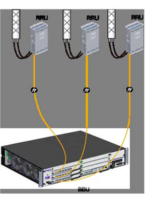
The above diagram from the Osmocom wiki shows how this fits together with generic SDR platforms, here’s how it fits together for us:
osmo-trx-lms will take care of the SDR side of the equation, pretty much serving as a modem and sending everything it gets on the Uu interface to osmo-bts-trx over UDP, and everything it receives from osmo-bts-trx over UDP it sends out the Uu interface.
osmo-bts-trx will then setup an Abis over IP connection to our BSC.
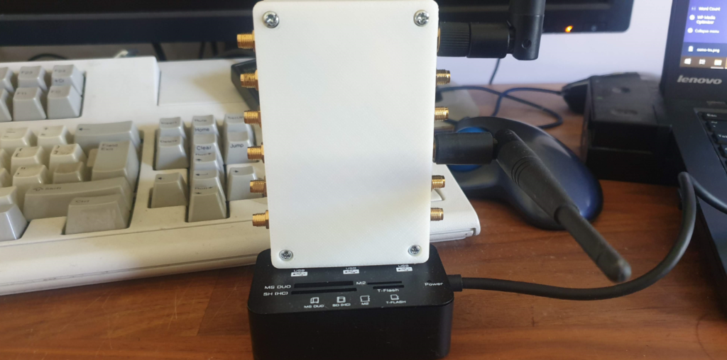
The LimeSDR
My ever growing collection of SDR hardware now includes a LimeSDR which I’ll be using for this series.
Before we can get too far we’ve got to setup the prerequisites for the LimeSDR to be able to interface with Osmo-TRX.
Osmocom now provide a binary for interfacing with LimeSDR boards directly, instead of having to use the UHD abstraction. This is a much cleaner way of interfacing with the boards and the path I’ll be taking.
Software Install
For this tutorial series I’ll be using Ubuntu 18.04 and trying where possible to use packages from Repos instead of compiling from source.
LimeSuite provides the drives and utilities for interfacing with the LimeSDR.
So now we’ve got two pieces of the puzzle, it’s time to connect the SDR to Osmo-TRX-LMS and connect Osmo-TRX-LMS to Osmo-BTS-TRX.
We’ll begin by running Osmo-TRX-LMS to connect to the LimeSDR and encapsulate the Uu data into UDP packets we send to Osmo-BTS-TRX.
Config files for Osmocom are installed in /etc/osmocom/ so we’ll run everything from that directory.
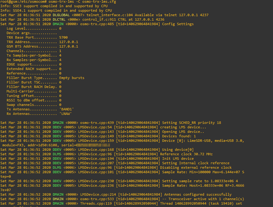
osmo-trx-lms -C osmo-trx-lms.cfg
If all was successful you’ll see something similar to what I’ve got below, showing Osmo-TRX-LMS has connected to the SDR and is ready to go.
But if you go scanning the airwaves now, you won’t see any data coming out of the SDR’s transmitter.
That’s because Osmo-TRX-LMS needs to connect to Osmo-BTS-TRX,
We’ll leave Osmo-TRX-LMS running, so let’s open up another session and start Osmo-BTS-TRX.
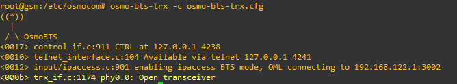
osmo-bts-trx -c osmo-bts-trx.cfg
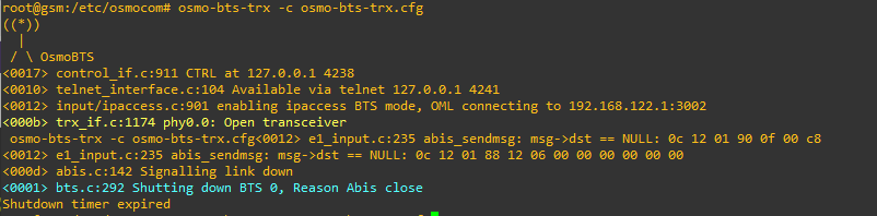
You’ll see for starters that it’s Opened our transceiver (hooray),
You’ll see this reflected in the Osmo-TRX-LMS stdout, but it’ll show the poweroff command has been sent to it, so what gives?
Well, the answer becomes clear if you leave Osmo-BTS-TRX running for a minute or two,
Eventually the process stops, reporting:
<000d> abis.c:142 Signalling link down
<0001> bts.c:292 Shutting down BTS 0, Reason Abis close
So what’s going on? In the same way we saw our Virtual BTS shut itself down, without a connection to the BSC (Via the Abis interface) the BTS will shut itself down, as it’s not able to run on it’s own.
This took me a shamefully long time to work out that’s why it was stopping…
In our next post we’ll introduce our BSC and provision a BTS on it.
So in our last post we finished setting up a Base Transceiver Station (BTS) but it’s no use unless it can home itself to a Base Station Controller (BSC).
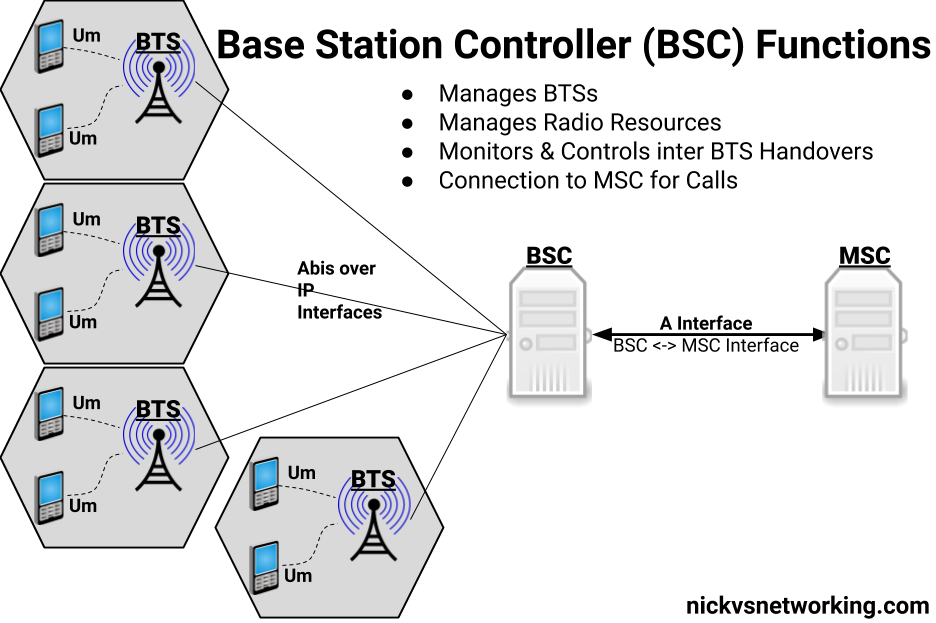
So what does a BSC do?
The BSC acts as a central controller for one or more BTS.
In practice this means the BSC configures most of the parameters on the BTS and brings each one up onto the air when they’re ready.
The BSC monitors measurements from users to work out when to hand off from one BTS to neighboring BTS,
The BSC also handles the allocation of radio channels and radio resources across the BTSs it manages.
In short, it does pretty much everything radio related for the BTS except transmitting and receiving data over the Air (Um) interface.
As well as managing the BTS under it, the other other equally important role of the BSC is to provide connectivity to the rest of the GSM network, by connecting to a Mobile Switching Center (MSC) which handles calls to and from our mobile subscribers and authenticating them.
By acting as a funnel of sorts, the MSC only needs a connection to each BSC instead of to each BTS (Which would be an impractically large number of connections)
Osmo BSC Install
Osmocom have their own BSC – Aptly called Osmo-BSC.
Installation is pretty straightforward, assuage you’ve got the Osmocom repo in your sources list:
apt-get install osmo-bsc
systemctl stop osmo-bsc
In order to serve the BTSs it controls, Osmo-BSC relies on connectivity to a Mobile Switching Center (MSC), which in turn connects to a HLR (Home Location Register). The BSC and MSC communicate via SS7, and the routing is done by a Signal Transfer Points (STP).
We’ll go into each of these elements in more detail, but in order to bring our BSC up in a useful way, we’ll need to install and start these applications.
We’ll talk about the MSC, the basics of SS7 / Sigtran and the HLR later in the series, but for now we’ll blindly install and start them:
We’ll come back and cover each of these elements in more detail in due course.
Osmo Config – Telnet Interactive Terminal
So now we’ve got the BSC installed we’ve pointed our BTS at the IP of the BSC, we’ll need to get osmo-bsc running and add the config for our new BTS.
Instead of working with the text file we’ll start the service and work on it through Telnet, like we would for many common network devices.
Osmo-BSC listens on port 4242, so we’ll start Osmo-BSC and connect to it via Telnet:
systemctl start osmo-bsc
telnet localhost 4242
The interface should come pretty naturally to anyone who’s spent much time setting up other network devices, a lot of the commands are similar and yes – tab completion is a thing!
We’ll start by enabling logging so we can get an idea of what’s going on:
OsmoBSC> enable
OsmoBSC# logging enable
OsmoBSC# logging filter all 1
OsmoBSC# logging color 1
Next up in a new terminal / SSH session, we’ll run our virtual BTS again;
osmo-bts-virtual -c osmo-bts-virtual.cfg
This time we’ll get a different output from the BTS when we try to start it:
root@gsm-bts:/etc/osmocom# osmo-bts-virtual -c osmo-bts-virtual.cfg
 ((*))
   |
  / \ OsmoBTS
<0010> telnet_interface.c:104 Available via telnet 127.0.0.1 4241
<0012> input/ipaccess.c:901 enabling ipaccess BTS mode, OML connecting to 127.0.0.1:3002
<0012> input/ipa.c:128 127.0.0.1:3002 connection done
<0012> input/ipaccess.c:724 received ID_GET for unit ID 4242/0/0
<0012> input/ipa.c:63 127.0.0.1:3002 lost connection with server
<000d> abis.c:142 Signalling link down
<000d> abis.c:156 OML link was closed early within 0 seconds. If this situation persists, please check your BTS and BSC configuration files for errors. A common error is a mismatch between unit_id configuration parameters of BTS and BSC.

root@gsm-bts:/etc/osmocom#
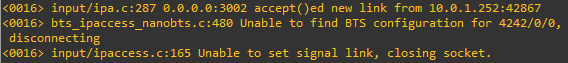
We’ll also see errors in the terminal on the BSC too:
<0016> input/ipa.c:287 0.0.0.0:3002 accept()ed new link from 10.0.1.252:39383
<0016> bts_ipaccess_nanobts.c:480 Unable to find BTS configuration for 4242/0/0, disconnecting
So what’s happening here?
Well our virtual BTS is trying to connect to our BSC, and this time it’s able to, but our BSC doesn’t have any config in place for that BTS, so the BSC has rejected the connection.
So now we’ve got to configure a the BSC to recognise our BTS.
Provisioning a new BTS in the BSC
So as to keep this tutorial generic enough for anyone to follow along, we’re first going to configure a virtual BTS in our BSC to begin with. I wrote about installing Osmo-BTS-Virtual in this post.
We can get the information about the rejected BTS connection attempt from the BSC terminal:
OsmoBSC# show rejected-bts
 Date                Site ID BTS ID IP
2020-03-29 01:32:37    4242      0      10.0.1.252
So we know the Site-ID is 4242 (we set it earlier) and the BTS ID for that site is 0, so let’s create a BTS in the BSC;
Well as we’re getting the majority of the smarts for the BTS from the BSC, we’ve got to tell the BSC all about how we want the BTS setup. (Believe it or not this is the most abridged setup I could muster.)
The type, IPA Unit ID, band and Cell Identity make up some of the parameters we need to identify the BTS (IPA Unit ID) and give it it’s basic identity parameters.
Next up in the trx 0 section we set the contents of the 8 GSM timeslots. Our first time slot we configure as CCCH+SDCCH4 meaning the first timeslot will contain the Common Control Channel and 4 Standalone dedicated control channels, used for signalling, while the reamining 7 timeslots will be used with traffic channels for full-rate speech (TCH/F).
It’s important that what we tell the BSC the capabilities of the BTS are match the actual capabilities of the BTS. For example there’s no point configuring GPRS or EDGE support on the BSC if the BTS doesn’t support it.
If you’ve got logging enabled when the BTS connects to the BSC you’ll see errors listing the features mismatch between the two.
As you can imagine there’s better options than this for adding BTS in bulk – Osmocom Control Interface exposes these functions in an API like way, but before you start on network orchestration it’s good to know the basics.
Connecting the BTS to the BSC
So let’s go ahead and connect our BTS to the BSC.
If you’ve closed the BSC terminal since we enabled logging you’ll need to enable it again:
OsmoBSC> logging enable
OsmoBSC> logging filter all 1
OsmoBSC> logging color 1
And next up we’ll try and start the BTS again:
root@gsm-bts:/etc/osmocom# osmo-bts-virtual -c osmo-bts-virtual.cfg
 ((*))
   |
  / \ OsmoBTS
<0010> telnet_interface.c:104 Available via telnet 127.0.0.1 4241
<0012> input/ipaccess.c:901 enabling ipaccess BTS mode, OML connecting to 127.0.0.1:3002
<0012> input/ipa.c:128 127.0.0.1:3002 connection done
<0012> input/ipaccess.c:724 received ID_GET for unit ID 4242/0/0
And on the BSC you’ll see roughly the same thing:
OsmoBSC#
<0016> input/ipa.c:287 0.0.0.0:3002 accept()ed new link from 127.0.0.1:40193
<0004> abis_nm.c:490 BTS1 reported variant: omso-bts-virtual
<0004> abis_nm.c:578 OC=BASEBAND-TRANSCEIVER(04) INST=(00,00,ff): BTS1: ARI reported sw[0/1]: TRX_PHY_VERSION is Unknown
<0016> input/ipa.c:287 0.0.0.0:3003 accept()ed new link from 127.0.0.1:44053
<0003> osmo_bsc_main.c:291 bootstrapping RSL for BTS/TRX (1/0) on ARFCN 0 using MCC-MNC 001-01 LAC=4242 CID=4242 BSIC=42
If you’ve made it this far, congratulations. Our virtual BTS is now connected to our BSC – If it wasn’t virtual we’d be on the air!
So in the next post we’ll setup our SDR hardware as a BTS, then provision it on the BSC, and then our cell will be on the air.
So this series of posts will focus on using Osmocom software to create a GSM network, so let’s get some Osmocom software installed, and talk about how we run and configure each network element / node.
Osmocom Packages
For this tutorial series I’ll be using Ubuntu 18.04 and trying where possible to use packages from Repos instead of compiling from source.
This will get the Osmocom key added to your package manager and the Osmocom sources in apt ready for us to install.
To get started we’ll install a virtual BTS. This virtual BTS won’t simulate the Um (air) interface, but it will simulate the Abis interface towards the BSC so we can configure this virtual BTS in our BSC.
Installation is pretty straightforward:
apt-get install osmo-bts-virtual
By default Osmocom software runs as a daemon in systemctl, we’ll disable and stop this behaviour for now so we can better understand it running in the foreground:
If you have a look in /etc/osmocom/ you’ll see .cfg files that contain our config in text files.
But that’s not the only way (or even the recommended way) that we’ll put together the config for Osmocom software, but we’ll get started by editing the config file manually.
We’ll start by setting a Unit ID of the BTS and setting the IP of the BSC.
cd /etc/osmocom/
vi osmo-bts-virtual.cfg
We’ll edit the oml remote-ip to point to the IP of the server that will run our BSC, if you’re planning on running the BTS and BSC on the same machine you can leave it as localhost (127.0.0.1).
Next up we’ll set the Unit-ID of the BTS, this identifies the BTS inside the BSC,
I’ll set it to unit-id 4242 by changing ipa unit-id 4242 0
Finally we’ll change the logging config to show everything by changing it to:
log stderr
 logging filter all 1
!
So that’s it in terms of config for our virtual BTS through text files, so we’ll save the file and try starting up osmo-bts-virtual.
osmo-bts-virtual -c osmo-bts-virtual.cfg
You should get a result similar to this:
root@gsm-bts:/etc/osmocom# osmo-bts-virtual -c osmo-bts-virtual.cfg
 ((*))
   |
  / \ OsmoBTS
<0010> telnet_interface.c:104 Available via telnet 127.0.0.1 4241
<0012> input/ipaccess.c:901 enabling ipaccess BTS mode, OML connecting to 127.0.0.1:3002
<000d> abis.c:142 Signalling link down
<0001> bts.c:292 Shutting down BTS 0, Reason Abis close
Shutdown timer expired

root@gsm-bts:/etc/osmocom#
So what are we seeing here?
Well Osmo-BTS-Virtual is trying to bring up it’s Abis interface but it’s not getting a connection to the the BSC (We haven’t set one up yet). No connection to a BSC means the BTS won’t go on the air as it doesn’t have any processing for itself, so it eventually times out and shuts down.
In the next post we’ll move from using osmo-bts-virtual to using a SDR to run Osmo-BTS. If you’re using commercial RAN hardware, or just playing along without any RAN, skip straight to the post on Base Station Controllers where we’ll pick up again adding our Virtual BTS to the BSC.
By far the most visable part of any mobile network (apart from your phone!) is the Base (Transciver) Stations.
Dotted around the countryside, on masts, towers and monopoles, whether you notice them or not, base stations are everywhere.
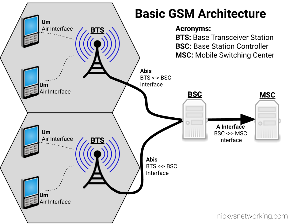
The Architecture
The RF side of LTE has an eNodeB, which is a smart device. – You connect it to a TCP/IP network, it establishes a connection with your MME(s) and away you go.
A GSM BTS (Base Transceiver Station) isn’t all that clever…
The BTS is a similar to the WiFi access points that talk to a centralised controller for all their thinking. A BTS gets most of its brains from elsewhere and essentially just handles the TX/RX of baseband data.
That elsewhere is the BSC – Base Station Controller. Each BTS connects to a BSC, and a BSC would typically control a number of BTS.
We’ll explore the BSC and it’s connections in depth, but I’ve put together a basic diagram of how everything fits together below.
Basic GSM Access Architecture
Um Interface
The Um interface is the Air Interface of GSM. It’s what takes the data and sends it out “over the air”.
There’s a lot to know about air interfaces, and I know very little. What I do know is I need to set the Um interface to use a frequency band my mobile phone supports (so I can see and connect to the network).
The Abis Interface
The fact that GSM was first deployed in 1991, explains why the Abis interface used ISDN E1/T1 TDM links to connect the Base Transceiver Stations (BTSs) to the Base Station Controller (BSC).
While now looking back you may ask why TCP/IP wasn’t used for the Abis interface, keep in mind that Windows 95 was the first version to include TCP/IP support, and that gives you an idea of the state of play. ISDN is very reliable and was well known in the telco space at that time.
I no longer have any ISDN hardware, so for me this is all going to be built using packet switched networks working as circuit switched.
Osmocom does have support for E1/T1 interfaces, so if you’ve got BTS hardware that only communicates over TDM links, that’s an option too.
GSMA never wrote a standard for taking Abis over IP, so as such each vendor has implemented it differently.
With all the brains for the BTS residing in the BSC, there’s a need to control the BTS from the BSC. The Operation and Maintenance Link (OML) is a protocol for changing certain parameters of the BTS from the BSC.
A prime example of use of the OML would be the BSC turning the BTS off/on.
We’ll see a tiny bit of OML usage in the next post, just for turning the BTS off and on.
So let’s put this into practice and setup a virtual BTS with Osmocom.