Tag Archives: BTS3900

Huawei BBU 3900 Architecture

Huawei BTS3900 eNB Configuration

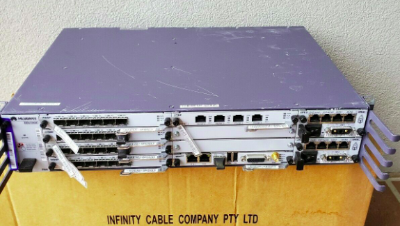
Last year I purchased a cheap second hand Huawei macro base station – there’s lots of these on the market at the moment due to the fact they’re being replaced in many countries.

I’m using it in my lab environment, and as such the config I’ve got is very “bare bones” and basic. Keep in mind if you’re looking to deploy a Macro eNodeB in production, you may need more than just a blog post to get everything tuned and functioning properly…

In this post we’ll cover setting up a Huawei BTS3900 eNodeB from scratch, using the MML interface, without relying on the U2020 management tool.

Obviously the details I setup (IP Addressing, PLMN and RF parameters) are going to be different to what you’re configuring, so keep that in mind, where I’ve got my MME Addresses, site IDs, TACs, IP Addresses, RFUs, etc, you’ll need to substitute your own values.

A word on Cabinets

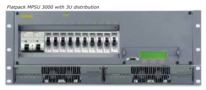
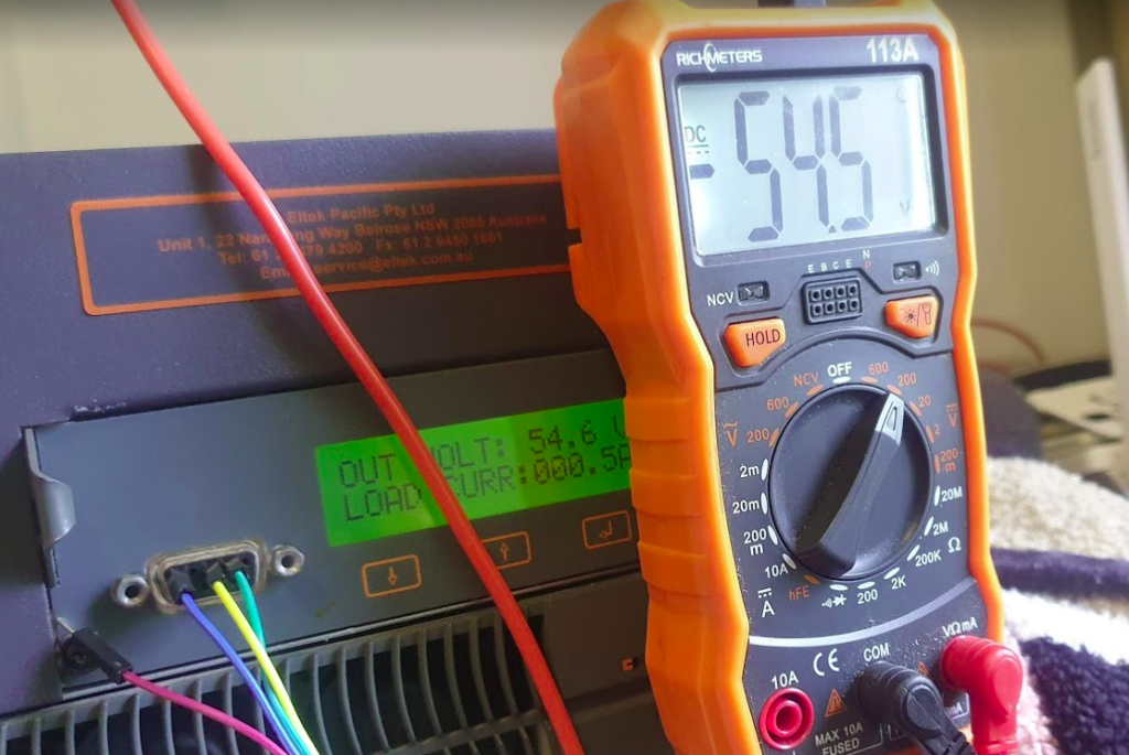
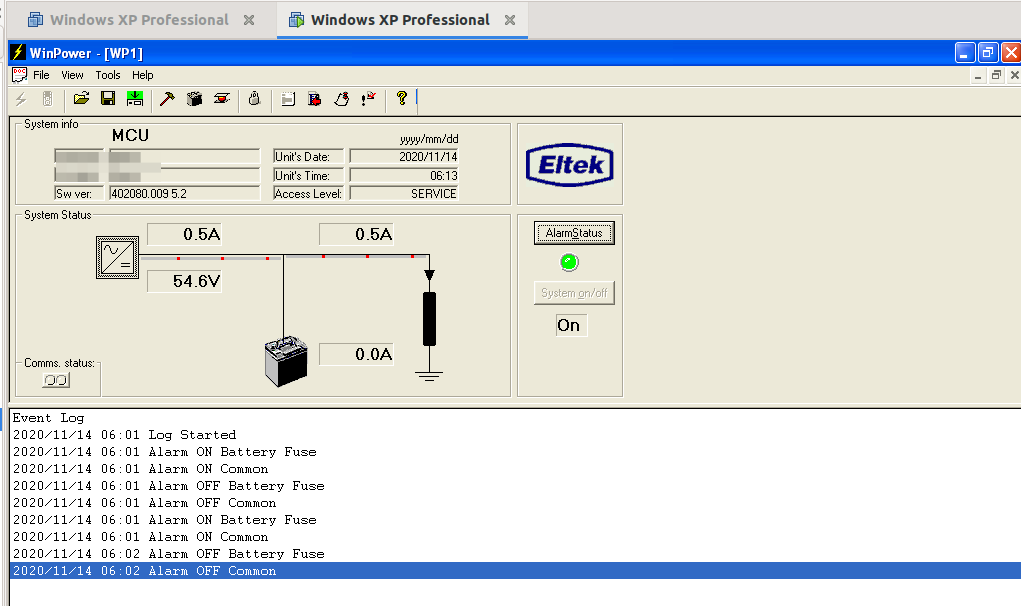
Typically these eNodeBs are shipped in cabinets, that contain the power supplies, alarm / environmental monitoring, power distribution, etc.

Early on in the setup process we’ll be setting the cabinet types we’ve got, and then later on we’ll tell the system what we have installed in which slots.

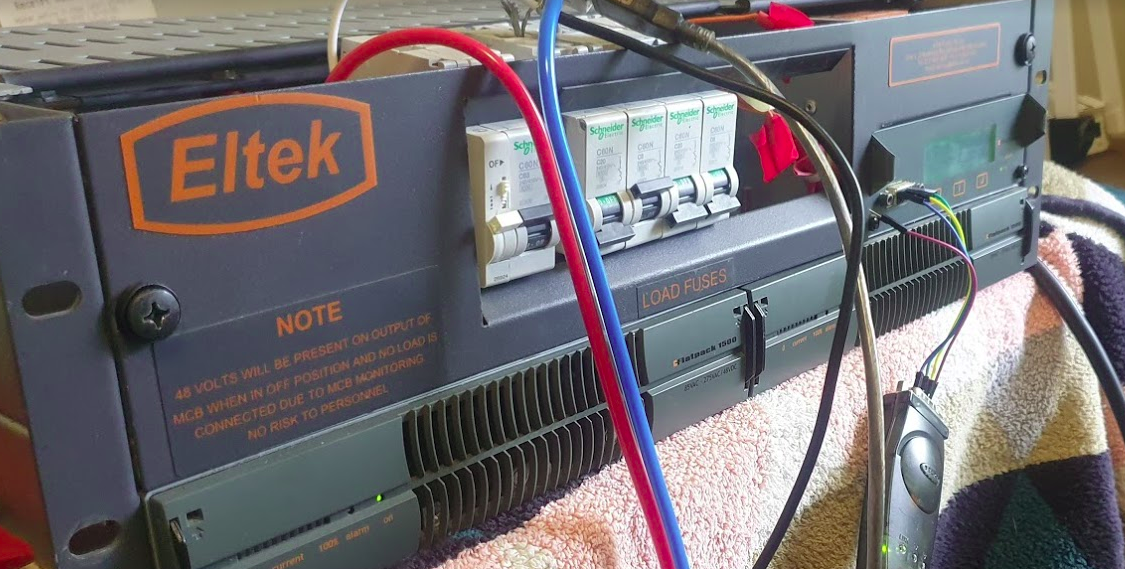
This is fine if you have a cabinet and know the type, but in my case at least I don’t have a cabinet manufactured by Huawei, just a rack with some kit mounted in it.

This is OK, but it leads to a few gotchas I need to add a cabinet (even though it doesn’t physically exist) and when I setup my RRUs I need to define what cabinet, slot and subrack it’s in, even though it isn’t in any. Keep this in mind as we go along and define the position of the equipment, that if you’re not using a real-world cabinet, the values mean nothing, but need to be kept consistent.

The Basics

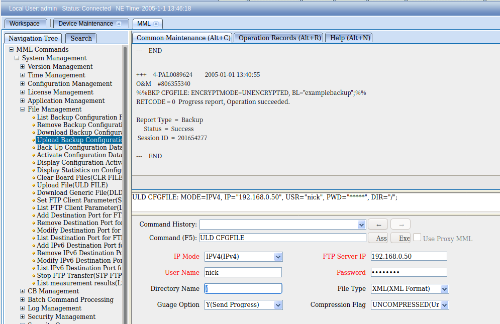
Before we get started, familiarise yourself with the Huawei MML we’ll use for configuring the unit, and log into the Web UI and bring up an MML shell.

To begin we’ll need to setup the basics, by disabling DHCP and setting an local IP Address for the unit.

 SET DHCPSW: SWITCH=DISABLE;
 SET LOCALIP: IP="192.168.5.234", MASK="255.255.248.0";

Obviously your IP address details will be different.
Next we’ll add an eNodeB function, the LMPT / UMPT can have multiple functions and multiple eNodeBs hosted on the same hardware, but in our case we’re just going to configure one:

 ADD ENODEBFUNCTION: eNodeBFunctionName="LTE", ApplicationRef=1, eNodeBId=9527;
 SET NE: NENAME="HUAWEI", LOCATION="NewSite", DID="NewSite12345", SITENAME="NewSite1", USERLABEL="NewInitSite";
 ADD LOCATION: LOCATIONNAME="NewSite", GCDF=Degree, LATITUDEDEGFORMAT=0, LONGITUDEDEGFORMAT=0; 

Again, your eNodeB ID, location, site name, etc, are all going to be different, as will your location.

Next we’ll set the system to maintenance mode (MNTMODE), so we can make changes on the fly (this takes the eNB off the air, but we’re already off the air), you’ll need to adjust the start and end times to reflect the current time for the start time, and end time to be after you’re done setting all this up.

 SET MNTMODE: MNTMode=INSTALL, ST=2013&09&20&15&00&00, ET=2013&09&25&15&00&00, MMSetRemark="NewSite Install";

Next we’ll set the operator details, this is the PLMN of the eNodeB, and create a new tracking area.

 ADD CNOPERATOR: CnOperatorId=0, CnOperatorName="NickTest", CnOperatorType=CNOPERATOR_PRIMARY, Mcc="001", Mnc="01";
ADD CNOPERATORTA: TrackingAreaId=0, CnOperatorId=0, Tac=1;

Next we’ll be setting and populating the cabinets I mentioned earlier. I’ll be telling the unit it’s inside a APM30 (Cabinet 0), and in Cabinet Number 0, Subrack 0, is a BBU3900.

 //To modify the cabinet type, run the following command:
ADD CABINET:CN=0,TYPE=APM30;
//Add a BBU3900 subrack, run the following command:
ADD SUBRACK:CN=0,SRN=0,TYPE=BBU3900;
//To configure boards and RF datas, run the following commands:

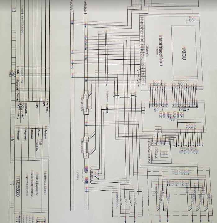
And inside the BBU3900 there’s some cards of course, and each card has as slot, as per the drawing below.

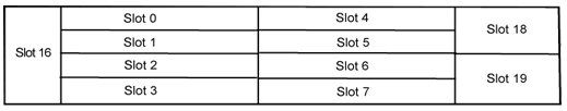
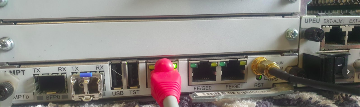
In my environment I’ve got a LMPT in slot 7, and a LBBP in Slot 3. There’s a fan and a UPEU too, so:
We’ll add a board in Slot No. 7, of type LMPT,
We’ll add a board in Slot No. 3, of type LBBP working on FDD,
We’ll add a fan board in Slot No. 16, and a UPEU in Slot No. 18.

 ADD BRD:SN=7,BT=LMPT;
 ADD BRD:CN=0,SRN=0,SN=3,BT=LBBP,WM=TDD;
 ADD BRD:CN=0,SRN=0,SN=16,BT=FAN;
 ADD BRD:CN=0,SRN=0,SN=18,BT=UPEU;

Huawei publish design guides for which cards should be in which slots, the general rule is that your LMPT / UMPT card goes in Slot 7, with your BBP cards (UBBP or LBBP) in slots 3, then 2, then 1, then 0. Fans and UPEUs can only go in the slots designed to fit them, so that makes it a bit easier.

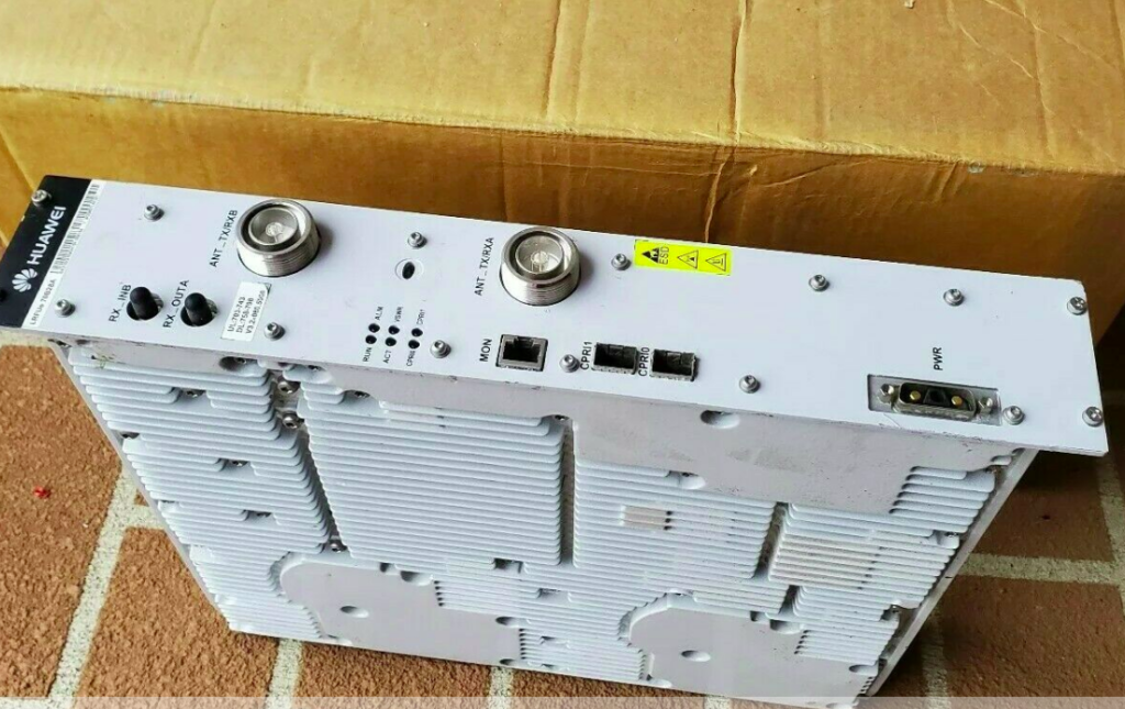
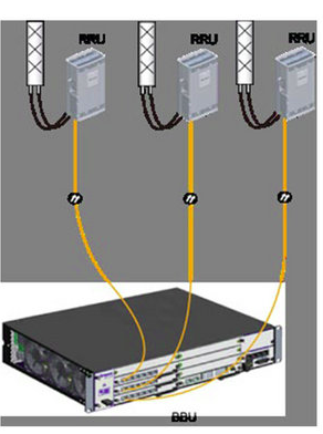
Next we’ll need to setup our RRUs, for this we’ll need to setup an RRU chain, which is the Huawei term for the CPRI links and add an RRU into it:

ADD RRUCHAIN:RCN=10,TT=CHAIN,BM=COLD,HSRN=70,HSN=0,HPN=0;

ADD RRU:CN=0,SRN=60,SN=0,TP=BRANCH,RCN=10,PS=0,RT=MPMU,RS=TDL,RXNUM=0,TXNUM=0;

With our RRU chains defined, we’ll need to setup our transport network to get the traffic back to the S-GW / MME:

SET ETHPORT: SN=7, SBT=BASE_BOARD, PA=COPPER, SPEED=AUTO, DUPLEX=AUTO;
ADD DEVIP: SN=7, SBT=BASE_BOARD, PT=ETH, PN=0, IP="10.10.10.67", MASK="255.255.255.0";
ADD IPRT: RTIDX=0, SN=7, SBT=BASE_BOARD, DSTIP="10.166.1.251", DSTMASK="255.255.255.255", RTTYPE=NEXTHOP, NEXTHOP="10.10.10.1"; 
ADD IPRT: RTIDX=1, SN=7, SBT=BASE_BOARD, DSTIP="10.4.3.3", DSTMASK="255.255.255.255", RTTYPE=NEXTHOP, NEXTHOP="10.10.10.1"; 
ADD IPRT: RTIDX=2, SN=7, SBT=BASE_BOARD, DSTIP="10.3.3.3", DSTMASK="255.255.255.255", RTTYPE=NEXTHOP, NEXTHOP="10.10.10.1";
ADD IPRT: RTIDX=3, SN=7, SBT=BASE_BOARD, DSTIP="10.60.60.60", DSTMASK="255.255.255.255", RTTYPE=NEXTHOP, NEXTHOP="10.10.10.1";
ADD OMCH: IP="10.10.10.67", MASK="255.255.255.0", PEERIP="10.166.1.251", PEERMASK="255.255.255.255", BEAR=IPV4, BRT=YES, RTIDX=0, BINDSECONDARYRT=NO, CHECKTYPE=NONE;
ADD VLANMAP: NEXTHOPIP="10.10.10.1", MASK="255.255.248.0", VLANMODE=SINGLEVLAN, VLANID=3721, SETPRIO=DISABLE; 
ADD SCTPTEMPLATE: SCTPTEMPLATEID=0, SWITCHBACKFLAG=ENABLE;
ADD SCTPHOST: SCTPHOSTID=0, IPVERSION=IPv4, SIGIP1V4="10.10.10.67", SIGIP1SECSWITCH=DISABLE, SIGIP2SECSWITCH=DISABLE, PN=2000, SCTPTEMPLATEID=0;
ADD SCTPPEER: SCTPPEERID=0, IPVERSION=IPv4, SIGIP1V4="10.3.3.3", SIGIP1SECSWITCH=DISABLE, SIGIP2SECSWITCH=DISABLE, PN=2000;
ADD USERPLANEHOST: UPHOSTID=0, IPVERSION=IPv4, LOCIPV4="10.10.10.67", IPSECSWITCH=DISABLE;
ADD EPGROUP: EPGROUPID=0;
ADD SCTPHOST2EPGRP: EPGROUPID=0, SCTPHOSTID=0; 
ADD SCTPPEER2EPGRP: EPGROUPID=0, SCTPPEERID=0;
ADD UPHOST2EPGRP: EPGROUPID=0, UPHOSTID=0;
ADD S1: S1Id=0, CnOperatorId=0, EpGroupCfgFlag=CP_UP_CFG, CpEpGroupId=0, UpEpGroupId=0;


We’ll need clocking and time as well, we’ll use NTP and GPS:

SET TIMESRC: TIMESRC=NTP; 
ADD NTPC: MODE=IPV4, IP="10.166.1.251", PORT=123, SYNCCYCLE=60, AUTHMODE=PLAIN; 
SET MASTERNTPS: MODE=IPV4, IP="10.166.1.251"; 
SET TZ: ZONET=GMT+0800, DST=NO;

ADD GPS: SRN=0, SN=7;
SET CLKMODE: MODE=MANUAL, CLKSRC=GPS, SRCNO=0;
SET CLKSYNCMODE:CLKSYNCMODE=TIME;

Next we’ll need to define a sector, sector equipment & cell, then link it to a sector equipment group:

ADD SECTOR:SECTORID=0,ANTNUM=2,ANT1CN=0,ANT1SRN=60,ANT1SN=255, ANT1N=R0A,ANT2CN=0,ANT2SRN=60,ANT2SN=255,ANT2N=R0B,CREATESECTOREQM=FALSE;

ADD SECTOREQM:SECTOREQMID=0,SECTORID=0,ANTNUM=2,ANT1CN=0, ANT1SRN=60,ANT1SN=255,ANT1N=R0A,ANTTYPE1=RXTX_MODE,ANT2CN=0,ANT2SRN=60,ANT2SN=255,ANT2N=R0B,ANTTYPE2=RXTX_MODE;

ADD CELL:LOCALCELLID=1,CELLNAME="CELL1",FREQBAND=41,ULEARFCNCFGIND=NOT_CFG,DLEARFCN=40340,ULBANDWIDTH=CELL_BW_N100,DLBANDWIDTH=CELL_BW_N100,CELLID=1,PHYCELLID=1,FDDTDDIND=CELL_TDD,SUBFRAMEASSIGNMENT=SA2,SPECIALSUBFRAMEPATTERNS=SSP5,ROOTSEQUENCEIDX=0,CUSTOMIZEDBANDWIDTHCFGIND=NOT_CFG,EMERGENCYAREAIDCFGIND=NOT_CFG,UEPOWERMAXCFGIND=NOT_CFG,MULTIRRUCELLFLAG=BOOLEAN_TRUE,MULTIRRUCELLMODE=MPRU_AGGREGATION, CPRICOMPRESSION=NORMAL_COMPRESSION,TXRXMODE=2T2R;

ADD EUSECTOREQMGROUP:LOCALCELLID=1,SECTOREQMGROUPID=1;
ADD EUSECTOREQMID2GROUP:LOCALCELLID=1,SECTOREQMGROUPID=1, SECTOREQMID=0;

Alright, now we can activate it:

//Modify the reference signal power.
MOD PDSCHCFG: LocalCellId=1, ReferenceSignalPwr=-81;

//Add an operator for the cell.
ADD CELLOP: LocalCellId=0, TrackingAreaId=0;

//Activate the cell.
ACT CELL: LocalCellId=1;

And lastly we can define some neighboring cells:

//Configure neighboring cells. 
ADD EUTRANINTERNFREQ: LocalCellId=1, DlEarfcn=3100, UlEarfcnCfgInd=NOT_CFG, CellReselPriorityCfgInd=NOT_CFG, SpeedDependSPCfgInd=NOT_CFG, MeasBandWidth=MBW100, PmaxCfgInd=NOT_CFG, QqualMinCfgInd=NOT_CFG;
ADD EUTRANEXTERNALCELL: Mcc="460", Mnc="02", eNodeBId=236, CellId=0, DlEarfcn=3100, UlEarfcnCfgInd=NOT_CFG, PhyCellId=236, Tac=33;
ADD EUTRANINTERFREQNCELL: LocalCellId=1, Mcc="460", Mnc="02", eNodeBId=236, CellId=0;

Huawei BBU 3900 Architecture

Huawei Baseband Cheat Sheet

Baseband Units (UBBP)

CardMax LTE Cells
UBBPd33×20 MHz 2T2R
UBBPd43×20 MHz 4T4R
UBBPd56×20 MHz 2T2R OR 3×20 MHz 4T4R
UBBPd66×20 MHz 4T4R
UBBPe13×20 MHz 2T2R
UBBPe23×20 MHz 4T4R
UBBPe36×20 MHz 2T2R OR 3×20 MHz 4T4R
UBBPe46×20 MHz 4T4R OR 3×20 MHz 8T8R
Max Cells in LTE FDD

Main Processing and Transmission (LMPT/UMPT)

In some instances two boards can be used together to double the max cells or max throughput values.

CardMax CellsMax Throughput
(at MAC Layer)
Max UEs
(In RRC Connected)
LMPT18 Cells (4T4R)Uplink 300Mbps
Downlink 450Mbps
5400
UMPTa36 Cells (4T4R)Aggregate 1.5Gbps10800
UMPTb136 Cells (4T4R)Aggregate 1.5Gbps10800
UMPTb236 Cells (4T4R)Aggregate 1.5Gbps10800
UMPTb336 Cells (4T4R)Aggregate 2Gbps10800
UMPTb936 Cells (4T4R)Aggregate 2Gbps10800
UMPTe72 Cells (4T4R)Aggregate 10Gbps14400

Enable GPS/GLONASS Sync on Huawei BTS3900

Our BTS is going to need an accurate clock source in order to run, so without access to crazy accurate Timing over Packet systems or TDM links to use as reference sources, I’ve opted to use the GPS/GLONASS receiver built into the LMPT card.

Add new GPS with ID 0 on LMPT in slot 7 of cabinet 1:

ADD GPS: GN=0, CN=1, SRN=7, CABLE_LEN=3, MODE=GPS/GLONASS;

Check GPS has sync (May take some time) using the Display GPS command;

DSP GPS: GN=0;

Assuming you’ve got an antenna connected and can see the sky, after ~10 minutes running the DSP GPS:; command again should show you an output like this:

+++    4-PAL0089624        2020-11-28 01:06:55
O&M    #806355684
%%DSP GPS: GN=0;%%
RETCODE = 0  Operation succeeded.

Display GPS State
-----------------
                 GPS Clock No.  =  0
                GPS Card State  =  Normal
                 GPS Card Type  =  M12M
                 GPS Work Mode  =  GPS
                   Hold Status  =  UNHOLDED
         GPS Satellites Traced  =  4
     GLONASS Satellites Traced  =  0
         BDS Satellites Traced  =  0
Antenna Longitude(1e-6 degree)  =  144599999
 Antenna Latitude(1e-6 degree)  =  -37000000
           Antenna Altitude(m)  =  613
         Antenna Angle(degree)  =  5
             Link Active State  =  Activated
              Feeder Delay(ns)  =  15
                   GPS Version  =  NULL
(Number of results = 1)


---    END

Showing the GPS has got sync and a location fix,

Next we set BTS to use GPS as time source,

SET TIMESRC: TIMESRC=GPS;

Finally we’ll verify the Time is in sync on the BTS using the list time command:

DSP TIME:;
+++    4-PAL0089624        2020-11-28 01:09:22
O&M    #806355690
%%DSP TIME:;%%
RETCODE = 0  Operation succeeded.

Time Information
----------------
Time  =  2020-11-28 01:09:22 GMT+00:00

---    END

Optionally you may wish to add a timezone, using the SET TZ:; command, but I’ve opted to keep it in UTC for simplicity.

Huawei BTS 3900 LMPT Basic Config

This post is one in a series documenting my adventures attempting to configure a used BTS 3900 to function as a eNB in my lab.

There are 5 network ports on the LMPT card:

  • 2x SFP cages – SFP 0 and SFP 1
  • 1x 10/100 Ethernet port – ETH – Used to access the Local Maintenance terminal
  • 2x Fe/Ge ports – Fe/Ge0 and Fe/Ge1

Configuring the Ethernet Ports

What took me a little while to realise is that SFP0 and Fe/Ge0 are paired, they’re really only one interface. This means you can only use one at a time – you can’t use SFP0 and Fe/Ge0 simultaneously- Same with SFP1 and Fe/Ge1.

Before we get started we’ll list the current interfaces:

DSP ETHPORT:;

Assuming the interfaces aren’t there, we’ll need to add the interfaces, in my case the LMPT card is in Chassis 1, Slot number 7.

ADD ETHPORT: SRN=1, SN=7, SBT=BASE_BOARD, PN=0, PA=AUTO, SPEED=AUTO, DUPLEX=AUTO, USERLABEL="SFP_Fe_Ge_0";
ADD ETHPORT: SRN=1, SN=7, SBT=BASE_BOARD, PN=1, PA=AUTO, SPEED=AUTO, DUPLEX=AUTO, USERLABEL="SFP_Fe_Ge_1";

And then we’ve got to add an IP to one of the interfaces, in the below example I’ve added 10.0.1.210/24 to port 0 (which can be either SFP0 or Fe/Ge0).

ADD DEVIP: SRN=1, SN=7, SBT=BASE_BOARD, PT=ETH, PN=0, IP="10.0.1.210", MASK="255.255.255.0", USERLABEL="SFP_Fe/Ge_0"; 

At this point I plugged into the Fe/Ge0 port into my switch, and from my laptop on the same 10.0.1.0/24 subnet, I was able to ping the eNodeB.

And now we can check the status of the port:

DSP ETHPORT: SRN=1, SN=7, SBT=BASE_BOARD, PN=0;
+++    4-PAL0089624        2020-11-28 00:19:13
O&M    #806355532
%%DSP ETHPORT: SRN=1, SN=7, SBT=BASE_BOARD;%%
RETCODE = 0  Operation succeeded.

DSP ETHPORT Result
------------------
                           Cabinet No.  =  0
                           Subrack No.  =  1
                              Slot No.  =  7
                         Subboard Type  =  Base Board
                              Port No.  =  0
                        Port Attribute  =  Copper
                           Port Status  =  Up
                 Physical Layer Status  =  Up
       Maximum Transmission Unit(byte)  =  1500
                             ARP Proxy  =  Enable
                          Flow Control  =  Open
                           MAC Address  =  DCD2-07FC-A9E8
                       Loopback Status  =  No Loop
               In Loopback Mode or Not  =  No
                 Ethernet OAM 3AH Flag  =  Disable
          Number of RX Packets(packet)  =  1682
              Number of RX Bytes(byte)  =  163929
Number of RX CRC Error Packets(packet)  =  2
                    RX Traffic(byte/s)  =  259
          Number of TX Packets(packet)  =  53
              Number of TX Bytes(byte)  =  13952
                    TX Traffic(byte/s)  =  0
  Local Configuration Negotiation Mode  =  Automatic Negotiation
         Local Actual Negotiation Mode  =  Automatic Negotiation
                           Local Speed  =  100M
                          Local Duplex  =  Full Duplex
          Peer Actual Negotiation Mode  =  Automatic Negotiation
                            Peer Speed  =  100M
                           Peer Duplex  =  Full Duplex
                         Number of IPs  =  1
                       IP Address List  =  10.0.1.210 255.255.255.0
(Number of results = 1)


---    END

On with the rest of the config,

Adding a default route:

ADD IPRT: RTIDX=0, SRN=1, SN=7, SBT=BASE_BOARD, DSTIP="0.0.0.0", DSTMASK="0.0.0.0", RTTYPE=NEXTHOP, NEXTHOP="10.0.1.1", MTUSWITCH=OFF, DESCRI="Default Route";

Setting a DNS Server:

ADD DNSSRV: DNSSRVID=0, IPVER=IPv4, DNSCIP4="10.0.1.210", DNSSIP4="1.1.1.1";

Ensure you can ping the DNS server & in my case the MME:

PING: SRN=1, SN=7, SRCIP="10.0.1.210", DSTIP="1.1.1.1", CONTPING=DISABLE, APPTIF=NO;
PING: SRN=1, SN=7, SRCIP="10.0.1.210", DSTIP="10.0.1.183", CONTPING=DISABLE, APPTIF=NO;

And with that, you’ve got the network side of the config done on the eNodeB.

At this stage you’re able to unplug from the ETH port you’ve got the WebLMT connection to, and just connect to it like any other network device.

There’s a few more steps before we bring cells on the air, we’ve got to set timing sources, configure a connection to an MME and S-GW, configure the Carrier settings and add the radios and sectors, but this will get you to the stage where you no longer need to plug directly into the eNB to configure it.

Huawei BTS3900 – MML Basics

How do humans talk to base stations? For Huawei at least the answer to this is through MML – Man-Machine-Language,

It’s command-response based, which is a throwback to my Nortel days (DMS100 anyone?),

So we’re not configuring everything through a series of parameters broken up into sections with config, it’s more statements to the BTS along the lines of “I want you to show me this”, or “Please add that” or “Remove this bit”,

The instruction starts of with an operation word, telling the BTS what we want to do, there’s a lot of them, but some common examples are; DSP (Display), LST (List), SET (Set), MOD (Modify) and ADD (Add).

After the operation word we’ve got the command word, to tell the BTS on what part we want to execute this command,

A nice simple example would be to list the software version that’s running on the BTS. For this we’d run

LST SOFTWARE:;

And press F9 to execute, which will return a list of software on the BTS and show it in the terminal.

Note at the end the :; – the : (colon) denotes the end of a command word, and after it comes the paratmeters for the command, and then the command ends with the ; (semi-colon). We’ll need to put this after every command.

Let’s look at one more example, and then we’ll roll up our sleves and get started.

Note: I’m trying out GIFs to share screen recordings instead of screenshots. Please let me know if you’re having issues with them.

So once you’ve logged into WebLMT, selecting MML is where we’ll do all our config, let’s log in and list the running applications.

So far we’ve only got some fairly basic data, listing and displaying values, so let’s try something a bit more complex, taking a backup of the config, in encrypted mode, with the backup label “blogexamplebackup”,

BKP CFGFILE: ENCRYPTMODE=UNENCRYPTED, BL="blogexamplebackup";

If you’ve made it this far there’s a good chance you’re thinking there’s no way you can remember all these commands and parameters – But I’ve got some good news, we don’t really need to remember anything, there’s a form for this!

And if we want to upload the backup file to an FTP server, we can do this as well, in the navigation tree we find Upload Backup Configuration, fill in the fields and click the Exec button to execute the command, or press F9.

These forms, combined with a healthy dose of the search tab, allow us to view and configure our BTS.

I’ve still got a lot to learn about getting end-to-end configuration in place, but this seems like a good place to start,

Connecting to a Huawei BTS3900

Meta: This post is a series chronicling my adventures with a second hand Huawei BTS3900 I purchased. You can find an index of these posts here.

So you purchased a used Macro base station online, good for you.

Now you need to know how to configure it.

First things first, you’ll need to connect to the MPT card – Main Processing & Transmission,

Chances are you’ll have a LMPT (LTE Main Processing & Transmission) or UMPT (Universal Main Processing & Transmission) card.

Set your Ethernet adaptor’s IP to 192.168.0.50/24,

If you’ve got a LMPT card you plug into the ETH port, and then browse to 192.168.0.49, to hit the WebLMT interface.

If you’ve got a UMPT card, you’d need to connect a USB-NIC to the USB port.

And presto, we can reach the WebLMT interface;

I’ve found Firefox on Linux works OK – some functions don’t work, but a VM running IE and Java 7 does the trick just fine.

DIY LTE RAN Adventure – POWER! (systems)

All the gear I’ve got so far for my DIY RAN Project requires -48vDC to power it up.

Back to online auction websites and preso I’ve ended up with an Eltek MPSU3000, from the mid 2000s.

The fellow I bought it from was even nice enough to throw a binder full of printed documentation, which included a full circuit layout diagram, however this was obviously in the days of old school printers, and each of the colours were offset, providing a literal headache when reading and a bit of a reminder of what printed documents were like to deal with…

I get a headache just looking at the colours in this…

So after a bit of tinkering, wiring and reconnecting the temperature probe, I managed to fire the unit up,

While it complained about the absence of batteries (As well as rectifying AC to DC it manages and maintains banks of batteries to provide a backup power supply), it worked, and provided a very stable, clean -54v DC.

I’ve got a very old (1948) Ring Generator / Ring Machine, (same as this one) so I wired it into the rectifier and it came to life, drawing 3 amps in the process.

The Huawei gear uses proprietary power connectors, I’ve managed to start it using crocodile clips and good luck to get it powered up, but I’ve got to work out a more permanent solution before I can rack all the gear and have it setup properly.

The Eltek rectifier has a number of relay contacts in the unit that can be programed to trigger in different conditions, ie mains power lost, battery fault, over temperature, etc.

These relay contacts are then wired into some sort of alarm input, to share alarm state with external monitoring equipment. (Modern rectifiers just have Ethernet and connect over TCP/IP, but this one just has a serial port and an AT command set for connecting it to a dialup modem.)

The BTS3900 has the Universal Power and Environment Unit (UPEU), which allows me to connect external alarm inputs, for things like this, water sensors, smoke detectors and intruder alarms, so hopefully I’ll get that in place when I’m further down the line.

But to program these requires the software, which I couldn’t find anywhere online. As a last ditch attempt I reached out to the manufacturer, Eltek, and asked if they’d be so kind as to send me a copy. I wasn’t expecting much, but the next day, they sent me back all the manuals and the software the next day, for a 15 year old, long surpassed product. Very impressed!

So with the aid of VMware, Windows XP, USB-Serial adapters and jumper wires, I managed to connect to the Rectifier Controller with the software and had a poke around.

While the unit can do some very clever things with battery management, for my lab setup I can’t see myself going to the effort of adding batteries. So for now the Rectifier’s just converting AC mains into -48vDC, but I may string some batteries in the future.

For anyone who’s ended up here looking for info on these units, or the first generation Eltek Flatpacks, I’ve attached some documentation below. The software isn’t readily available online, so I won’t post it here, but you can get it from Eltek directly.

So power system check! Now onto configuring the unit and getting the radios online…

Indoor LTE/GSM/UMTS mobile antennas, primarily used for in building coverage.

DIY RAN Adventures – Antennas

Note: This is one part of a series of posts where I cover my adventures attempting to bring on air a commercial Macro cell site for my lab, with scrounged components.

So the Huawei BTS3900 unit I’ve ended up with, is only one part of the overall picture for building a working LTE RAN. Power systems, feeders, connectors, CPRI, antennas, baseband processing and transmission are all hurdles I’ve still got to overcome. So today, let’s talk about antennas!

For the output/TX side (downlink) of the RF Unit, I’ve ordered some 25w 50 ohm dummy loads (I’ll still need to work out how to turn down the RF power to less than 25w on the RF units). Even with the dummy load, a tiny bit of RF power is leaked, which should be enough to provide the downlink signal for my UEs – Time will tell if this works…

This option is fine for the power being pushed out of the RF unit, into the dummy load, where we have a lot of power available (too much power), but what about our very weak uplink signals from UEs?

For this I’d need some decent antennas to pickup the signals from the UEs, so I ended up with some Kathrein (Now owned by Ericsson) indoor multi-band omni antennas I found on an online auction site for $10 each. (I bought 4 so I can play with MIMO.)

Unfortunately, the RFUs I have are Band 28 (roughly 700Mhz-750Mhz uplink and 758Mhz to 798Mhz downlink), and reading the datasheet it seems this doesn’t cover the bands I need;

But beggars can’t be choosers, so I ran a calibration on the NanoVNA and swept the antenna from 700Mhz-750Mhz (Band 28 uplink frequencies) to see how it will perform when I get the rest of the solution together;

At the upper end of Band 28 Uplink (748Mhz) I’m getting a fairly respectable VSWR of 1.6 (Return Loss of -12.4dB), so I should be able to get away with these for what I’m doing,

I’v seen these white domes inside shopping centers and office buildings, so I was keen to crack open the case and see what magic inside, what I found was kind of underwhelming, just an aluminum plate with an aluminum reflector cone…

My ideas of putting the parts into the lathe and trying to lower it’s operating frequency by taking material off, were dashed when I realised taking material off would raise the operating frequency, not lower it…

Huawei BBU (Baseband Unit) for LTE/UMTS/GSM also known as the BTS 3900 / BBU 3900

My used Huawei BTS3900 LTE RAN Adventure – The Impulse Purchase

Meta: The Australian government made up it’s mind some time ago that Huawei would be blacklisted from providing equipment for 5G networks.
Several other countries have adopted the same policy in regards, and as such, deployed Huawei tech is being replaced, and some of it filters down to online auction sites…

So I kind of purchased an item described as “Huawei BBU3900” with a handful of unknown cards and 2 LRFU units, for just over $100.

My current lab setup is a single commercial picocell and a draw of SDR hardware that works with mixed results, so the idea of having a commercial macro cell to play with seemed like a great idea, I put lowball offer in and the seller accepted.

Now would be a good time to point out I don’t know much about RAN and it’s been a long time since I’ve been working on power systems, so this is shaping up to be a fun project.

I did a Huawei RAN course years ago and remembered the rough ingredients required for LTE:

  1. You needed either RRUs (Remote Radio Units) or RFUs (Radio Frequency Units) to handle the RF side of things.
    RRUs are designed for outdoor use (such as mounting on the tower) and RFUs are designed for indoor use, like mounting in a cabinet.
    I’ve ended up with two LRFUe units, which I can join together for 2x MIMO, operate on Band 28 and can put out a whopping 80W of transmit power, yes I’m going to need some big attenuators…
  2. You need a Baseband Processor card to tell the Radio units what do do.
    The card connects the CPRIs (Typically optic fiber links) between the radio units and the baseband.
    The chassis I purchased came with a stack of WBBP (For WCDMA) cards and a single LBBP card for LTE. The LBBP card has 6 SFP ports for the CPRI interfaces, which is more than enough for my little lab. (You can also daisy-chain CPRIs so I’m not even limited to 6 Radio Units.)
  3. You need a backplane and a place for the cards to live – this is the BBU3900 chassis. It’s got basic switching to allow communication between cards, a chassis to distribute power and cooling.
    (Unlike the Ericson units there is actually a backplane for communications in the Huawei chassis – the Ericsson RBS series has is just power and cooling in the chassis)
  4. Optional – Dedicated transmission card, I’ve ended up with a Universal Transmission Processor (UTRP9) with 2x Gig Ethernet and 2x Fast Ethernet ports for transmission. This will only work for GSM and UMTS though, not LTE, so not much use for me.
  5. You need something to handle main processing (LTE / Universal Main Processing and Transmission Unit (LMPT / UMPT)).
    Unfortunately the unit I’ve ended up with only came with a WMPT (For WCDMA), so back online to find either an LMPT (LTE) or UMPT (Universal (2G/3G/4G))…
  6. You need a Universal Power and Environment Module (UPEU) to power up the chassis and handle external IO for things like temperature alarms, door sensors and fire detectors. This chassis has two for redundancy / extra IO & extra power capacity.

So in order to get this running I still need quite a few components:

  • Attenuators – I’ll be able to turn the power down, sure, but not to the levels required to be legal.
  • Antennas – These are FDD units, so I’ll need two antennas for each RFU, on Band 28
  • Feeder Cables – To connect the antennas
  • SMF cables and SFPs – I’ve got a pile in my toolbox, but I’ll need to work out what’s supported by these units
  • A big -48vDC rectifier (I got the BBU3900 unit powered up with an existing supply I had, but I’m going to need something bigger for the power hungry RFUs)
  • DC Distribution Unit – Something to split the DC between the RFUs and the BBU, and protect against overload / short
  • USB-Network adapter – For OAM access to the unit – Found these cheaply online and got one on the way
  • The LTE Main Processing & Transmission (LMPT) card – Ordered a second hand one from another seller

I powered up the BTA3900 and sniffed the traffic, and can see it trying to reach an RNC.

Unfortunately with no open source RNC options I won’t be posting much on the topic of UMTS or getting the UMTS/WCDMA side of things on the air anytime soon…

So that’s the start of the adventure.

I don’t know if I’ll get this all working, but I’m learning a lot in the process, and that’s all that really matters…

Note: I think this is the course I did from Huawei on the BBU3900…