How does one encode / interpret the value of this AVP / IE was the question I set out to answer.
TS 29.274 says:
For the encoding of this information element see 3GPP TS 32.298
TS 32.298 says:
The functional requirements for the Charging Characteristics as well as the profile and behaviour bits are further defined in normative Annex A of TS 32.251
TS 32.251 Annex A says:
The Charging Characteristics parameter consists of a string of 16 bits designated as Behaviours (B), freely defined by Operators, as shown in TS 32.298 [51]. Each bit corresponds to a specific charging behaviour which is defined on a per operator basis, configured within the PCN and pointed when bit is set to “1” value.
After a few circular references I found this is imported from 32.298.
Finally we find some solid answers hidden away in TS 132 215, under the Charging Characteristics Profile index.
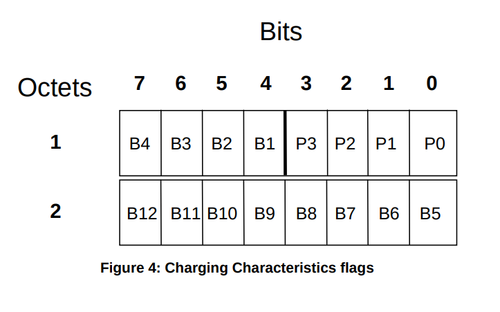
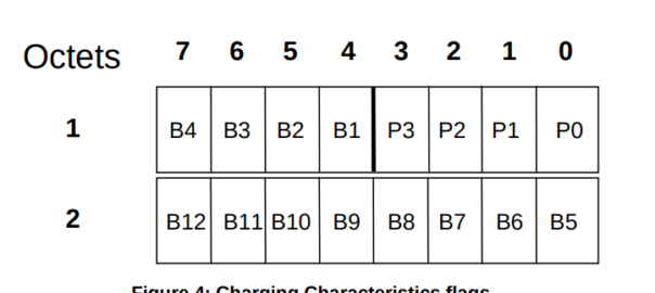
Charging Characteristics consists of a string of 16 bits designated as Profile (P) and Behaviour (B), shown in Figure 4.
The first four bits (P) shall be used to select different charging trigger profiles, where each profile consists of the
following trigger sets:
- S-CDR: activate/deactivate CDRs, time limit, volume limit, maximum number of charging conditions, tariff
times;- G-CDR: same as SGSN, plus maximum number of SGSN changes;
- M-CDR: activate/deactivate CDRs, time limit, and maximum number of mobility changes;
- SMS-MO-CDR: activate/deactivate CDRs;
- SMS-MT-CDR: active/deactivate CDRs.
The Charging Characteristics field allows the operator to apply different kind of charging methods in the CDRs.
A subscriber may have Charging Characteristics assigned to his subscription. These characteristics can be supplied by the HLR to the SGSN as part of the subscription information, and, upon activation of a PDP context, the SGSN forwards the charging characteristics to the GGSN on the Gn / Gp reference point according to the rules specified in Annex A of TS 32.251 [11].
This information can be used by the GSNs to activate CDR generation and control the
closure of the CDR or the traffic volume containers (see clause 5.1.2.2.23) and is included in CDRs transmitted to nodes handling the CDRs via the Ga reference point. It can also be used in nodes handling the CDRs (e.g., the CGF or the billing system) to influence the CDR processing priority and routing.
These functions are accomplished by specifying the charging characteristics as sets of charging profiles and the expected behaviour associated with each profile.
The interpretations of the profiles and their associated behaviours can be different for each PLMN operator and are not subject to standardisation. In the present document only the charging characteristic formats and selection modes are specified.
The functional requirements for the Charging Characteristics as well as the profile and behaviour bits are further defined in normative Annex A of TS 32.251 [11], including the definitions of the trigger profiles associated with each CDR type.
The format of charging characteristics field is depicted in Figure 4. Px (x =0..3) refers to the Charging Characteristics Profile index. Bits classified with a “B” may be used by the operator for non-standardised behaviour (see Annex A of TS 32.251 [11]).
Right, well hopefully next time someone goes looking for this info you’ll find it a bit more easily than I did!