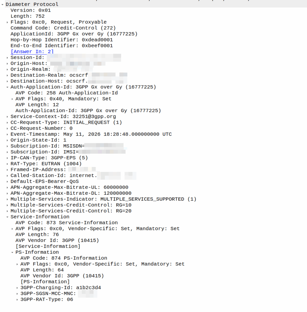
I was recently asked by a potential customer if we supported Gx over Gy.
I’d never heard of this before, so I gave my standard “If it’s in the spec we should support it, but I’ll check” answer, and got them to send me a PCAP, which I’ve got.
This is weird.
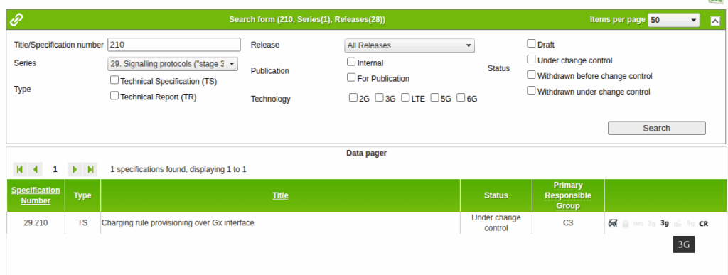
So for starers, Protocoldex has nothing for this application ID (16777225), even though it has all the LTE diameter specs.
The last version was from 2006, in 3GPP release 6, which is two years before LTE was standardized in Release 8. The word LTE does not appear in the doc or in the metadata tags.
It speaks of TPF (Traffic Plane Function) and TPF (Charging Rules Function).
LTE is “Long Term Evolution” – In later releases this draft TPF would evolve into the PGW (before the PGW-C / PGW-U divorce) and the TPF would go on to become the PCRF (and save spring break).
Reading through these early specs is like looking at Homo Eructs (get your mind out of the gutter) and knowing it evolves into Homo Sapiens.
So what does Gx over Gy do? Well, the concept is pretty straightforward, rather than needing a Sy interface between the PCRF and OCS, you can provision policy rules from the OCS, rather than on the PCRF.
So what network functions should implement this standard? Well, the P-GW specs do not reference this as something that’s included in the P-GW, nor is it in the GGSN – This was a “gooch” spec between the hypothetical standards land and real world implementations.
So will we be implementing it? Probably not. But an interesting bit of archaeology and a look through the genealogy of 3GPP.
We support a network in Alaska, and one of the guys we work with there – John – has a story (which I’ll steal here) where he gets a phone call late at night from someone saying they’re in the US Air Force, and uh, they’ve, uh, lost a plane. And since John works for the phone company, he wouldn’t have any idea where it is would you? They ask him.
As a matter of fact, John could see the last cell the SIM the pilot was carrying was attached to, they sent a helicopter out and found the pilot, who survived.
This was a long time ago, and he was able to pin the location down to a cell (sector), and lookup which direction the sectors were pointing for that cell and the location of it, to give a pretty good idea of the general search area.
Now that everyone carries a GPS in their pockets, the level of accuracy here is a lot more than just which cell are you served by (although that’s a lot of accuracy anyway, and not to be ignored).
There’s significant privacy implications here and a lot of misinformation about pinging cell towers and “zoom enhance” stuff.
I figured I’d actually share how this works IRL – There’s nothing ‘secret‘ here – All of this stuff is in the 3GPP standards which outline how mobile networks should behave.
There’s roughly 4 levels of accuracy in cell phone networks, we’ll cover each one, and how the network treats it.
(I’m talking 4G/5G here as most of the world has moved on or is already moving on from 2G/3G)
Tracking Area Level Accuracy
Cell sites get grouped into tracking areas, they’re kinda like broadcast domains in TCP/IP networking, when you need to “page” (find) a phone that’s “idle” (sleeping) you page the tracking area.
Tracking Area sizing has sweet spots, you want more than a few cells, commonly about a dozen or so in the same geographic area get lumped into the same tracking area. In regional areas you might have a large geographic area – Up to a few hundred Km in regional Australia for example, lumped into a single tracking area, whereas in a city that might be a single city block.
If you move between cells inside the same tracking area, then your phone doesn’t need to say to the network “hey I’m moving cells” – It’s only if we go over to a new tracking area that the phone needs to wake up and tell the network it’s now in this new tracking area.
(If you’ve got a tracking area that’s too big (too many cells) then it becomes a nightmare to find who you’re looking for, as the paging channels are always blaring out IDs, tracking areas too small and you’ve got phones having to constantly say “hey I’m moving to this tracking area now” – If you want to learn more about Tracking Areas I’ve written about them on the blog before)
The core network (MME/AMF) always knows the location of a phone at minimum to the tracking area – It’s the base level of location the network has to work with.
Cell ID Level Accuracy (CGI / E-CGI)
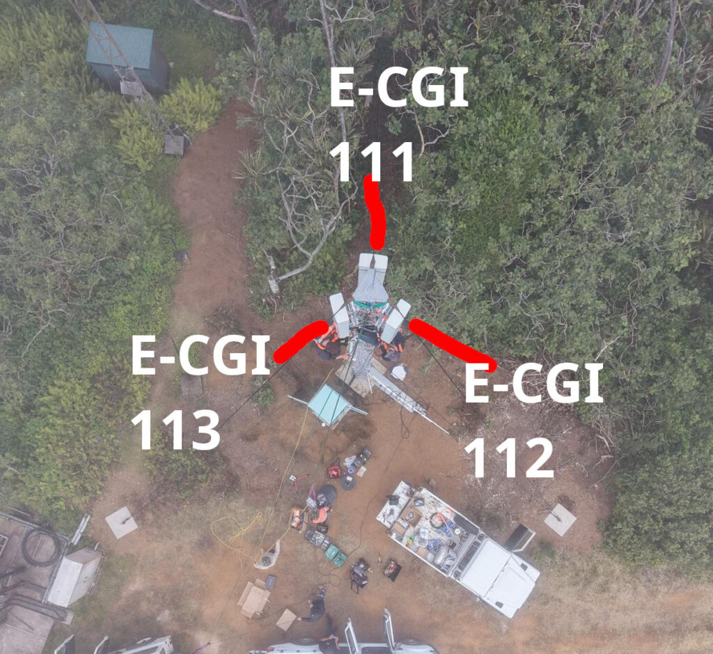
Every cell site sector (cell) has a unique ID to denote which carrier you’re connected to. If you’ve got a 3 sector site, with a single layer per cell sector, then that’s 3 Cell Global Identifiers (CGIs) – one for each sector.
Here’s a tower we put up recently, the CGIs I’ve drawn on are just examples, but if you’re connected to the sector facing North, you’d have CGI of 111, if you’re connected to the cell to the south east, you’d have 112, and the one to the south west would be 113.
CGIs are just numbers, they could be any number, all that matters is that number is unique (ish) in the network, they don’t need to be sequential, or have any common digits.
If we know the CGI of a given user we can kinda draw a 1/3rd wedge off the side of the tower in the direction the antenna is pointing, and if you’re inside that wedge, and that tower is still providing coverage, then we know the customer is somewhere inside that wedge.
But those wedges can still be large, so the margin of error for locating someone is still pretty large. You can probably answer the question of “Are they in the office or are they at home” if they’re in different suburbs.
When the network wants to know a bit more about where the phone is located, it can ask the cell site which Global Cell ID the phone is in, this is pretty rare, but can be done. When the phone is actively doing stuff, like making a call, using data or sending a text, the network knows the CGI of the event.
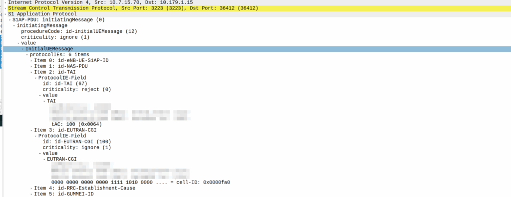
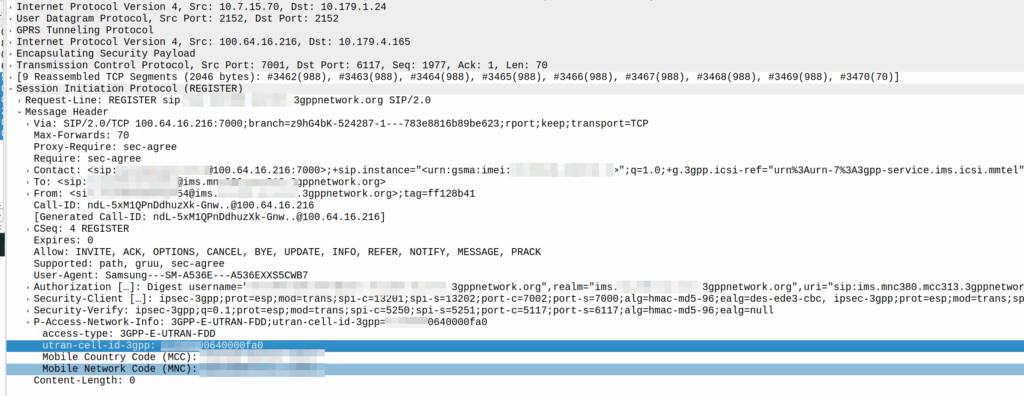
My lab is setup with CGI 4000 and TAC 100, and this information is littered across every signaling message.
Initial Attach message
Note: The encoding shows up as 0000 0000 0000 0000 1111 1010 0000 …. = cell-ID: 0x0000fa0 for CGI 4000, just roll with it, the spec explains why this is.
A SIP REGISTER message from my lab, showing the CGI (00640000fa0)
GNSS LPP Positioning
When the Cell ID level is not accurate enough, the network can request the phone to provide it’s location, using whatever it’s got available to it.
In reality, this is either done by an engineer from the phone company with the permissions to do so, or directly by law enforcement using the SLh/SLg Diameter interfaces.
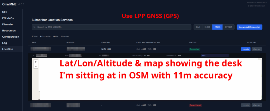
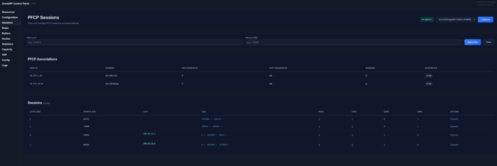
When an engineer does it, there’s usually a portal they can go to, like this one in OmniMME, they search the IMSI or MSISDN, and then can get the location information via a variety of methods.
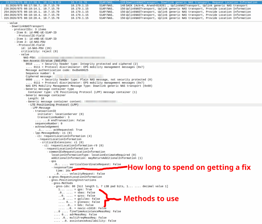
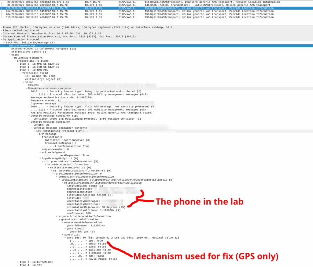
Your phone gets a message from the network, that says “Hey phone, tell me where you are”.
If you’ve got enough access to the baseband you can even block these requests should you feel so inclined.
I’ve included some Wireshark captures of how this actually looks and how it looks from the Web UI of the MME, with the address removed.
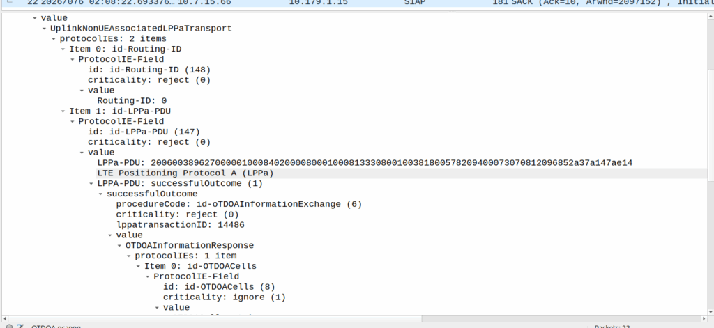
OTDOA – “Pinging”
Sometimes you don’t get an indoor location with GPS or the phone might be too old to support LPP Positioning, no GPS built in or something.
In those scenarios, we use “Time Difference of Arrival” to calculate the position by measuring time between 2 or more cell sites, and calculating the time between when a signal was sent to a phone, and when it receives it, to calculate distance from the base station.
This is better than CGI as it gives you an idea of how far from the cell site the phone is, and the cell site, but it doesn’t return a map with “you are here”, but rather some rough distances, and CGIs for each cell it can see.
The engineer then pulls up a map of all the cell sites, finds the CGIs the cell phone can see, headings for each CGI and tries to do some early high school maths like someones life actually depends on it.
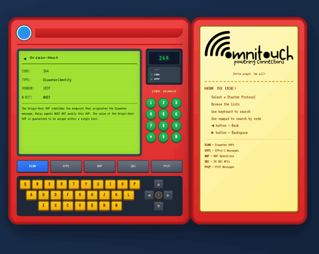
I do a lot of protocol testing, writing Diameter/PFCP/GTP-C etc, and spend a lot of time referencing the standards.
So I built this – Inspired by a 1990s video game / TV / Playing card franchise online reference tool, but rather than identifying pocket monsters, it’s identifying AVPs and stuff
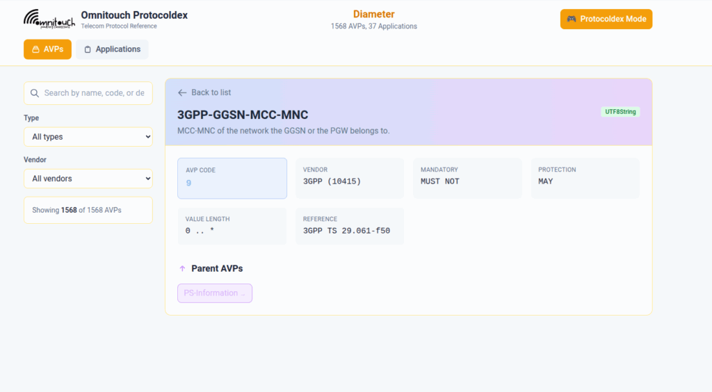
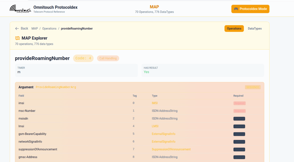
You can punch in the AVP code, AVP name, description, etc, for Diameter, PFCP, GTP-C, MAP or SBI and see all the details to go with it.
I’ve been using it a heap, hopefully some of you might find it useful:
When a UE enters Idle mode, the network releases radio resources and the UE enters power saving mode.
When the UE wants to send data (Uplink) the UE just tells the network “hey I want to send something” and away it goes, nice and simple.
But when the network wants to send data to the UE (Downlink) then the UPF needs a method to tell the Control Plane (SGW-C or SMF) that there’s data waiting and to go and page the UE.
A prime example of this is when you’ve got a Mobile Terminated VoLTE call coming in, you need a way to tell the UE to wake up out of Idle mode because you’ve got something to send to it (a SIP INVITE).
But in order for this to work, we can’t just say “Hey I’ve got some packets for you” and let them get dropped, the UPF also needs to buffer (store temporarily) the downlink packets for the UE until the UE comes out of Idle mode, and then flush them out to deliver them to the UE.
So let’s look at the flow.
Enabling Buffering (Idle Mode)
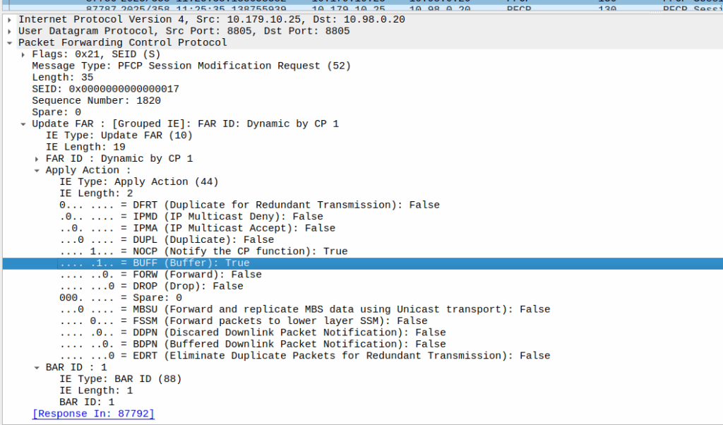
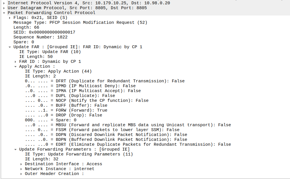
When the sub enters idle mode, the Control Plane (SGW-C for an EPC or SMF for a 5GC) it sends a Session Modification Request but with the BUFF (Buffer) and NOCP (Notify Control Plane) flags set, and FORW (Forward) turned off.
What this means is now for packets to that bearer, the UPF must:
Not forward any traffic
Buffer the traffic
Notify the control plane when the first packet comes in that we buffer
Then the UPF just sits and waits for any incoming packets.
The Notify
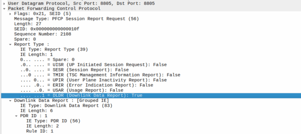
When the UE gets an incoming packet that it’s supposed to buffer and notify, well, it does just that.
The packets are copied into a buffer, in sequence, and for the first packet, the UPF must send a notification to the Control Plane.
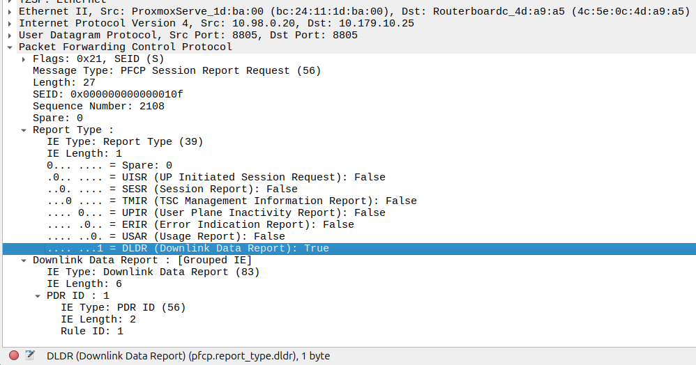
That looks like this, it’s just a Session Report Request with the Dowlink Data Report flag.
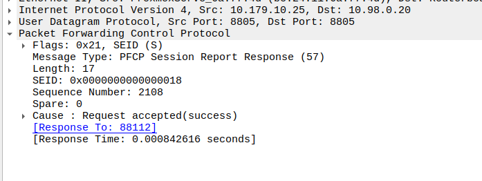
Now the SMF/SGW-U sends back a Session Report Response and starts the process of paging the UE.
At the same time the UPF keeps buffering – It’s work is not done.
Flushing and Forwarding
Once the UE has become reachable, the Control Panel needs to modify the bearer to turn back on forwarding. It does through another Session Modification Request, this is the inverse of the one it sent to turn on buffering, as we’re turning off buffering and notifications, and turning on forwarding.
Now the UPF flushes it’s buffer – It’ll send all the packets that were queued up out over the wire towards the gNB / eNodeB, so the SIP INVITE for the MT call or whatever will make it through.
One thing to note is that the packets that get buffered are going to take some time to get delivered, as the NOTIFY / page UE / reconnect UE / Session Modification Request (to enable forwarding again) needs to happen before the buffers are flushed and delivered.
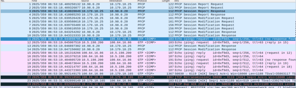
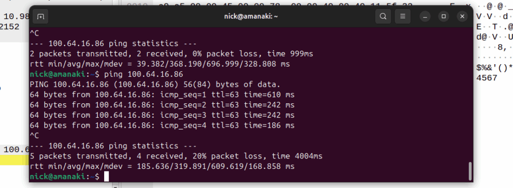
Notice the latency spike on the first packet? 610ms? That’s because the UE had to be paged to wake up.
And that’s pretty much it, the UPF has now flushed it’s buffers and moves back to forwarding actions.
Our team recently shipped a new UPF which is a huge improvement on our old UPF, and I drew the short straw of doing all the interop testing for the IMS.
Initially I thought there was an issue with IP routing, as I’d never see the SIP register from the UE, but I would see the IMS APN coming up.
I could access the internet from the UE IPs just fine, but that’s going to public IPs, whereas the P-CSCF is in private address space, and hosted on the same box as the UPF.
I spent hours on this as my lab servers do routing on a stick, and I thought some hardware offload somewhere was trying to fast path my packets and send them back to the server without going via the router.
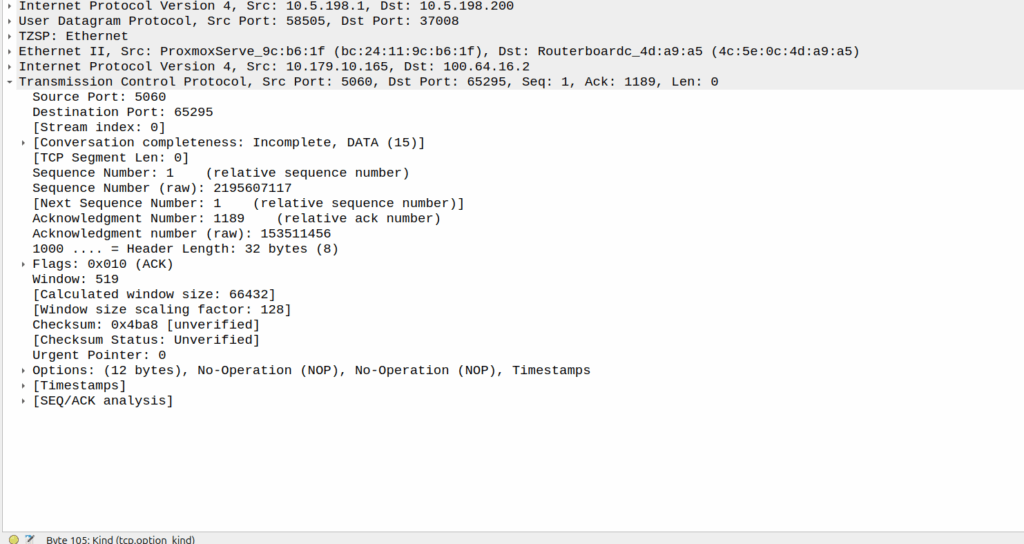
Then I dug a little deeper and found I could see the 3 way handhake between the UE an the P-CSCF, but no SIP packets.
Successful 3 way handshake between the UE and the P-CSCF on TCP 5060
This was confusing, clearly we had at least intermittent two way comms – the 3 way TCP handshake confirmed that, but then why were packets not getting across?
We have an XCAP server hosted on our P-CSCF instances, so I tried hitting that from the phone in case there was something weird about routing to the network segment that hosts the P-CSCF, but I could hit the XCAP server just fine, so now I was certain the UE IP pool could route to the P-CSCF and 3 way handshake for TCP was working and payload could be pushed.
Clearly we can route to the P-CSCF as that’s where this XCAP server is hosted
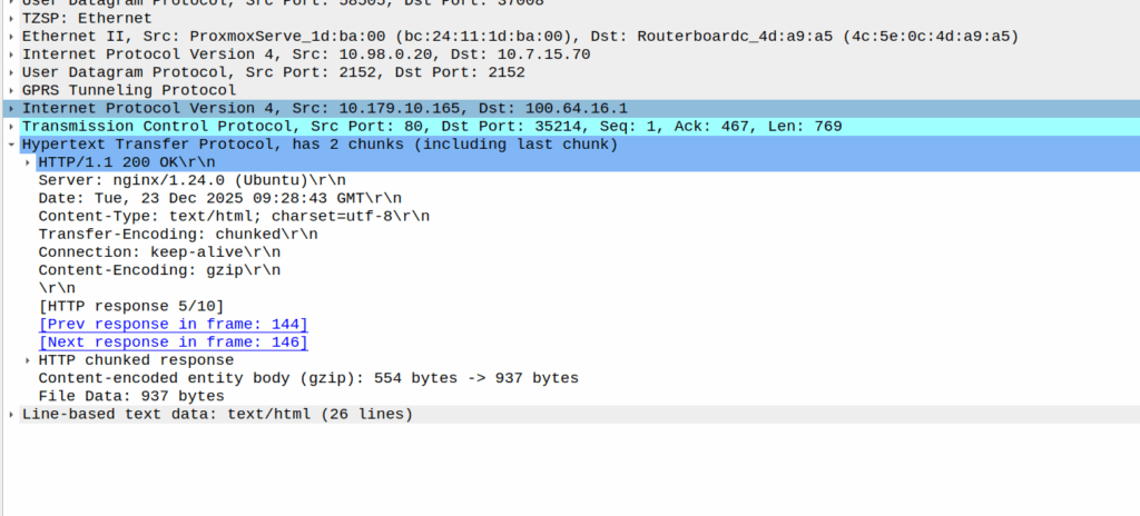
Then I dug into what happened after the 3 way handshake, and I found a TCP payload containing the start of the SIP REGISTER.
Hmm, we have a SIP Fragment here at least…
I traced it all the way through and lo, it’s hitting the P-CSCF:
And the fragment is recieved on the P-CSCF
Okay, but then what happens, because it’s only a fragment, not the complete re-assembled packet, so what’s going on?
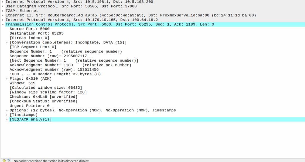
Well, the P-CSCF sends a TCP ACK back to the UE.
And the TCP fragment containing the first part of the REGISTER gets an ACK back from the P-CSCF
The ACK gets forwarded to the UPF:
And that TCP ack makes it to the P-CSCF
And then… Nothing? The UPF never encaps the TCP ACK back into GTP-U and never sends it onto base station.
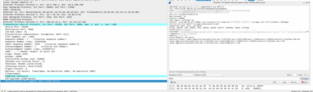
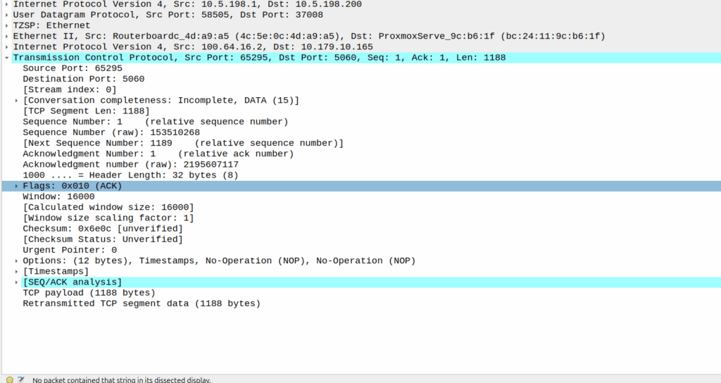
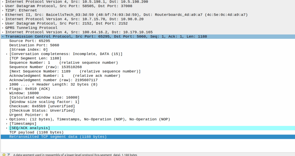
Eventually the UE re-sends the payload with the start of the REGISTER, but it does not get the ACK from the P-CSCF.
Retransmitted TCP segment containing the REGISTER from the UE
So naughty UPF right? Not forwarding that ACK for some reason?
I started digging, maybe the ACK was getting routed weirdly and landing on the UPF without going through the router?
Well not quite…
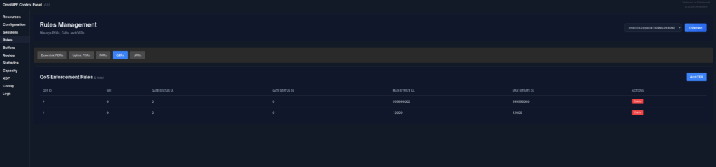
When I started digging into the QER rules being installed I noticed the MBR bitrate we had on the IMS APN in the HSS was tiny.
The UPF can only gate on traffic to the UE, so was gating the ACK traffic, as the QER had consumed all the bandwidth so the ACK never made it back.
Time wasted – About 4 hours, but I will not make this mistake again!
We were testing international roaming for a customer, roaming into the US where one of our team members (shoutout to Cody) is based.
So we sent Cody some SIMs and asked them to run the basic tests for us, but no IMS APN would attach.
We’d get them to power up the phone, fire up a trace on the roaming PGWs, but never seeing an attempt to attach on the IMS APN (No Create Session Request from the SGW in the vPMN).
The operator we were roaming into swore their side was correct – that IMSI was allowed for the IMS APN for testing, but whenever we’d run a trace, same thing, default bearer just fine but no CSR for the IMS APN, as if the IMS APN was blocked on the roaming network (Which is common on networks where you haven’t launched VoLTE but do have data roaming).
The steps we would do is:
Person in the US turns on phone tries to attach
I fire up my computer, get a trace running
Person in the US airplanes the device
I monitor for CSRs on the PGWs for that IMSI
But no CSR for the IMS APN would ever come through.
After a few attempts, here’s what we found was happening:
The phone would get powered up
The phone would roam onto the vPMN in the US and the default bearer would come up
The phone would try to attach to the ims APN, this would work for this SIM which was whitelisted, and the Create Session Request for the ims APN went to the PGW in the hPMN
The ims APN came up as expected
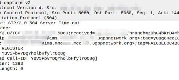
The phone would send a SIP REGISTER (So far so good)
Our IMS had an issue with Rx routing in this scenario, so the SIP REGISTER would timeout, and when it timed out, a 504 error was sent back to the phone by the P-CSCF and it set the Retry-After header to 3600 seconds.
The phone would not try again for as long as that timer value was set.
At this point we’d start a trace, airplane the device, and see no IMS APN attach attempt.
This 504 Timeout would all happen when the phone fired up before we had any traces running, so we weren’t capturing that.
I’d wrongly assumed that airplaning the device after starting a trace would reset the state fully, but it doesn’t, neither does a restart of the phone.
When we’d started a trace and airplane the phone, the phone wouldn’t try to attach to the ims APN as it was still inside the Retry-After time window from when we’d first fired it up.
Per RFC 3261, the phone should not try again during this time, which in our case meant no attempt to attach to the IMS APN, this makes sense – it protects the network against the thundering herd problem, but made this otherwise simple fault really hard to find.
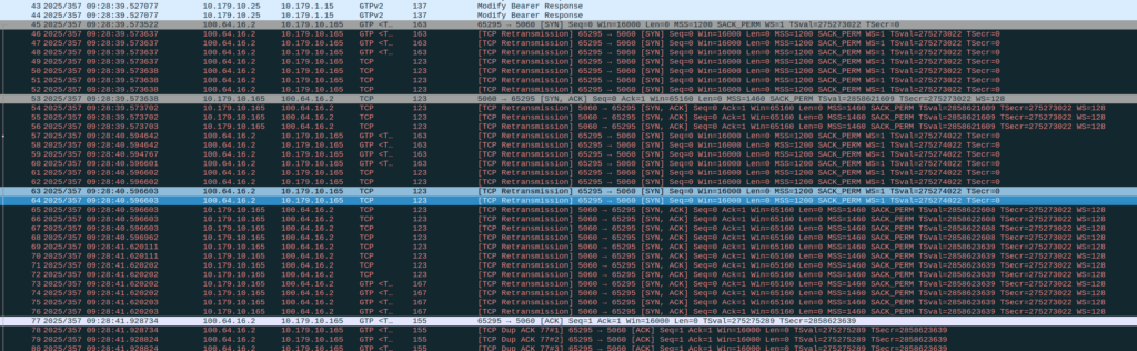
So we’ve found this scenario that occurs on some Samsung UEs, in certain radio contions, where midway through an otherwise normal voice call, the UE sends “mystery” data (Not IP data), which in turn causes the UPF to send the error indication and drop the bearer, which in turn drops the call.
The call starts, like any normal call, SIP REGISTER, INVITE, etc.
The P-CSCF / PCRF / PGW set up the dedicated bearer for the voice traffic, and the RTP stream starts flowing over it.
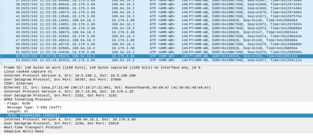
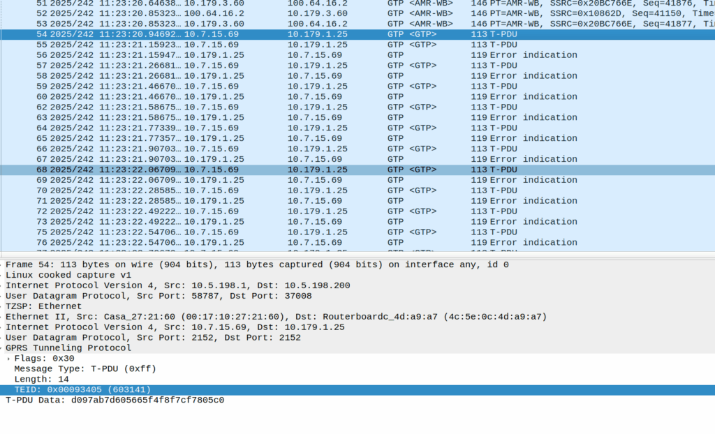
Then the UE sends these weird packets instead of the RTP stream:
These are GTP-U encapsulated data, with the TEID that matches the TEID used for the RTP stream, but there’s no IP data in them – they’re only 14 bytes long and sent by the UE.
Here’s some examples of what’s sent (each line is a packet):
An IPv4 header is 20 bytes long, and IPv6 header is 40, so this is too short for either of those protocols, but what else could it be?
There’s some commonality of course, starts d0 as the first octet, then d1, d2, d3, etc. So that’s something?
I thought perhaps it was a boundary issue, that the standard RTP packet was being split across multiple GTP-U payloads, but that doesn’t appear to be the case.
An Ethernet header is 14 bytes, but if we were to decode this as Ethernet there’s still nothing it’s transporting, and the destination MAC is changing sequentailly if that’s the case, which would be even weirder.
I also thought about RTP that for some reason has lost it’s IP/UDP header, as the sequentially counting byte at the start could be the RTP sequence number, but that’d be 19 bytes minimum and the sequence number is the 3rd and 4th byte, not the first.
Whatever they contain, we see this sent over and over for a few seconds, then bam, back to normal RTP stream flowing.
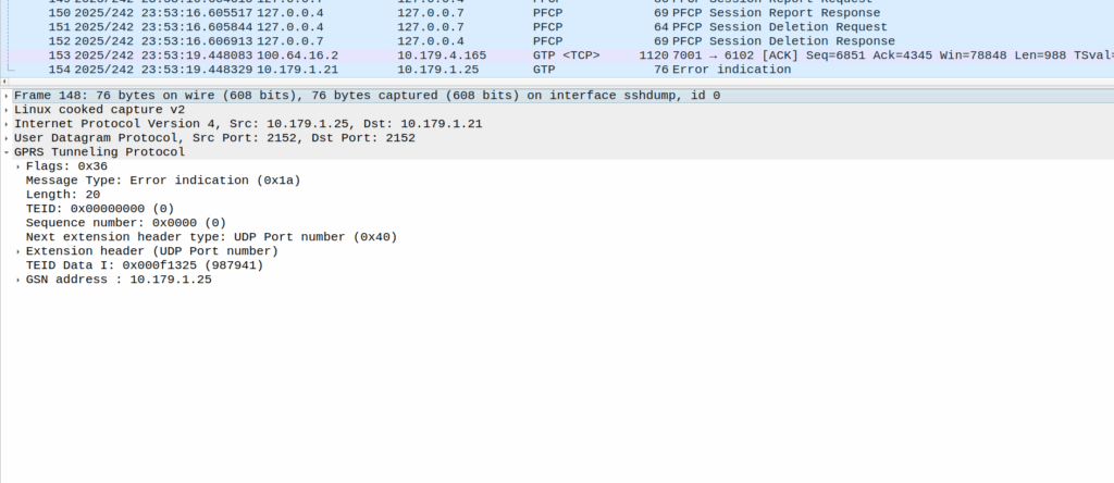
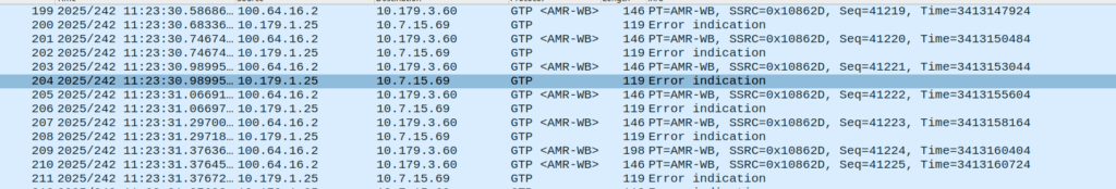
Or at least it should be, but the invalid packet causes the UPF to generate a GTP-U Error Indication.
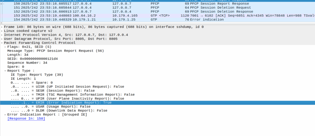
These Error Indication payloads eventually lead to the next PFCP Session Report Request having the Error Indication Report (ERIR) flag set to True.
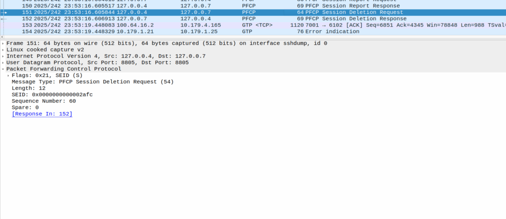
When the PGW-U gets this, it sends a Session Delete Request, which dutifully drops the bearer.
Meaning the session drops on the EPC side, and the RTP drops with it, eventually a BYE is sent from the phone due to RTP timeout.
The above screenshot shows a different cause of GTP-U Error Indication – At this point the bearer has been dropped on the EPC side and these are Error Indications to report it doesn’t know the TIED / bearer.
How to fix this?
Well, unlikely we’ll get a fix on the Samsung side, so we’ll need to not drop the bearer on the PGW-C if we get a lot of Error Indications, and hope for the best.
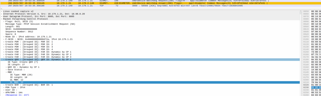
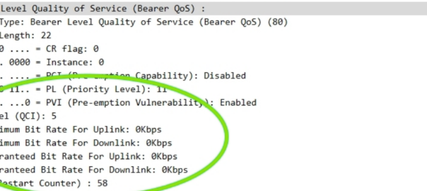
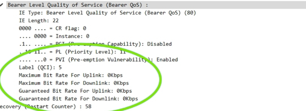
The other day I had a query about a roaming network that was sending Bearer Level QoS parameters in the Create Session Request to 0Kbps, up and down rather than populating the MBR values.
I knew for Guaranteed Bit Rate bearers that this was of course set, but for non GBR bearers (QCI 5 to 9) I figured this would be set the to MBR, but that’s not the case.
So what gives?
Well, according to TS 29.274:
For non-GBR bearers, both the UL/DL MBR and GBR should be set to zero.
So there you have it, if it’s not a QCI 1-4 bearer then these values are always 0.
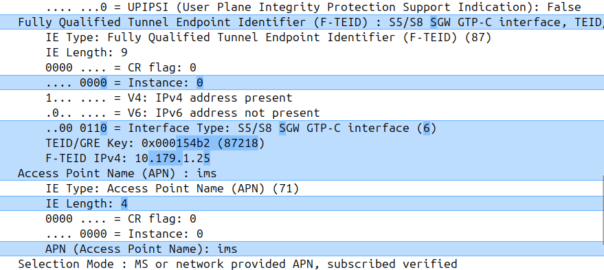
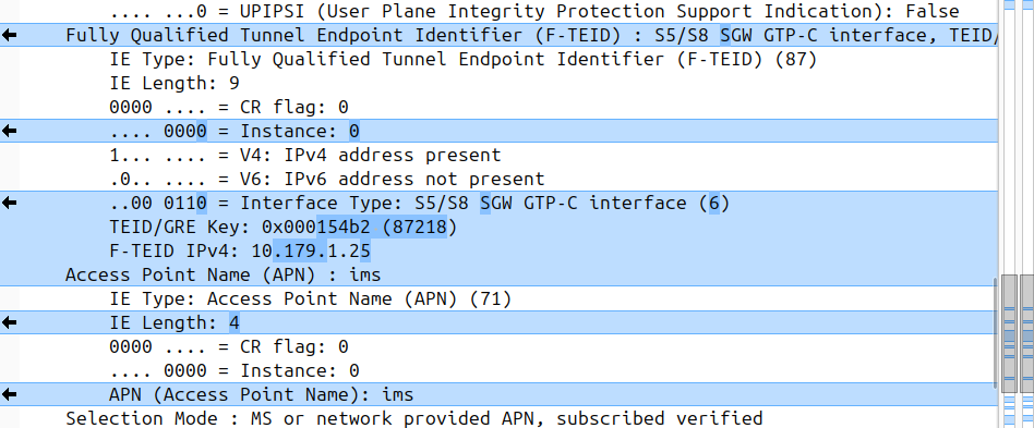
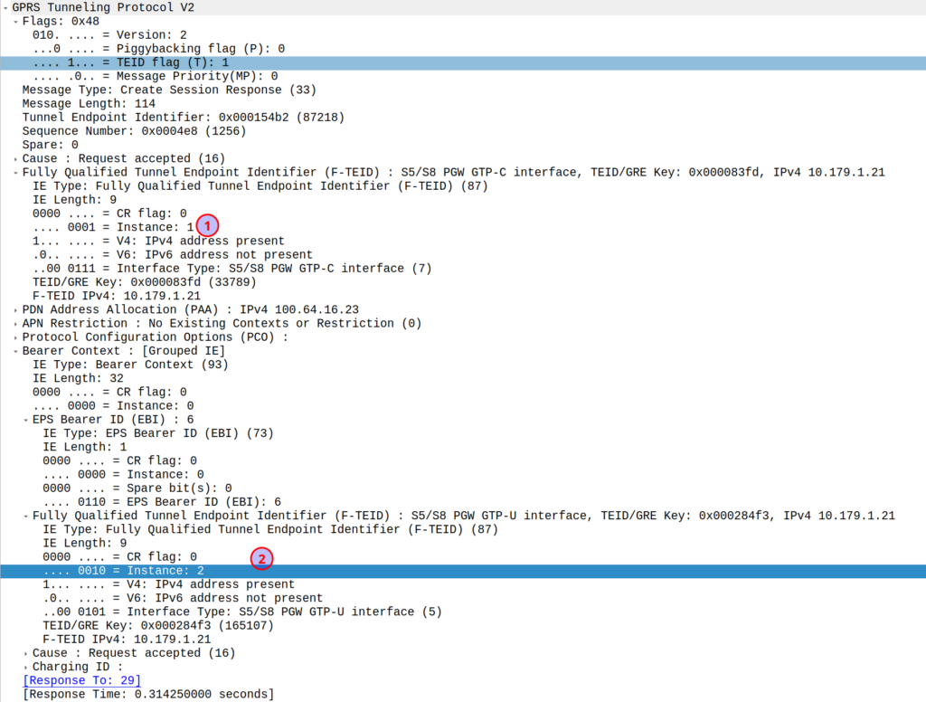
I was diffing two PCAPs the other day trying to work out what’s up, and noticed the Instance ID on a GTPv2 IE was different between the working and failing examples.
If more than one grouped information elements of the same type, but for a different purpose are sent with a message,
these IEs shall have different Instance values.
So if we’ve got two IEs of the same IE type (As we often do; F-TEIDs with IE Type 87 may have multiple instances in the same message each with different F-TEID interface types), then we differentiate between them by Instance ID.
The only exception to this rule is where we’ve got the same data, so if you’ve got one IE with the exact same values and purpose that exists twice inside the message.
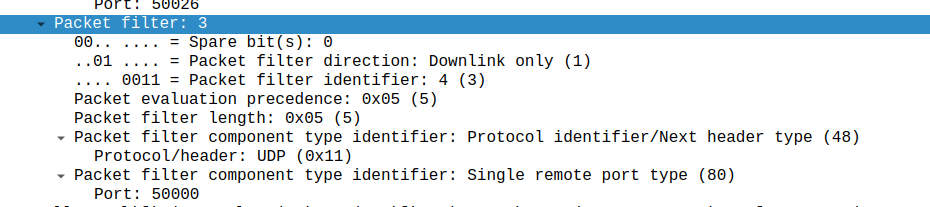
What is included in the Charging Rule on Gx ultimately turns into a Create Bearer Request on GTPv2-C.
But the mapping it’s always obvious, today I got stuck on the difference between a Single remote port type, and a single local port type, thinking that the Packet Filter Direction in the TFT controlled this – It doesn’t – It’s controlled by the order of your Traffic Flow Template rule.
Input TFT:
"permit out 17 from any 50000 to any"
Leads to Packet filter component type identifier: Single remote port type
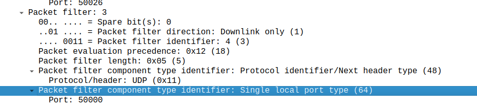
Whereas a TFT of:
permit out 17 from any to any 50000
Leads to Packet filter component type identifier: Single local port type (64)
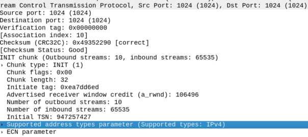
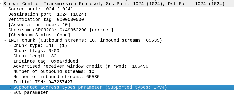
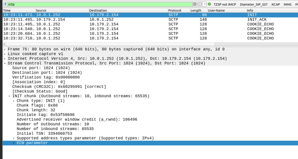
The other side of the SCTP connection didn’t like my SCTP parameters.
My SCTP INIT looked like this:
By default, Linux includes support for the ECN and SupportedAddressTypes parameters in the SCTP INIT.
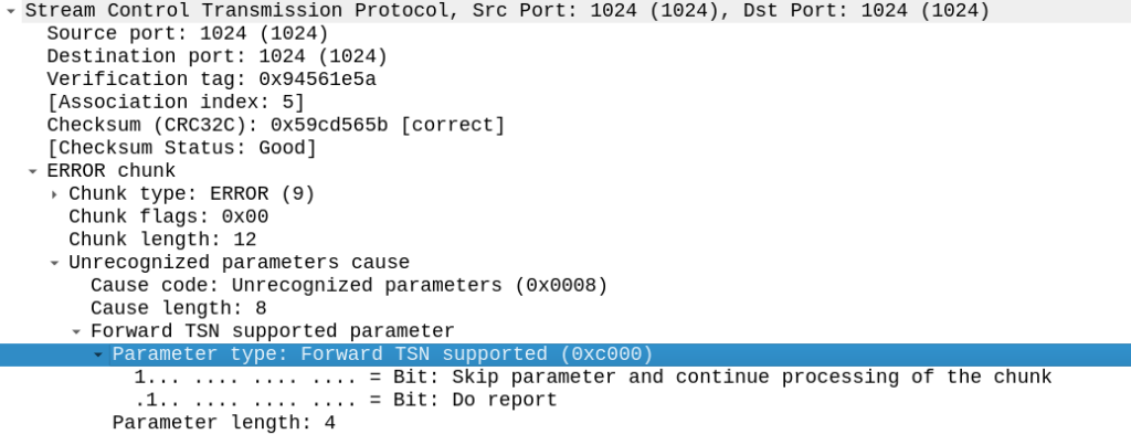
But the other side did not like this, it sent back an ERROR stating that:
Okay, apparently it doesn’t like the fact that we support Forward Transmission Sequence Numbers – So how to turn it off?
I’m using P1Sec’s PySCTP library to interact with the SCTP stack, and I couldn’t find any referneces to this in the code, but then I rememberd that PySCTP is just a wrapper for libsctp so I should be able to control it from there.
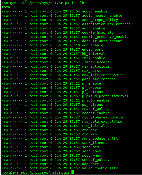
Inside /proc/sys/net/sctp we can see all the parameters we can control.
To disable the Forward TSN I need to disable the feature that controls it – Forward Transmission Sequence numbers are introduced in the Partial Reliability Extension (RFC 3758). So it was just a matter of disabling that with:
S8 Home Routing is a really simple concept, the traffic goes from the SGW in the visited PLMN to the PGW in the home PLMN, so the PCRF, OCS/OFCS, IMS, IP Addresses, etc, etc, are all in the home network, and this avoids huge amounts of complexity.
But in order for this to work, the visited network MME needs to find the PGW of the home network, and with over 700 roaming networks in commercial use, each one with potentially hundreds of unique APNs each routing to a different PGW, this is a tricky proposition.
If you’ve configured your PGW peers statically on your MME, that’s fine, but it doesn’t scale very well – And if you add an MVNO who wants their own PGW for serving their APN, well you’ll be adding some complexity there to, so what to do?
Well, the answer is DNS.
By taking the APN to be served, the home PLMN and the interface type desired, with some funky DNS queries, our MME can determine which PGW should be selected for a request.
Let’s take a look, for a UE from MNC XXX MCC YYY roaming into our network, trying to access the “IMS” APN.
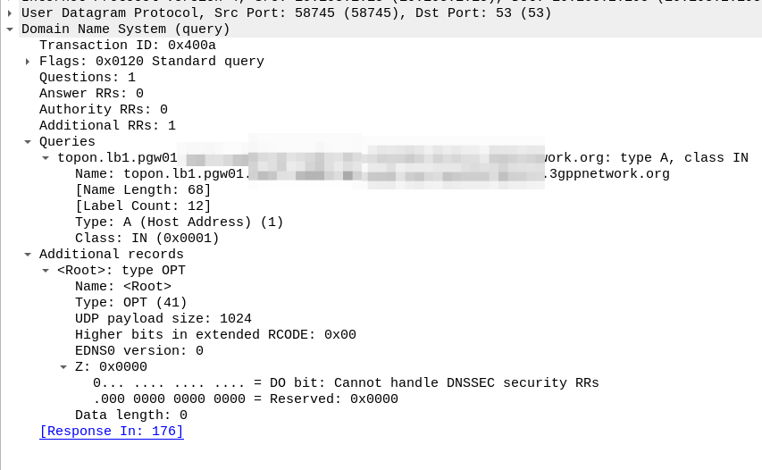
Our MME knows the network code of the roaming subscriber from the IMSI is MNC XXX, MCC YYY, and that the UE is requesting the IMS APN.
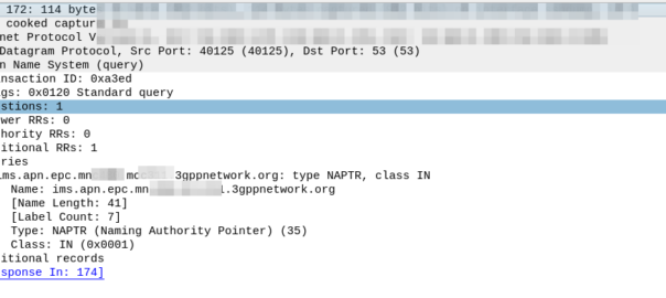
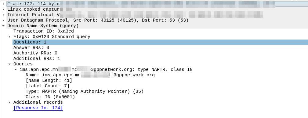
So our MME crafts a DNS request for the NAPTR query for ims.apn.epc.mncXXX.mccYYY.3gppnetwork.org:
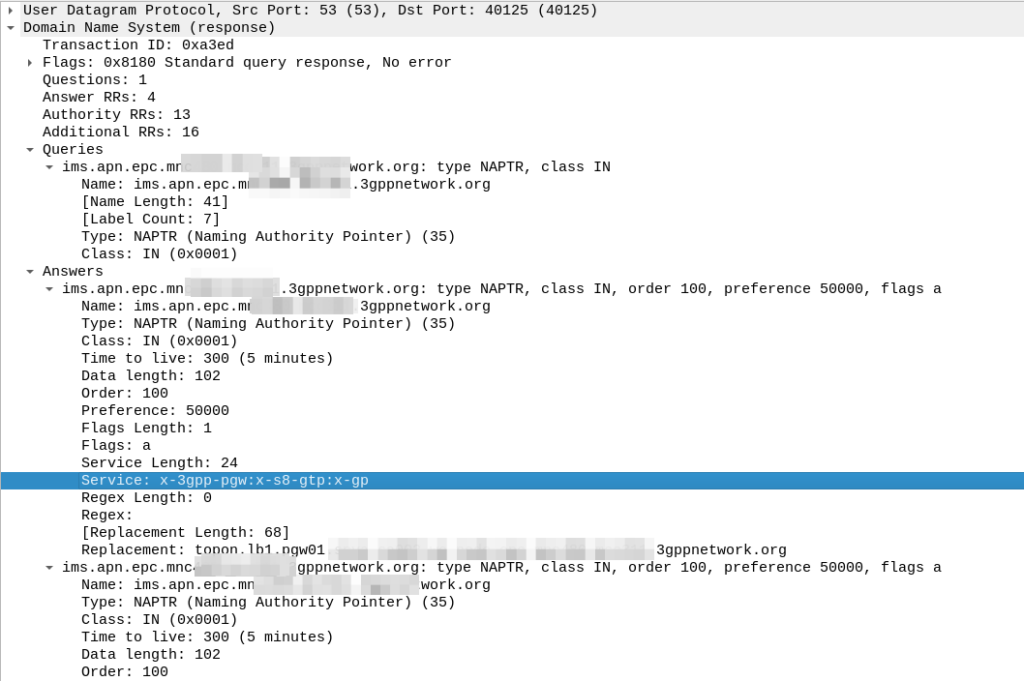
Because the domain is epc.mncXXX.mccYYY.3gppnetwork.org it’s routed to the authoritative DNS server in the home network, which sends back the response:
We’ve got a few peers to pick from, so we need to filter this list of Answers to only those that are relevant to us.
First we filter by the Service tag, whihc for each listed peer shows what services that peer supports.
But since we’re looking for S8, we need to find a peer who’s “Service” tag string contains:
x-3gpp-pgw:x-s8-gtp
We’re looking for two bits of info here, the presence of x-3gpp-pgw in the Service to indicate that this peer is a PGW and x-s8-gtp to indicate that this peer supports the S8 interface.
A service string like this:
x-3gpp-pgw:x-s5-gtp
Would be excluded as it only supports S5 not S8 (Even though they are largely the same interface, S8 is used in roaming).
It’s also not uncommon to see both services indicated as supported, in which case that peer could be selected too:
x-3gpp-pgw:x-s5-gtp:x-s8-gtp
(The answers in the screenshot include :x-gp which means the PGWs advertised are also co-located with a GGSN)
So with our answers whittled down to only those that meet our needs, we next use the Order and the Preference to pick our best candidate, this is the same as regular DNS selection logic.
From our candidate, we’ve also got the Regex Replacement, which allows our original DNS request to be re-written, which allows us to point at a single peer.
In our answer, we see the original request ims.apn.epc.mncXXX.mccYYY.3gppnetwork.org is to be re-written to topon.lb1.pgw01.epc.mncXXX.mccYYY.3gppnetwork.org.
This is the FQDN of the PGW we should use.
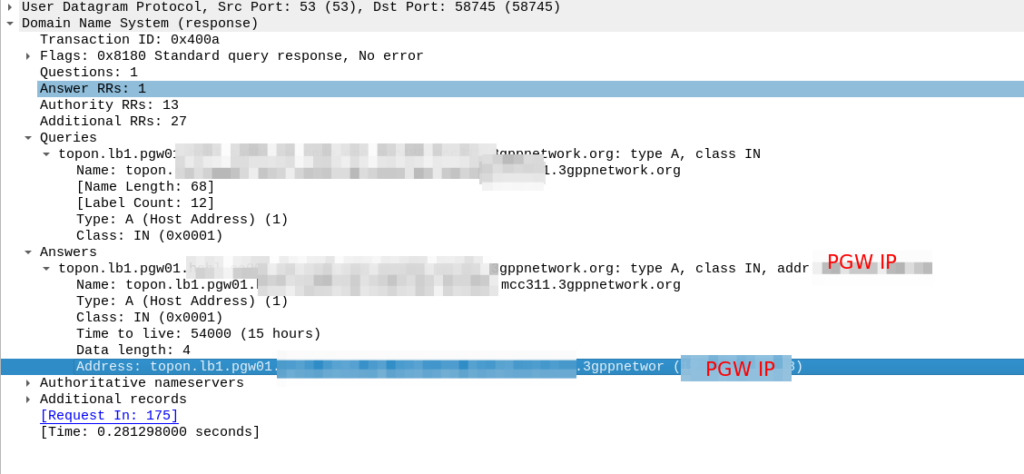
Now we know the FQND we should use, we just do an A-Record lookup (Or AAAA record lookup if it is IPv6) for that peer we are targeting, to turn that FQDN into an IP address we can use.
And then in comes the response:
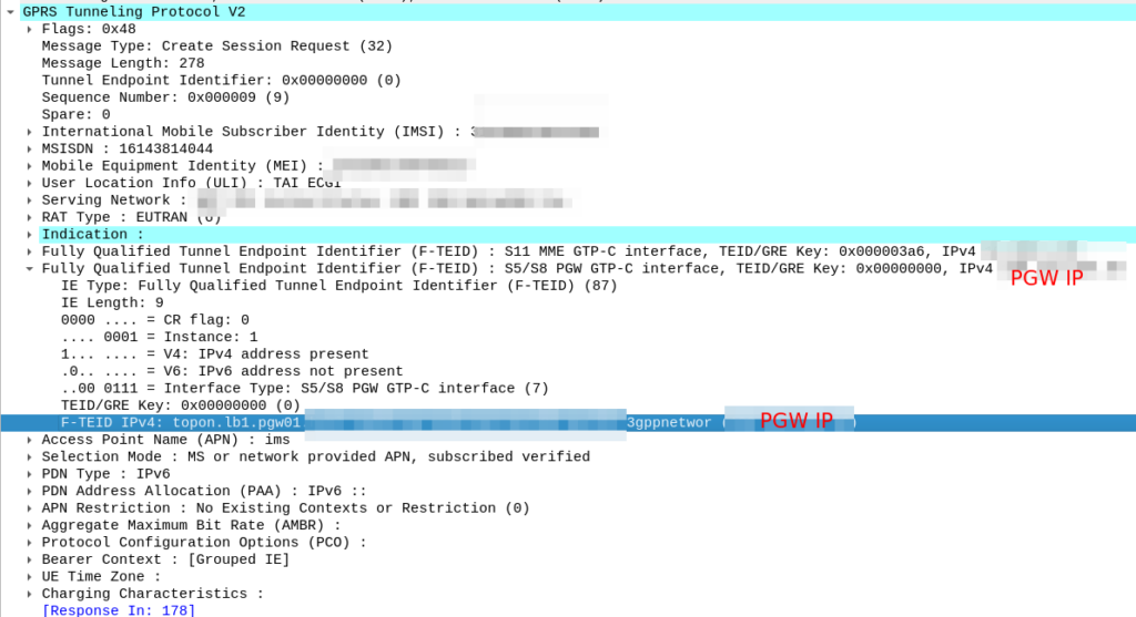
So now our MME knows the IP of the PGW, it can craft a Create Session request where the F-TEID for the S8 interface has the PGW IP set on it that we selected.
For more info on this TS 129.303 (Domain Name System Procedures) is the definitive doc, but the GSMA’s IR.88 “LTE and EPC Roaming Guidelines” provides a handy reference.
How does one encode / interpret the value of this AVP / IE was the question I set out to answer.
TS 29.274 says:
For the encoding of this information element see 3GPP TS 32.298
TS 32.298 says:
The functional requirements for the Charging Characteristics as well as the profile and behaviour bits are further defined in normative Annex A of TS 32.251
TS 32.251 Annex A says:
The Charging Characteristics parameter consists of a string of 16 bits designated as Behaviours (B), freely defined by Operators, as shown in TS 32.298 [51]. Each bit corresponds to a specific charging behaviour which is defined on a per operator basis, configured within the PCN and pointed when bit is set to “1” value.
After a few circular references I found this is imported from 32.298.
Finally we find some solid answers hidden away in TS 132 215, under the Charging Characteristics Profile index.
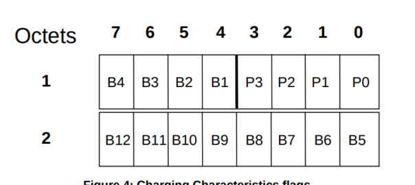
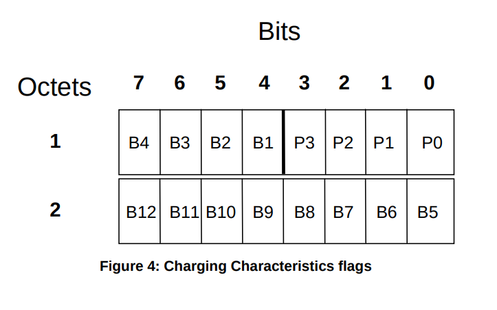
Charging Characteristics consists of a string of 16 bits designated as Profile (P) and Behaviour (B), shown in Figure 4. The first four bits (P) shall be used to select different charging trigger profiles, where each profile consists of the following trigger sets:
S-CDR: activate/deactivate CDRs, time limit, volume limit, maximum number of charging conditions, tariff times;
G-CDR: same as SGSN, plus maximum number of SGSN changes;
M-CDR: activate/deactivate CDRs, time limit, and maximum number of mobility changes;
SMS-MO-CDR: activate/deactivate CDRs;
SMS-MT-CDR: active/deactivate CDRs.
The Charging Characteristics field allows the operator to apply different kind of charging methods in the CDRs. A subscriber may have Charging Characteristics assigned to his subscription. These characteristics can be supplied by the HLR to the SGSN as part of the subscription information, and, upon activation of a PDP context, the SGSN forwards the charging characteristics to the GGSN on the Gn / Gp reference point according to the rules specified in Annex A of TS 32.251 [11].
This information can be used by the GSNs to activate CDR generation and control the closure of the CDR or the traffic volume containers (see clause 5.1.2.2.23) and is included in CDRs transmitted to nodes handling the CDRs via the Ga reference point. It can also be used in nodes handling the CDRs (e.g., the CGF or the billing system) to influence the CDR processing priority and routing.
These functions are accomplished by specifying the charging characteristics as sets of charging profiles and the expected behaviour associated with each profile.
The interpretations of the profiles and their associated behaviours can be different for each PLMN operator and are not subject to standardisation. In the present document only the charging characteristic formats and selection modes are specified.
The functional requirements for the Charging Characteristics as well as the profile and behaviour bits are further defined in normative Annex A of TS 32.251 [11], including the definitions of the trigger profiles associated with each CDR type.
The format of charging characteristics field is depicted in Figure 4. Px (x =0..3) refers to the Charging Characteristics Profile index. Bits classified with a “B” may be used by the operator for non-standardised behaviour (see Annex A of TS 32.251 [11]).
Right, well hopefully next time someone goes looking for this info you’ll find it a bit more easily than I did!
No one spends marketing dollars talking about the problems with a tech and vendors aren’t out there promoting sweating existing assets. But understanding your options as an operator is more important now than ever before.
Sidebar; This post got really long, so I’m splitting it into 3…
We’re often asked to help define a a 5G strategy for operators; while every case is different, there’s a lot of vendors pushing MNOs to move towards 5G standalone or 5G-SA.
I’m always a fan of playing “devil’s advocate“, and with so many articles and press releases singing the praises of standalone 5G/5G-SA, so as a counter in this post, I’ll be making the case against the narratives presented to operators by vendors that the “right” way to do 5G is to introduce 5G Standalone, that they should all be “upgrading” to Standalone 5G.
With Mobile World Congress around the corner, now seems like a good time to put forward the argument against introducing 5G Standalone, rebutting some common claims about 5G Standalone operators will be told. We’ll counterpoint these arguments and I’ll put forward the case for not jumping onto the 5G-SA bandwagon – just yet.
On a personal note, I do like 5G SA, it has some real advantages and some cool features, which are well documented, including on this blog. I’m not looking to beat up on any vendors, marketing hype or events, but just to provide the “other side” of the equation that operators should consider when making decisions and may not be aware of otherwise. It’s also all opinion of course (cited where possible), but if you’re going to build your network based on a blog post (even one as good as this) you should probably reconsider your life choices.
Some Arcane Detail: 5G Non-Standalone (NSA) vs Standalone (SA)
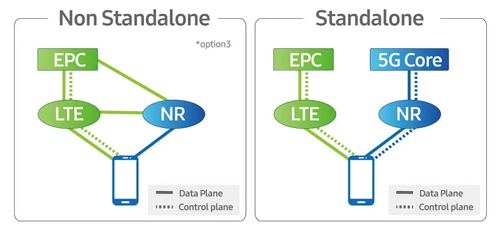
5G NSA (Non Standalone) uses LTE (4G) with an additional layer “bolted on” that uses 5G on the radio interface to provide “5G” speeds to users, while reusing the existing LTE (Evolved Packet Core) core and VoLTE for voice / SMS.
From an operator perspective there is almost no change required in the network to support NSA 5G, other than in the RAN, and almost all the 5G networks in commercial use today use 5G NSA.
5G NSA is great, it gives the user 5G speeds for users with phones that support it, with no change to the rest of the network needed.
Standalone 5G on the other hand requires an a completely new core network with all the trimmings.
While it is possible to handover / interwork with LTE/4G (Inter-RAT Handovers), this is like 3G/4G interworking, where each has a different core network. Introducing 5G standalone touches every element of the network, you need new nodes supporting the new standards for charging, policy, user plane, IMS, etc.
Scope
There’s an old adage that businesses spend money for one of three reasons:
To Save Money (Which we’ll cover in this post)
To make more Money (Covered next – Will link when published)
Because they have to (Regulatory compliance, insurance, taxes, etc)
Let’s look at 5G Standalone in each of these contexts:
5G Cost Savings – Counterpoint: The cost-benefit doesn’t stack up
As an operator with an existing deployed 4G LTE network, deploying a new 5G standalone network will not save you money.
From an capital perspective this is pretty obvious, you’re going to need to invest in a new RAN and a new core to support this, but what about from an opex perspective?
Claim: 5G RAN is more efficient than 4G (LTE) RAN
Spectrum is both finite and expensive, so MNOs must find the most efficient way to use that spectrum, to squeeze the most possible value out of it.
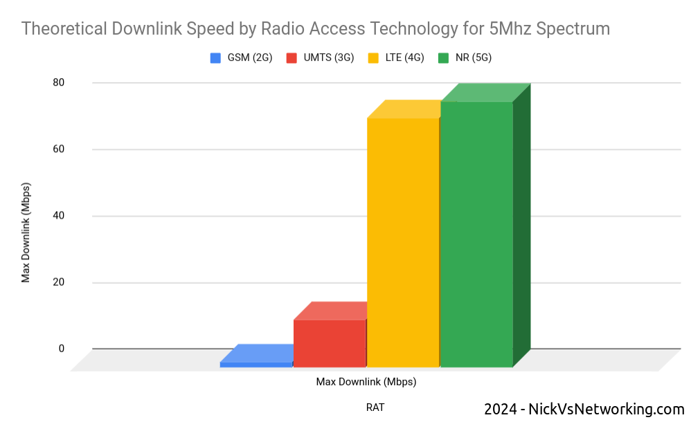
In rough numbers, we can say we get 5x the spectral efficiency by moving from 3G to 4G. This means we can carry 5.2x more with the same spectrum on 4G than we can on 3G – A very compelling reason to upgrade.
The like-for-like spectral efficiency of 5G is not significantly greater than that of LTE.
In numbers the same 5Mhz of spectrum we refarmed from UMTS (3G) to 4G (LTE) provided a 5x gain in efficiency to deliver 75Mbps on LTE. The same configuration refarmed to 5G-NR would provide 80Mbps.
Refarming spectrum from 4G (LTE) to 5G (NR) only provides a 6% increase in spectral efficiency.
While 6% is not nothing, if refarmed to a 5G standalone network, the spectrum can no longer be used by LTE only devices (Unless Dynamic Spectrum Sharing is used which in itself leads to efficiency losses), which in itself reduces the efficiency and would add additional load to other layers.
The crazy speeds demonstrated by 5G are not due to meaningful increases in efficiency, but rather the ability to use more spectrum, spectrum that operators need to purchase at auction, purchase equipment to utilize and pay to run.
Claim: 5G Standalone Core is Cheaper to operate as it is “Cloud Native”
It has been widely claimed that the shift for the 5G Core Architecture to being “Cloud Native” can provide cost savings.
Operators should regard this in a skeptical manner; after all, we’ve been here before.
Did moving from big-iron to VNFs provide the promised cost savings to operators?
For many operators the shift from hardware to software added additional complexity to the network and increased the headcount to support this.
What were once big-iron appliances dedicated to one job, that sat in the corner and chugged away, are now virtual machines (VNFs). Many operators have naturally found themselves needing a larger team to manage the virtual environment, compared to the size of the team they needed to just to plug power and data into a big box in an exchange before everything was virtualized.
Introducing a “Cloud Native” Kubernetes layer on top of the VNF / virtualization layer, on top of the compute layer, leaves us with a whole lot of layers. All of which require resources to be maintain, troubleshoot and kept running; each layer having associated costs for staffing, licensing and support.
Many mid size enterprises rushed into “the cloud” for the promised cost savings only to sheepishly admit it cost more than the expected.
Almost none of the operators are talking about running these workloads in the public cloud, but rather “Private Clouds” built on-premises, using “Cloud Native” best practices.
One of the central arguments about cloud revolves around “elastic scaling” where the network can automatically scale to match demand; think extra instances spun up a times of peak demand and shut down when the demand drops.
I explain elastic scaling to clients as having to move people from one place to another. Most of the time, I’m just moving myself, a push bike is fine, or I’ve got a 4 seater car, but occasionally I’ll need to move 25 people and for that I’d need a bus.
If I provide the transportation myself, I need to own a bike, a car and a bus.
But if use the cloud I can start with the push bike, and as I need to move more people, the “cloud” will provide me the vehicle I need to move the people I need to move at that moment, and I’ll just pay for the time I need the bus, and when I’m done needing the bus, I drop back to the (cheaper) push bike when I’m not moving lots of people.
While telecom operators are going to provide the servers to run this in “On-prem-cloud”, they need to dimension for the maximum possible load. This means they need to own a bike/car/bus, even if they’re not using it most of the time, and there’s really no cost savings to having a bus but not using it when you’re not paying by the hour to hire it.
Infrastructure aside, introducing a Standalone 5G Core adds another core network to maintain. Alongside the Circuit Switched Core (MSC/GGSN/SGSN) serving 2G/3G subscribers, Evolved Packet Core serving 4G (LTE) and 5G-NSA subscribers, adding a 5G Standalone Core to for the 5G-SA subscribers served by the 5G SA cells, is going to be more work (and therefore cost).
While the majority of operators have yet to turn off their 2G/3G core networks, introducing another core network to run in parallel is unlikely to lead to any cost savings.
Claim: Upgrading now can save money in the Future / Future Proofing
Life cycles of telecommunications are two fold, one is the equipment/platform life cycle (like the RAN components or Core network software being used to deliver the service) the other is the technology life cycle (the generation of technology being used).
The technology lifecycles in telecommunications are vastly longer than that for regular tech.
GSM (2G) was introduced into the UK in 1991, and will be phased out starting in 2033, a 42 year long technology life cycle.
No vendor today could reasonably expect the 5G hardware you deploy in 2024 to still be in production in 2066 – The platform/equipment life cycle is a lot shorter than the technology life cycle.
Operators will to continue relying on LTE (4G) well into the late 2030s.
I’d wager that there is not a single piece of equipment in the Vodafone UK GSM network today, that was there in 1991. I’d go even further to say that any piece of equipment in the network today, didn’t even replace the 1991 equipment, but was probably 3 or 4 generations removed from the network built in 1991.
For most operators, RAN replacements happen between 4 to 7 years, often with targeted augmentation / expansion as needed in the form of adding extra layers / sectors between these times.
The question operators should be asking is therefore not what will I need to get me through to 2066, but rather what will I need to get to 2030?
The majority of operators outside the US today still operate a 2G or 3G network, generally with minimal bandwidth to support legacy handsets and devices, while the 4G (LTE) network does most of the heavy lifting for carrying user traffic. This is often with the aid of an additional 5G-NSA (Non-Standalone) layer to provide additional capacity.
Is there a cost saving angle to adding support for 5G-Standalone in addition to 2G/3G/4G (LTE) and 5G (Non-Standalone) into your RAN?
A logical stance would be that removing layers / technologies (such as 2G/3G sunsetting) would lead to cost savings, and adding a 5G Standalone layer would increase cost.
All of the RAN solutions on the market today from the major vendors include support for both Standalone 5G and Non Standalone, but the feature licensing for a non-standalone 5G is generally cheaper than that for Standalone 5G.
The question operators should be asking is on what timescale do I need Standalone 5G?
If you’ve rolled out 5G-NSA today, then when are you looking to sunset your LTE network? If the answer is “I hope to have long since retired by that time”, then you’ve just answered that question and you don’t need to licence / deploy 5G-SA in this hardware refresh cycle.
Other Cost Factors
Roaming: The majority of roaming traffic today relies on 2G/3G for voice. VoLTE roaming is (finally) starting to establish a foothold, but we are a long way from ubiquitous global roaming for LTE and VoLTE, and even further away for 5G-SA roaming. Focusing on 5G roaming will enable your network for roaming use by a miniscule number of operators, compared to LTE/VoLTE roaming which covers the majority of the operators in the developed world who can utilize your service.
I decided to split this into 3 posts, next I’ll post the “5G can make us more money” post and finally a “5G because we have to” post. I’ll post that on LinkedIn / Twitter / Mailing list, so stick around, and feel free to trash me in the comments.
Even before 5G was released, the arms race to claim the “fastest” speeds on LTE, NSA and SA networks has continued, with pretty much every operator claiming a “first” or “fastest”.
I myself have the fastest 5G network available* but I thought I’d look at how big the values are we can put in for speed, these are the Maximum Bitrate Values (like AMBR) we can set on an APN/DNN, or on a Charging Rule.
*Measurement is of the fastest 5G network in an eastward facing office, operated by a person named Nick, in a town in Australia. Other networks operated by people other than those named Nick in eastward facing office outside of Australia were not compared.
The answer for Release 8 LTE is 4294967294 bytes per second, aka 4295 Mbps 4.295 Gbps.
Not bad, but why this number?
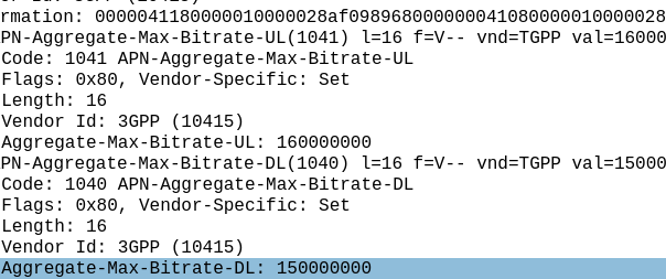
The Max-Requested-Bandwidth-DL AVP tells the PGW the max throughput allowed in bits per second. It’s a Unsigned32 so max value is 4294967294, hence the value.
But come release 15 some bright spark thought we may in the not to distant future break this barrier, so how do we go above this?
The answer was to bolt on another AVP – the “Extended-Max-Requested-BW-DL” AVP ( 554 ) was introduced, you might think that means the max speed now becomes 2x 4.295 Gbps but that’s not quite right – The units was shifted.
This AVP isn’t measuring bits per second it’s measuring kilobits per second.
So the standard Max-Requested-Bandwidth-DL AVP gives us 4.3 Gbps, while the Extended-Max-Requested-Bandwidth gives us a 4,295 Gbps.
We add the Extended-Max-Requested-Bandwidth AVP (4295 Gbps) onto the Max-Requested Bandwidth AVP (4.3 Gbps) giving us a total of 4,4299.3 Gbps.
If you’ve ever worked in roaming, you’ll probably have had the misfortune of dealing with Transferred Account Procedures aka TAP files.
It’s used for billing a 2G GSM call right up to 5G data usage, if you use a service while roaming, somewhere in the world there’s a TAP file with your usage in it.
A brief history of TAP
TAP was originally specified by the GSMA in 1991 as a standard CDR interchange format between operators, for use in roaming scenarios.
Notice I said GSMA – Not 3GPP – This means there’s no 3GPP TS docs for this, it’s defined by the industry lobby group’s members, rather than the standards body.
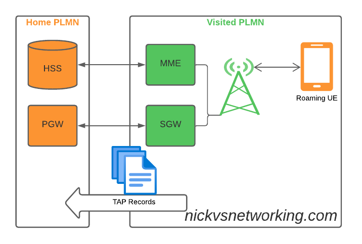
So what does this actually mean? Well, if you’re MNO A and a customer from MNO B roams into your network, all the calls, SMS and data consumed by the roaming subscriber from MNO B will need to be billed to MNO B, by you, MNO A.
If a network operator wants to get paid for traffic used on their network by roaming subscribers, they’d better send out a TAP file to the roamer’s home network.
TAP is the file format generated my MNO A and sent to MNO B, containing all the usage charges that subscribers from MNO B have racked up while roaming into your network.
These are broken down into “Transactions” (CDRs), for events like making a call, connecting a PDN session and consuming data, or sending a text.
In the beginning of time, GSM provided only voice calling service. This meant that the only services a subscriber could consume while roaming was just making/receiving voice calls which were billed at the end of each month. – This meant billing was equally simple, every so often the visisted network would send the TAP files for the voice calls made by subscribers visited other networks, to the home networks, which would markup those charges, and add them onto the monthly invoice for each subscriber who was roaming.
But of course today, calling accounts for a tiny amount of usage on the network, but this happened gradually while passing through the introduction of SMS, CAMEL services, prepaid services, mobile data, etc. For all these services that could be offered, the TAP format had to evolve to handle each of these scenarios.
As we move towards a flat IP architecture, where voice calls and SMS sent while roaming are just data, TAP files for 4G and 5G networks only need to show data transactions, so the call objects, CAMEL parameters and SMS objects are all falling by the wayside.
What’s inside a TAP File
TAP uses the most beloved of formats – ASN1 to encode the data. This means it is strictly formatted and rigidly specified.
Each file contains a Sequence Number which is a monotonically increasing number, which allows the receiver to know if any files have been missed between the file that’s being currently parsed, an the previous file.
They also have a recipient and sender TADIG code, which is a code allocated by GSMA that uniquely identifies the sender and the recipient of the file.
The TAP records exist in one of two common format, Notification Records and transferBatch records.
These files are exchanged between operators, in practice this means “Dumped on an FTP server as agreed between the two”.
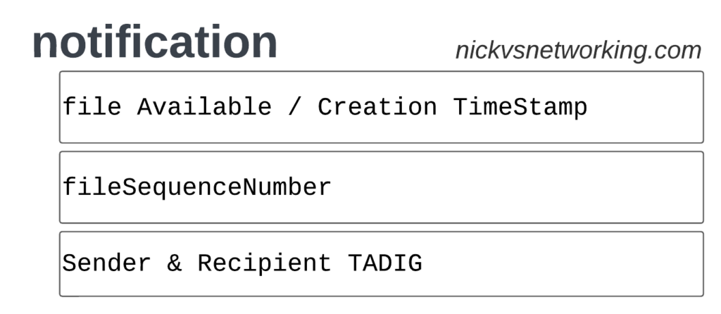
TAP Notification Records
Notifications are the simplest of TAP records and are used when there aren’t any CDRs for roaming events during the time period the TAP file covers.
These are essentially blank TAP files generated by the visited network to let the home network know it’s still there, but there are no roaming subs consuming services in that period.
Notification files are really simple, let’s take a look as one shown as JSON:
When we have services to bill and records to charge, that’s when instead we generate a transferBatch record.
It looks something like this:
There’s a lot going on in here, so let’s break it down section by section.
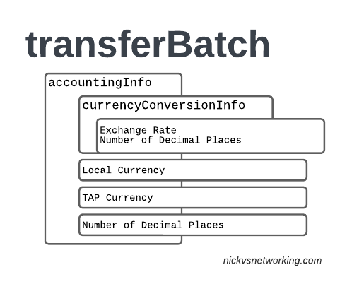
accountingInfo
The accountingInfo section specifies the currency, exchange rate parameters.
Keep in mind a TAP record generated by an operator in the US, would use USD, while the receiver of the file may be a European MNO dealing in EUR.
This gets even more complicated if you’re dealing with more obscure currencies where an intermediary currency is used, that’s where we bring in SDRs (“Special Drawing Right”) that map to the dollar value to be charged, kinda – the roaming agreement defines how many SDRs are in a dollar, in the example below we’re not using any, but you do see it.
When it comes to numbers and decimal places, TAP doesn’t exactly make it easy.
Significant Digits are defined by counting the first number before the decimal point and all the numbers to the right of the decimal point, so for example the number 1.234 would be 4 significant digits (1 digit before the decimal point and 3 digits after it).
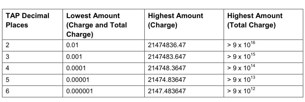
Decimal Places are not actually supported for the Value fields in the TAP file. This is tricky because especially today when roaming tariffs are quite low, these values can be quite small, and we need to represent them as an integer number. TAP defines decimal places as the number of digits after the decimal place.
When it comes to the maximum number of decimal places, this actually impacts the maximum number we can store in the field – as ASN1 strictly enforce what we put in it.
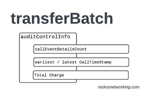
The auditControlInfo section contains the number of CDRs (callEventDetailsCount) contained in the TAP file, the timestamp of the first and last CDR in the file, the total charge and any tax charged.
All of the currency information was provided in the accountingInfo so this is just giving us our totals.
A CDR has 30 days from the time it was generated / service consumed by the roamer, to be baked into a TAP file. After this we can no longer charge for it, so it’s important that the earliestCallTimeStamp is not more than 30 days before the fileCreationTimeStamp seen in batchControlInfo.
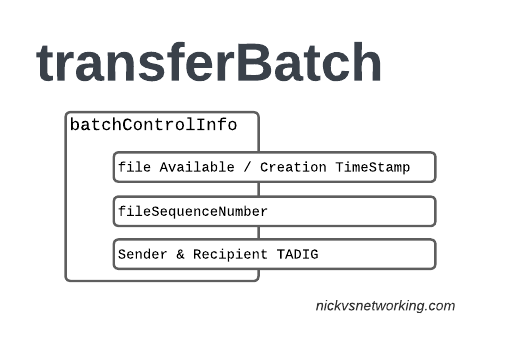
batchControlInfo
The batchControlInfo section specifies the time the TAP file became available for transfer, the time the file was created (usually the same), the sequence number and the sender / recipient TADIG codes.
As mentioned earlier, we track sequence number so the receiver can know if a TAP file has been missed; for example if you’ve got TAP file 1 and TAP file 3 comes in, you can determine you’ve missed TAP file 2.
Now we’re getting to the meat & potatoes of our TAP record, the CDRs themselves.
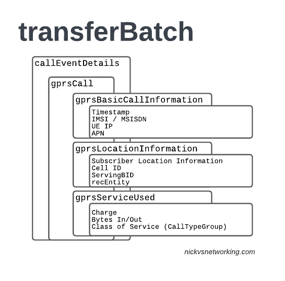
In LTE networks these are just records of data consumption, so let’s take a look inside the gprsCall records under callEventDetails:
In the gprsBasicCallInformation we’ve got as the name suggests the basic info about the data usage event. The time when the session started, the charging ID, the IMSI and the MSISDN of the subscriber to charge, along with their IP and the APN used.
Next up we have the gprsLocationInformation – rates and tariffs may be set based on the location of the subscriber, so we need to identify the area the sub was using the services to select correct tariff / rate for traffic in this destination.
The recEntity is the index number of the SGW / PGW used for the transaction (more on that later).
Next we have the gprsServiceUsed which, again as the name suggests, details the services used and the charge.
chargeDetailList contains the charged data (Made up of dataVolumeIncoming + dataVolumeOutgoing) and the cost.
The chargeableUnits indicates the actual data consumed, however most roaming agreements will standardise on some level of rounding, for example rounding up to the nearest Kilobyte (1024 bytes), so while a sub may consume 1025 bytes of data, they’d be billed for 2045 bytes of data. The data consumed is indicated in the chargeableUnits which indicates how much data was actually consumed, before any rounding policies where applied, while the amount that is actually charged (When taking into account rounding policies) isindicated inside Charged Units.
In the example below data usage is rounded up to the nearest 1024 bytes, 134390 bytes rounds up to the nearest 1024 gives you 135168 bytes.
As this is data we’re talking bytes, but not all bytes are created equal!
VoLTE traffic, using a QCI1 bearer is more valuable than QCI 9 cat videos, and TAP records take this into account in the Call Type Groups, each of which has a different price – Call Type Level 1 indicates the type of traffic, for S8 Home Routed LTE Traffic this is 10 (HGGSN/HP-GW), while Call Type Level 2 indicates the type of traffic as mapped to QCI values:
So Call Type Level 2 set to 20 indicates that this is “20 Unspecified/default LTE QCIs”, and Call Type Level 3 can be set to any value based on a defined inter-operator tariff.
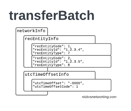
recEntityType 7 means a PGW and contains the IP of the PGW in the Home PLMN, while recEntityType 8 means SGW and is the SGW in the Visited PLMN.
So this means if we reference recEntityCode 2 in a gprsCall, that we’re referring to an SGW at 1.2.3.5.
Lastly also got the utcTimeOffsetInfo to indicate the timezones used and assign a unique code to it.
Using the Records
We as humans? These records aren’t meant for us.
They’re designed to be generated by the Visited PLMN and sent to to the home PLMN, which ingests it and pays the amount specified in the time agreed.
Generally this is an FTP server that the TAP records get dumped into, and an automated bank transfer job based on the totals for the TAP records.
Testing of the TAP records is called “TADIG Testing” and it’s something we’ll go into another day, but in essence it’s validating that the output and contents of the files meet what both operators think is the contract pricing and specifications.
So that’s it! That’s what’s in a TAP record, what it does and how we use it!
GSMA are introducing BCE – Billing & Charging Evolution, a new standard, designed to last for the next 30+ years like TAP has. It’s still in its early days, but that’s the direction the GSMA has indicated it would like to go.
Misunderstood, under appreciated and more capable than people give it credit for, is our PCRF.
But what does it do?
Most folks describe the PCRF in hand wavy-terms – “it does policy and charging” is the answer you’ll get, but that doesn’t really tell you anything.
So let’s answer it in a way that hopefully makes some practical sense, starting with the acronym “PCRF” itself, it stands for Policy and Charging Rules Function, which is kind of two functions, one for policy and one for rules, so let’s take a look at both.
Policy
In cellular world, as in law, policy is the rules.
For us some examples of policy could be a “fair use policy” to limit customer usage to acceptable levels, but it can also be promotional packages, services like “free Spotify” packages, “Voice call priority” or “unmetered access to Nick’s Blog and maximum priority” packages, can be offered to customers.
All of these are examples of policy, and to make them work we need to target which subscribers and traffic we want to apply the policy to, and then apply the policy.
Charging Rules
Charging Rules are where the policy actually gets applied and the magic happens.
It’s where we take our policy and turn it into actionable stuff for the cellular world.
Let’s take an example of “unmetered access to Nick’s Blog and maximum priority” as something we want to offer in all our cellular plans, to provide access that doesn’t come out of your regular usage, as well as provide QCI 5 (Highest non dedicated QoS) to this traffic.
To achieve this we need to do 3 things:
Profile the traffic going to this website (so we capture this traffic and not regular other internet traffic)
Charge it differently – So it’s not coming from the subscriber’s regular balance
Up the QoS (QCI) on this traffic to ensure it’s high priority compared to the other traffic on the network
So how do we do that?
Profiling Traffic
So the first step we need to take in providing free access to this website is to filter out traffic to this website, from the traffic not going to this website.
Let’s imagine that this website is hosted on a single machine with the IP 1.2.3.4, and it serves traffic on TCP port 443. This is where IPFilterRules (aka TFTs or “Traffic Flow Templates”) and the Flow-Description AVP come into play. We’ve covered this in the past here, but let’s recap:
IPFilterRules are defined in the Diameter Base Protocol (IETF RFC 6733), where we can learn the basics of encoding them,
They take the format:
action dir proto from src to dst
The action is fairly simple, for all our Dedicated Bearer needs, and the Flow-Description AVP, the action is going to be permit. We’re not blocking here.
The direction (dir) in our case is either in or out, from the perspective of the UE.
Next up is the protocol number (proto), as defined by IANA, but chances are you’ll be using 17 (UDP) or 6 (TCP).
The from value is followed by an IP address with an optional subnet mask in CIDR format, for example from 10.45.0.0/16would match everything in the 10.45.0.0/16 network.
Following from you can also specify the port you want the rule to apply to, or, a range of ports.
Like the from, the tois encoded in the same way, with either a single IP, or a subnet, and optional ports specified.
And that’s it!
So let’s create a rule that matches all traffic to our website hosted on 1.2.3.4 TCP port 443,
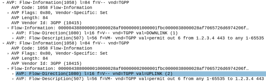
permit out 6 from 1.2.3.4 443 to any 1-65535
permit out 6 from any 1-65535 to 1.2.3.4 443
All this info gets put into the Flow-Information AVPs:
With the above, any traffic going to/from 1.23.4 on port 443, will match this rule (unless there’s another rule with a higher precedence value).
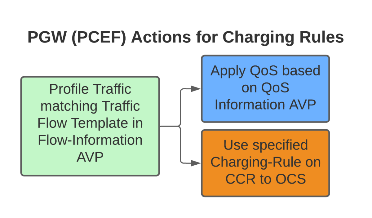
Charging Actions
So with our traffic profiled, the next question is what actions are we going to take, well there’s two, we’re going to provide unmetered access to the profiled traffic, and we’re going to use QCI 4 for the traffic (because you’ll need a guaranteed bit rate bearer to access!).
Charging-Group for Profiled Traffic
To allow for Zero Rating for traffic matching this rule, we’ll need to use a different Rating Group.
Let’s imagine our default rating group for data is 10000, then any normal traffic going to the OCS will use rating group 10000, and the OCS will apply the specific rates and policies based on that.
Rating Groups are defined in the OCS, and dictate what rates get applied to what Rating Groups.
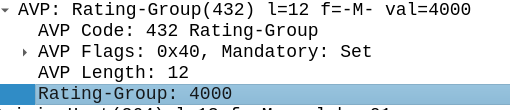
For us, our default rating group will be charged at the normal rates, but we can define a rating group value of 4000, and set the OCS to provide unlimited traffic to any Credit-Control-Requests that come in with Rating Group 4000.
This is how operators provide services like “Unlimited Facebook” for example, a Charging Rule matches the traffic to Facebook based on TFTs, and then the Rating Group is set differently to the default rating group, and the OCS just allows all traffic on that rating group, regardless of how much is consumed.
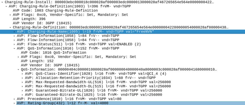
Inside our Charging-Rule-Definition, we populate the Rating-Group AVP to define what Rating Group we’re going to use.
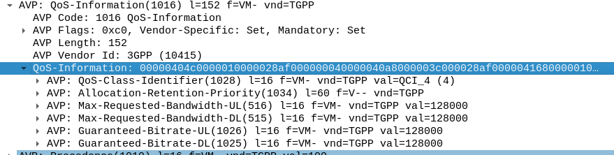
Setting QoS for Profiled Traffic
The QoS Description AVP defines which QoS parameters (QCI / ARP / Guaranteed & Maximum Bandwidth) should be applied to the traffic that matches the rules we just defined.
As mentioned at the start, we’ll use QCI 4 for this traffic, and allocate MBR/GBR values for this traffic.
Putting it Together – The Charging Rule
So with our TFTs defined to match the traffic, our Rating Group to charge the traffic and our QoS to apply to the traffic, we’re ready to put the whole thing together.
So here it is, our “Free NVN” rule:
I’ve attached a PCAP of the flow to this post.
In our next post we’ll talk about how the PGW handles the installation of this rule.
Next we’ll need to define our rt_pyform config, this is a super simple 3 line config file that specifies the path of what we’re doing:
DirectoryPath = "."        # Directory to search
ModuleName = "script"      # Name of python file. Note there is no .py extension
FunctionName = "transform" # Python function to call
The DirectoryPath directive specifies where we should search for the Python code, and ModuleName is the name of the Python script, lastly we have FunctionName which is the name of the Python function that does the rewriting.
Now let’s write our Python function for the transformation.
The Python function much have the correct number of parameters, must return a string, and must use the name specified in the config.
The following is an example of a function that prints out all the values it receives:
Note the order of the arguments and that return is of the same type as the AVP value (string).
We can expand upon this and add conditionals, let’s take a look at some more complex examples:
def transform(appId, flags, cmdCode, HBH_ID, E2E_ID, AVP_Code, vendorID, value):
    print('[PYTHON]')
    print(f'|-> appId: {appId}')
    print(f'|-> flags: {hex(flags)}')
    print(f'|-> cmdCode: {cmdCode}')
    print(f'|-> HBH_ID: {hex(HBH_ID)}')
    print(f'|-> E2E_ID: {hex(E2E_ID)}')
    print(f'|-> AVP_Code: {AVP_Code}')
    print(f'|-> vendorID: {vendorID}')
    print(f'|-> value: {value}')
    #IMSI Translation - if App ID = 16777251 and the AVP being evaluated is the Username
    if (int(appId) == 16777251) and int(AVP_Code) == 1:
        print("This is IMSI '" + str(value) + "' - Evaluating transformation")
        print("Original value: " + str(value))
        value = str(value[::-1]).zfill(15)
The above look at if the App ID is S6a, and the AVP being checked is AVP Code 1 (Username / IMSI ) and if so, reverses the username, so IMSI 1234567 becomes 7654321, the zfill is just to pad with leading 0s if required.
Now let’s do another one for a Realm Rewrite:
def transform(appId, flags, cmdCode, HBH_ID, E2E_ID, AVP_Code, vendorID, value):

    #Print Debug Info
    print('[PYTHON]')
    print(f'|-> appId: {appId}')
    print(f'|-> flags: {hex(flags)}')
    print(f'|-> cmdCode: {cmdCode}')
    print(f'|-> HBH_ID: {hex(HBH_ID)}')
    print(f'|-> E2E_ID: {hex(E2E_ID)}')
    print(f'|-> AVP_Code: {AVP_Code}')
    print(f'|-> vendorID: {vendorID}')
    print(f'|-> value: {value}')
    #Realm Translation
    if int(AVP_Code) == 283:
        print("This is Destination Realm '" + str(value) + "' - Evaluating transformation")
    if value == "epc.mnc001.mcc001.3gppnetwork.org":
        new_realm = "epc.mnc999.mcc999.3gppnetwork.org"
        print("translating from " + str(value) + " to " + str(new_realm))
        value = new_realm
    else:
        #If the Realm doesn't match the above conditions, then don't change anything
        print("No modification made to Realm as conditions not met")
    print("Updated Value: " + str(value))
In the above block if the Realm is set to epc.mnc001.mcc001.3gppnetwork.org it is rewritten to epc.mnc999.mcc999.3gppnetwork.org, hopefully you can get a handle on the sorts of transformations we can do with this – We can translate any string type AVPs, which allows for hostname, realm, IMSI, Sh-User-Data, Location-Info, etc, etc, to be rewritten.
NB-IoT introduces support for NIDD – Non-IP Data Delivery (NIDD) which is one of the cool features of NB-IoT that’s gaining more widespread adoption.
Let’s take a deep dive into NIDD.
The case against IP for IoT
In the over 40 years since IP was standardized, we’ve shoehorned many things onto IP, but IP was never designed or optimized for low power, low throughput applications.
For the battery life of an IoT device to be measured in years, it has to be very selective about what power hungry operations it does. Transmitting data over the air is one of the most power-intensive operations an IoT device can perform, so we need to do everything we can to limit how much data is sent, and how frequently.
Use Case – NB-IoT Tap
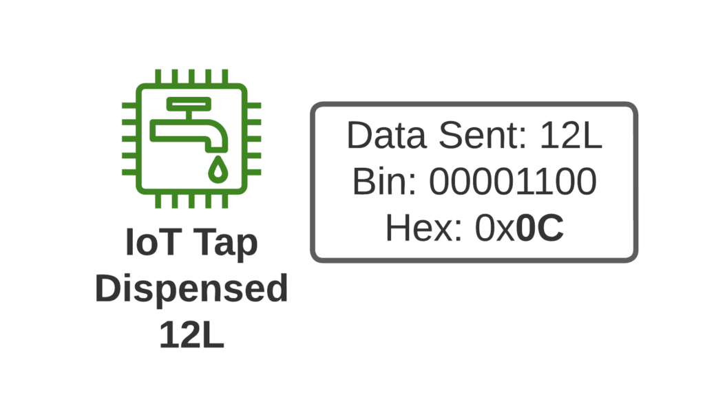
Let’s imagine we’re launching an IoT tap that transmits information about water used, as part of our revolutionary new “Water as a Service” model (WaaS) which removes the capex for residents building their own water treatment plant in their homes, and instead allows dynamic scaling of waterloads as they move to our new opex model.
If I turn on the tap and use 12L of water, when I turn off the tap, our IoT tap encodes the usage onto a single byte and sends the usage information to our rain-cloud service provider.
So we’re not constantly changing the batteries in our taps, we need to send this one byte of data as efficiently as possible, so as to maximize the battery life.
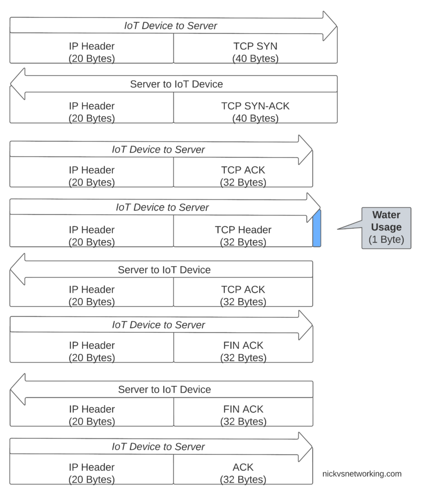
If we were to transport our data on TCP, well we’d need a 3 way handshake and several messages just to transmit the data we want to send.
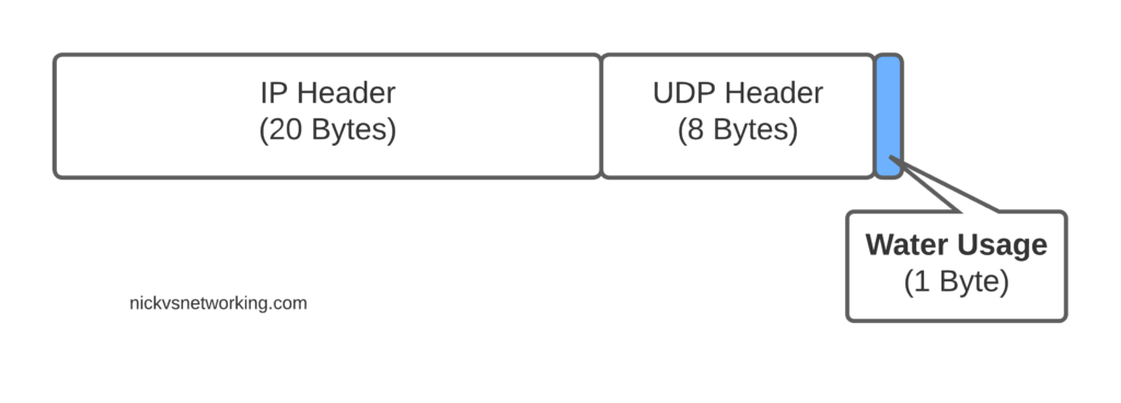
Let’s see how our one byte of data would look if we transported it on TCP.
That sliver of blue in the diagram is our usage component, the rest is overhead used to get it there. Seems wasteful huh?
Sure, TCP isn’t great for this you say, you should use UDP! But even if we moved away from TCP to UDP, we’ve still got the IPv4 header and the UDP header wasting 28 bytes.
For efficiency’s sake (To keep our batteries lasting as long as possible) we want to send as few messages as possible, and where we do have to send messages, keep them very short, so IP is not a great fit here.
Enter NIDD – Non-IP Data Delivery.
Through NIDD we can just send the single hex byte, only be charged for the single hex byte, and only stay transmitting long enough to send this single byte of hex (Plus the NBIoT overheads / headers).
Compared to UDP transport, NIDD provides us a reduction of 28 bytes of overhead for each message, or a 96% reduction in message size, which translates to real power savings for our IoT device.
In summary – the more sending your device has to do, the more battery it consumes. So in a scenario where you’re trying to maximize power efficiency to keep your batter powered device running as long as possible, needing to transmit 28 bytes of wasted data to transport 1 byte of usable data, is a real waste.
Delivering the Payload
NIDD traffic is transported as raw hex data end to end, this means for our 1 byte of water usage data, the device would just send the hex value to be transferred and it’d pop out the other end.
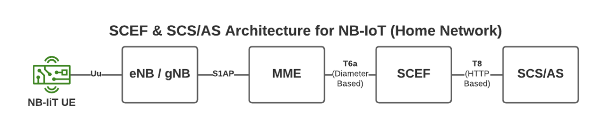
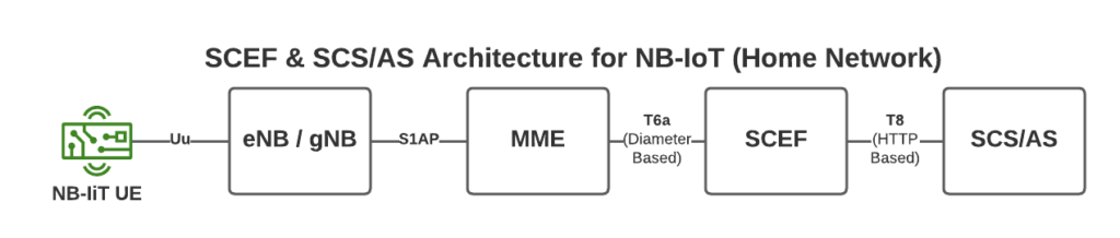
To support this we introduce a new network element called the SCEF –Service Capability Exposure Function.
From a developer’s perspective, the SCEF is the gateway to our IoT devices. Through the RESTful API on the SCEF (T8 API), we can send and receive raw hex data to any of our IoT devices.
When one of our Water-as-a-Service Taps sends usage data as a hex byte, it’s the software talking on the T8 API to the SCEF that receives this data.
Data of course needs to be addressed, so we know where it’s coming from / going to, and T8 handles this, as well as message reliability, etc, etc.
This is a telco blog, so we should probably cover the MME connection, the MME talks via Diameter to the SCEF. In our next post we’ll go into these signaling flows in more detail.
If you’re wondering what the status of Open Source SCEF implementations are, then you may have already guessed I’m working on one!
Hopefully by now you’ve got a bit of an idea of how NIDD works in NB-IoT, and in our next posts we’ll dig deeper into the flows and look at some PCAPs together.
Having a central pair of Diameter routing agents allows us to drastically simplify our network, but what if we want to perform some translations on AVPs?
For starters, what is an AVP transformation? Well it’s simply rewriting the value of an AVP as the Diameter Request/Response passes through the DRA. A request may come into the DRA with IMSI xxxxxx and leave with IMSI yyyyyy if a translation is applied.
So why would we want to do this?
Well, what if we purchased another operator who used Realm X, and we use Realm Y, and we want to link the two networks, then we’d need to rewrite Realm Y to Realm X, and Realm X to Realm Y when they communicate, AVP transformations allow for this.
If we’re an MVNO with hosted IMSIs from an MNO, but want to keep just the one IMSI in our HSS/OCS, we can translate from the MNO hosted IMSI to our internal IMSI, using AVP transformations.
If our OCS supports only one rating group, and we want to rewrite all rating groups to that one value, AVP transformations cover this too.
There are lots of uses for this, and if you’ve worked with a bit of signaling before you’ll know that quite often these sorts of use-cases come up.
So how do we do this with freeDiameter?
To handle this I developed a module for passing each AVP to a Python function, which can then apply any transformation to a text based value, using every tool available to you in Python.
In the next post I’ll introduce rt_pyform and how we can use it with Python to translate Diameter AVPs.