PFCP includes a “Redirect Information” IE, which if set, allows you to change the forwarding action in PFCP to Redirect traffic.
We use this for walled garden redirects, when the OCS reports credit exhausted to the PGW-C, the PGW-C can tell the UPF (PGW-U) that all the traffic from a given subscriber should be redirected to a captive portal / walled garden, like a “Topup Now Page” you’d be used to seeing on Airport WiFi.
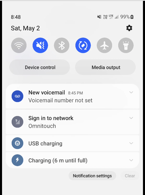
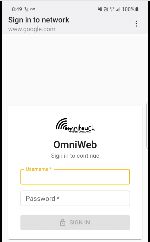
“Sign in to network” prompt presented on Cellular
Here’s what the spec says:
8.37. Redirect-Server AVP The Redirect-Server AVP (AVP Code 434) is of type Grouped and contains the address information of the redirect server (e.g., HTTP redirect server, SIP Server) with which the end user is to be connected when the account cannot cover the service cost. It MUST be present when the Final-Unit-Action AVP is set to REDIRECT. It is defined as follows (per the grouped-avp-def of RFC 3588 [DIAMBASE]): Redirect-Server ::= < AVP Header: 434 > { Redirect-Address-Type } { Redirect-Server-Address }
So how does this work in practice?
Once upon a time, you’d just intercept all HTTP request and serve your own content, but it’s not 2005 on Starbucks WiFi anymore, and SSL is everywhere.
Luckily this is a (mostly) solved problem, Apple has “Captive Network Assistant” that probes http://captive.apple.com/hotspot-detect.html and checks for a specific response, Google’s Android has http://connectivitycheck.gstatic.com/generate_204 and does the same thing.
But before I can tell you what we do, I’ll show you what we’re not doing before we do the doing so you can see what the do does by looking at what happens when we don’t – Clear?
Before we send any Session Modification Request with redirect I can do a DNS lookup, here’s an example from our test jig that goes to Facebook:
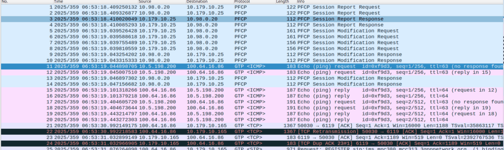
A Record lookup for facebook.com resolving to 57.145.8.1
This is just a regular A record DNS query wrapped up in GTP-U as it’d look from a eNB/gNB/SGW that gets an answer back also in GTP-U.
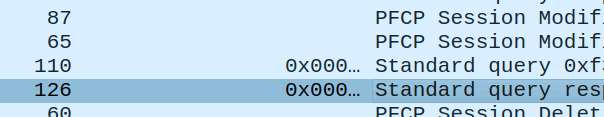
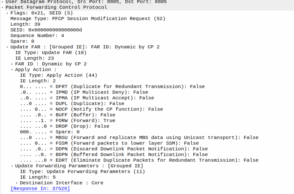
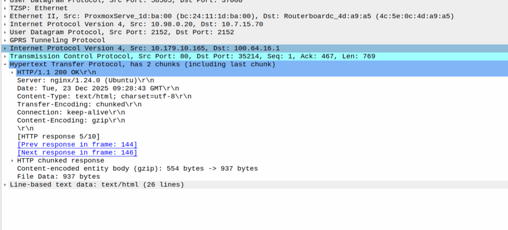
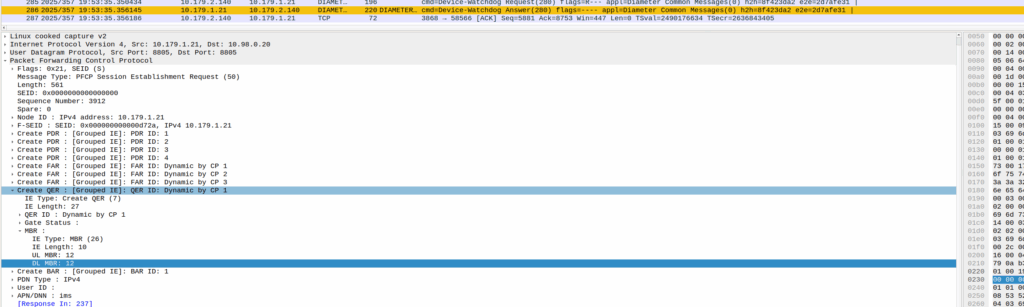
As we’ve already got a session up in our case, the SMF or PGW-C we sends the PFCP Session Modification Request I shared in the screenshot earlier to the UPF.
The Redirect Server Address in the Redirect Information IE in PFCP
We do a few things on the UPF at this point, the first, is that we block forwarding access to all IPs except 10.179.2.135 (The redirect server in the screenshot), and we steal / intercept all DNS queries.
This means if you query facebook.com after the Redirect Information is in place, you get back an A-Record answer for facebook.com but it’s telling you Facebook lives on our redirect server.
We’ve got a whitelist on our UPF for certain domains, so if we’re sending you to a self-signup page, you’re going to need to be able to hit our payment processors portals (Stripe, Paypal, etc), so we need to allow their domains, but we don’t know their IPs, so instead we do server side DNS lookups (via our DNS servers before you sneaky kids get any other ideas) for the whitelsited domains, and if it’s on our DNS whitelist, we allow resolution to those domains and allow access to those IPs returned in the DNS response.
In my lab I’m redirecting HTTP traffic to a management server
Turning it off just involves sending another PFCP Session Modification Request but without the redirect information.
We support a network in Alaska, and one of the guys we work with there – John – has a story (which I’ll steal here) where he gets a phone call late at night from someone saying they’re in the US Air Force, and uh, they’ve, uh, lost a plane. And since John works for the phone company, he wouldn’t have any idea where it is would you? They ask him.
As a matter of fact, John could see the last cell the SIM the pilot was carrying was attached to, they sent a helicopter out and found the pilot, who survived.
This was a long time ago, and he was able to pin the location down to a cell (sector), and lookup which direction the sectors were pointing for that cell and the location of it, to give a pretty good idea of the general search area.
Now that everyone carries a GPS in their pockets, the level of accuracy here is a lot more than just which cell are you served by (although that’s a lot of accuracy anyway, and not to be ignored).
There’s significant privacy implications here and a lot of misinformation about pinging cell towers and “zoom enhance” stuff.
I figured I’d actually share how this works IRL – There’s nothing ‘secret‘ here – All of this stuff is in the 3GPP standards which outline how mobile networks should behave.
There’s roughly 4 levels of accuracy in cell phone networks, we’ll cover each one, and how the network treats it.
(I’m talking 4G/5G here as most of the world has moved on or is already moving on from 2G/3G)
Tracking Area Level Accuracy
Cell sites get grouped into tracking areas, they’re kinda like broadcast domains in TCP/IP networking, when you need to “page” (find) a phone that’s “idle” (sleeping) you page the tracking area.
Tracking Area sizing has sweet spots, you want more than a few cells, commonly about a dozen or so in the same geographic area get lumped into the same tracking area. In regional areas you might have a large geographic area – Up to a few hundred Km in regional Australia for example, lumped into a single tracking area, whereas in a city that might be a single city block.
If you move between cells inside the same tracking area, then your phone doesn’t need to say to the network “hey I’m moving cells” – It’s only if we go over to a new tracking area that the phone needs to wake up and tell the network it’s now in this new tracking area.
(If you’ve got a tracking area that’s too big (too many cells) then it becomes a nightmare to find who you’re looking for, as the paging channels are always blaring out IDs, tracking areas too small and you’ve got phones having to constantly say “hey I’m moving to this tracking area now” – If you want to learn more about Tracking Areas I’ve written about them on the blog before)
The core network (MME/AMF) always knows the location of a phone at minimum to the tracking area – It’s the base level of location the network has to work with.
Cell ID Level Accuracy (CGI / E-CGI)
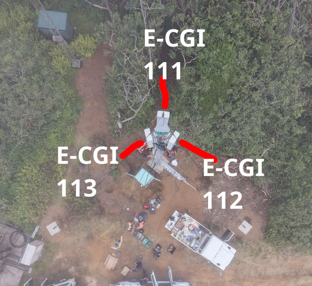
Every cell site sector (cell) has a unique ID to denote which carrier you’re connected to. If you’ve got a 3 sector site, with a single layer per cell sector, then that’s 3 Cell Global Identifiers (CGIs) – one for each sector.
Here’s a tower we put up recently, the CGIs I’ve drawn on are just examples, but if you’re connected to the sector facing North, you’d have CGI of 111, if you’re connected to the cell to the south east, you’d have 112, and the one to the south west would be 113.
CGIs are just numbers, they could be any number, all that matters is that number is unique (ish) in the network, they don’t need to be sequential, or have any common digits.
If we know the CGI of a given user we can kinda draw a 1/3rd wedge off the side of the tower in the direction the antenna is pointing, and if you’re inside that wedge, and that tower is still providing coverage, then we know the customer is somewhere inside that wedge.
But those wedges can still be large, so the margin of error for locating someone is still pretty large. You can probably answer the question of “Are they in the office or are they at home” if they’re in different suburbs.
When the network wants to know a bit more about where the phone is located, it can ask the cell site which Global Cell ID the phone is in, this is pretty rare, but can be done. When the phone is actively doing stuff, like making a call, using data or sending a text, the network knows the CGI of the event.
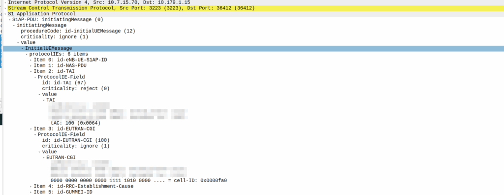
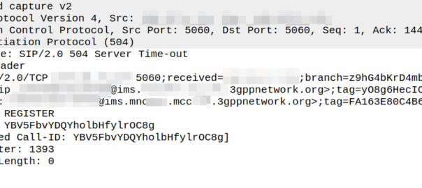
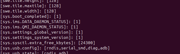
My lab is setup with CGI 4000 and TAC 100, and this information is littered across every signaling message.
Initial Attach message
Note: The encoding shows up as 0000 0000 0000 0000 1111 1010 0000 …. = cell-ID: 0x0000fa0 for CGI 4000, just roll with it, the spec explains why this is.
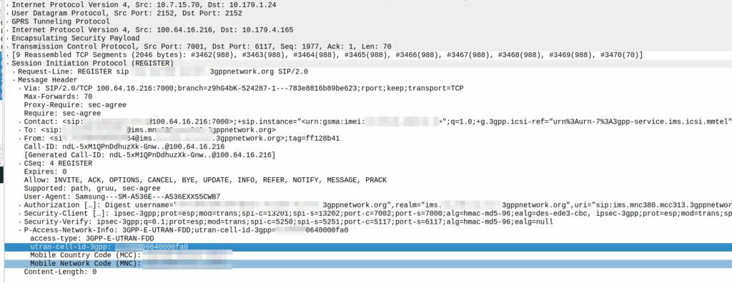
A SIP REGISTER message from my lab, showing the CGI (00640000fa0)
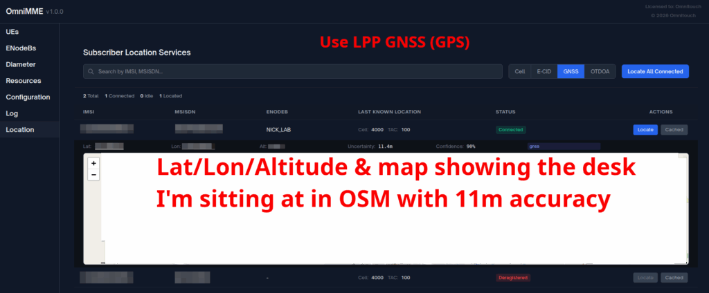
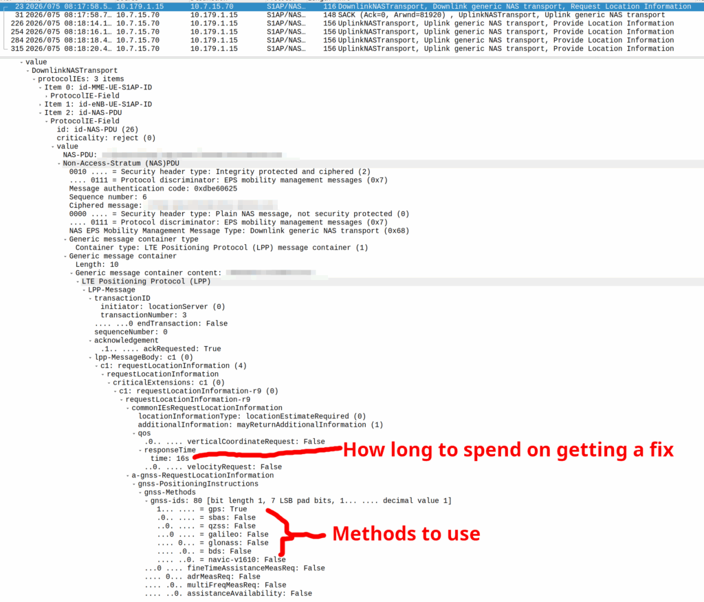
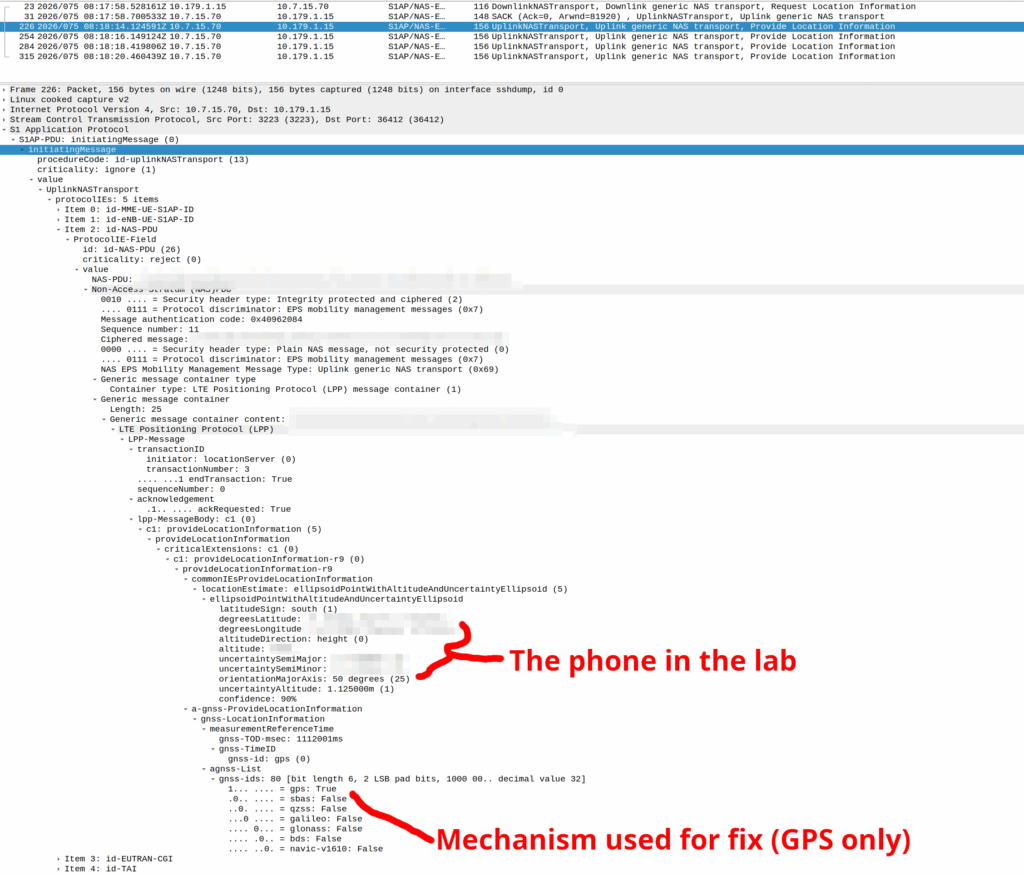
GNSS LPP Positioning
When the Cell ID level is not accurate enough, the network can request the phone to provide it’s location, using whatever it’s got available to it.
In reality, this is either done by an engineer from the phone company with the permissions to do so, or directly by law enforcement using the SLh/SLg Diameter interfaces.
When an engineer does it, there’s usually a portal they can go to, like this one in OmniMME, they search the IMSI or MSISDN, and then can get the location information via a variety of methods.
Your phone gets a message from the network, that says “Hey phone, tell me where you are”.
If you’ve got enough access to the baseband you can even block these requests should you feel so inclined.
I’ve included some Wireshark captures of how this actually looks and how it looks from the Web UI of the MME, with the address removed.
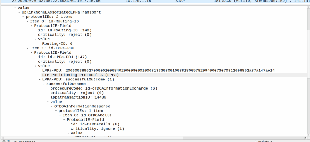
OTDOA – “Pinging”
Sometimes you don’t get an indoor location with GPS or the phone might be too old to support LPP Positioning, no GPS built in or something.
In those scenarios, we use “Time Difference of Arrival” to calculate the position by measuring time between 2 or more cell sites, and calculating the time between when a signal was sent to a phone, and when it receives it, to calculate distance from the base station.
This is better than CGI as it gives you an idea of how far from the cell site the phone is, and the cell site, but it doesn’t return a map with “you are here”, but rather some rough distances, and CGIs for each cell it can see.
The engineer then pulls up a map of all the cell sites, finds the CGIs the cell phone can see, headings for each CGI and tries to do some early high school maths like someones life actually depends on it.
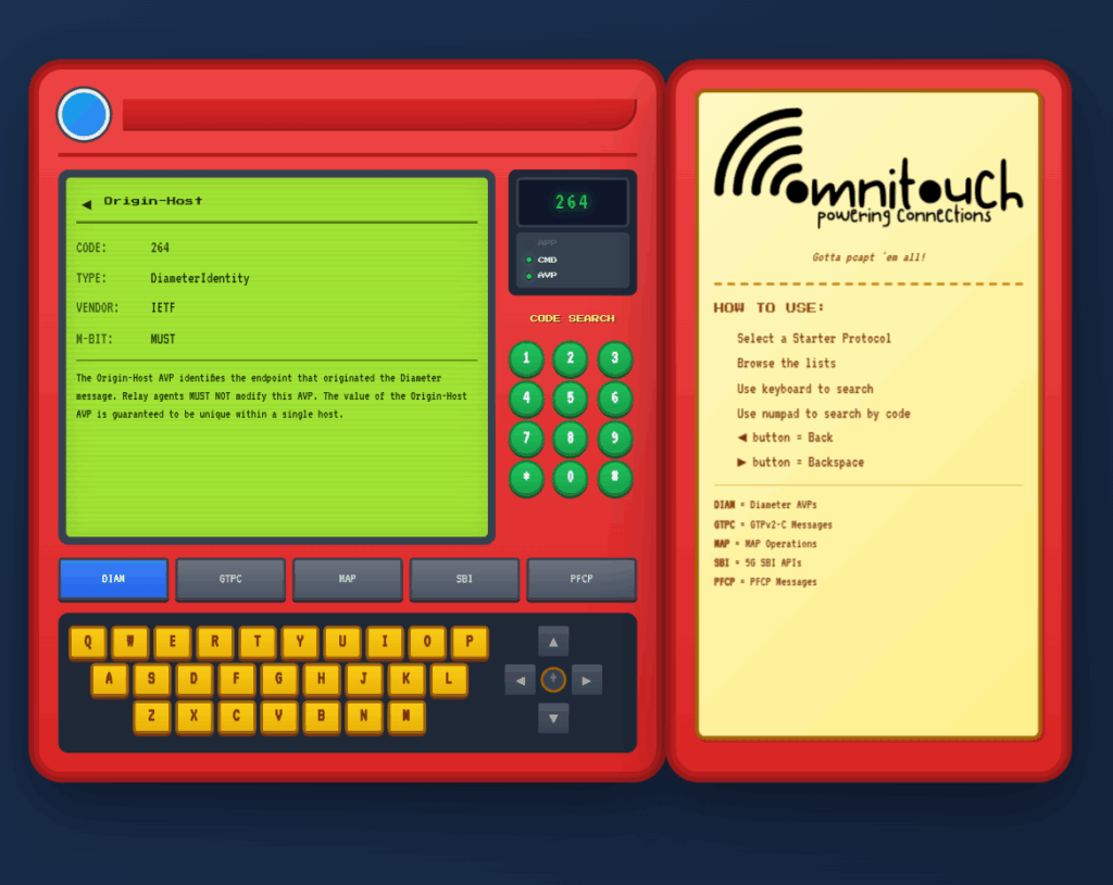
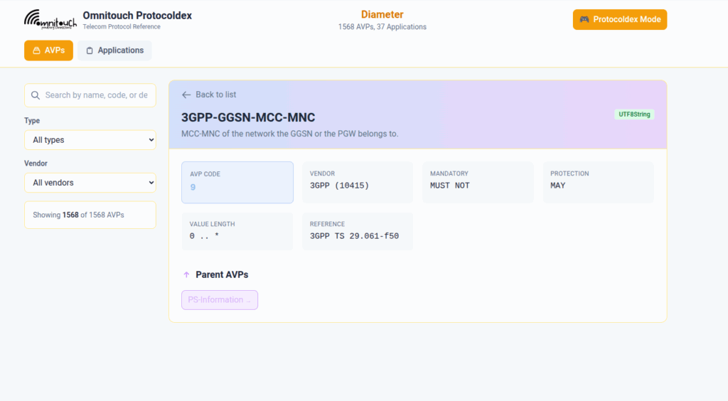
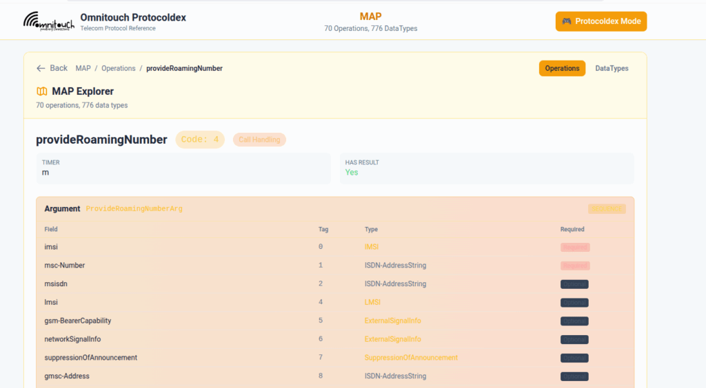
I do a lot of protocol testing, writing Diameter/PFCP/GTP-C etc, and spend a lot of time referencing the standards.
So I built this – Inspired by a 1990s video game / TV / Playing card franchise online reference tool, but rather than identifying pocket monsters, it’s identifying AVPs and stuff
You can punch in the AVP code, AVP name, description, etc, for Diameter, PFCP, GTP-C, MAP or SBI and see all the details to go with it.
I’ve been using it a heap, hopefully some of you might find it useful:
When a UE enters Idle mode, the network releases radio resources and the UE enters power saving mode.
When the UE wants to send data (Uplink) the UE just tells the network “hey I want to send something” and away it goes, nice and simple.
But when the network wants to send data to the UE (Downlink) then the UPF needs a method to tell the Control Plane (SGW-C or SMF) that there’s data waiting and to go and page the UE.
A prime example of this is when you’ve got a Mobile Terminated VoLTE call coming in, you need a way to tell the UE to wake up out of Idle mode because you’ve got something to send to it (a SIP INVITE).
But in order for this to work, we can’t just say “Hey I’ve got some packets for you” and let them get dropped, the UPF also needs to buffer (store temporarily) the downlink packets for the UE until the UE comes out of Idle mode, and then flush them out to deliver them to the UE.
So let’s look at the flow.
Enabling Buffering (Idle Mode)
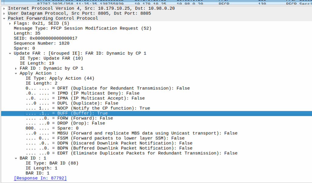
When the sub enters idle mode, the Control Plane (SGW-C for an EPC or SMF for a 5GC) it sends a Session Modification Request but with the BUFF (Buffer) and NOCP (Notify Control Plane) flags set, and FORW (Forward) turned off.
What this means is now for packets to that bearer, the UPF must:
Not forward any traffic
Buffer the traffic
Notify the control plane when the first packet comes in that we buffer
Then the UPF just sits and waits for any incoming packets.
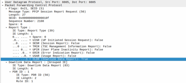
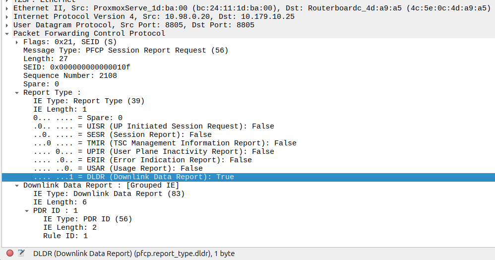
The Notify
When the UE gets an incoming packet that it’s supposed to buffer and notify, well, it does just that.
The packets are copied into a buffer, in sequence, and for the first packet, the UPF must send a notification to the Control Plane.
That looks like this, it’s just a Session Report Request with the Dowlink Data Report flag.
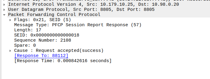
Now the SMF/SGW-U sends back a Session Report Response and starts the process of paging the UE.
At the same time the UPF keeps buffering – It’s work is not done.
Flushing and Forwarding
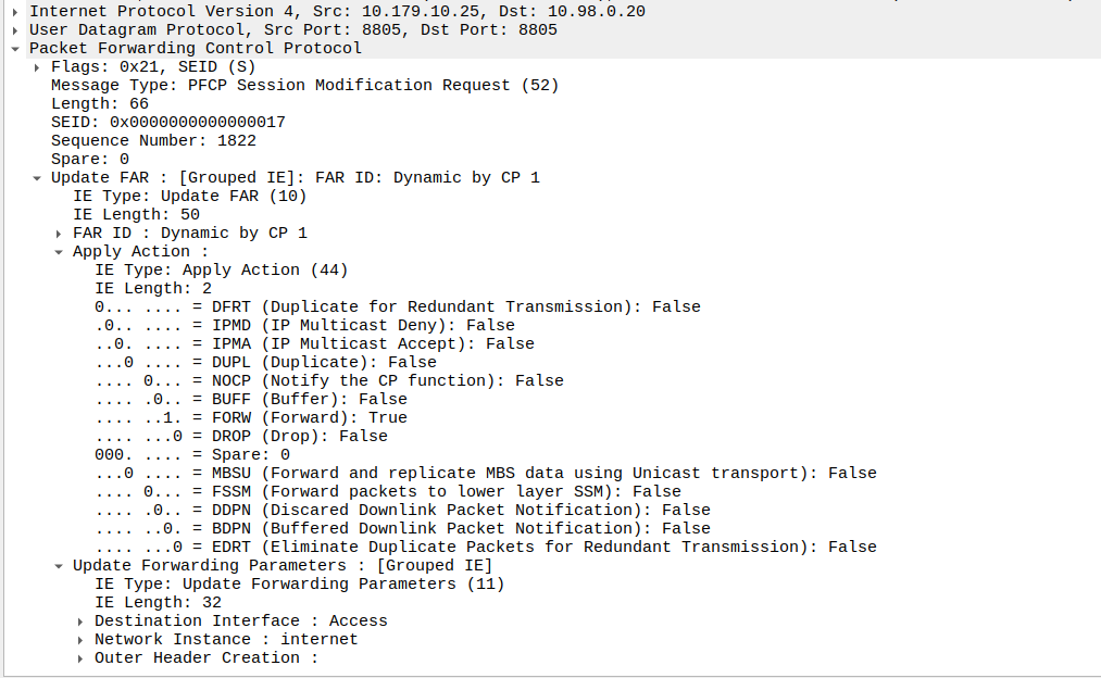
Once the UE has become reachable, the Control Panel needs to modify the bearer to turn back on forwarding. It does through another Session Modification Request, this is the inverse of the one it sent to turn on buffering, as we’re turning off buffering and notifications, and turning on forwarding.
Now the UPF flushes it’s buffer – It’ll send all the packets that were queued up out over the wire towards the gNB / eNodeB, so the SIP INVITE for the MT call or whatever will make it through.
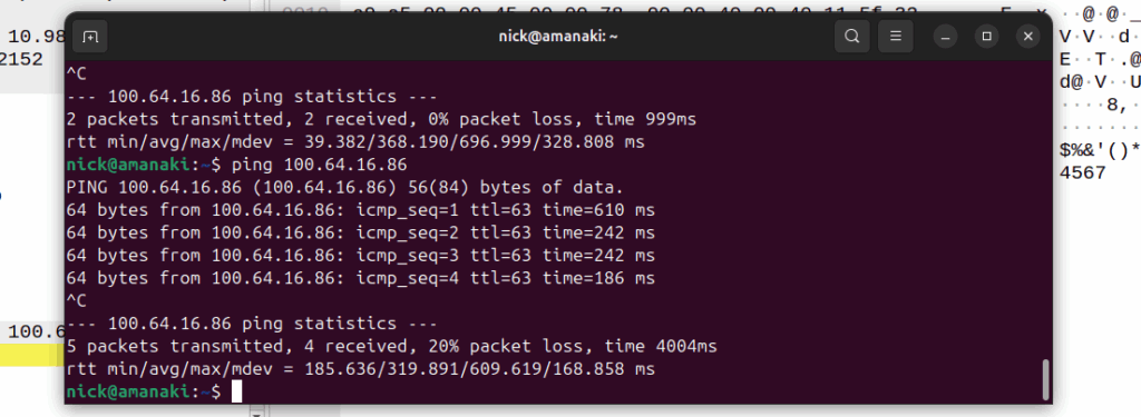
One thing to note is that the packets that get buffered are going to take some time to get delivered, as the NOTIFY / page UE / reconnect UE / Session Modification Request (to enable forwarding again) needs to happen before the buffers are flushed and delivered.
Notice the latency spike on the first packet? 610ms? That’s because the UE had to be paged to wake up.
And that’s pretty much it, the UPF has now flushed it’s buffers and moves back to forwarding actions.
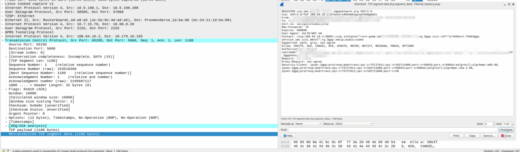
Our team recently shipped a new UPF which is a huge improvement on our old UPF, and I drew the short straw of doing all the interop testing for the IMS.
Initially I thought there was an issue with IP routing, as I’d never see the SIP register from the UE, but I would see the IMS APN coming up.
I could access the internet from the UE IPs just fine, but that’s going to public IPs, whereas the P-CSCF is in private address space, and hosted on the same box as the UPF.
I spent hours on this as my lab servers do routing on a stick, and I thought some hardware offload somewhere was trying to fast path my packets and send them back to the server without going via the router.
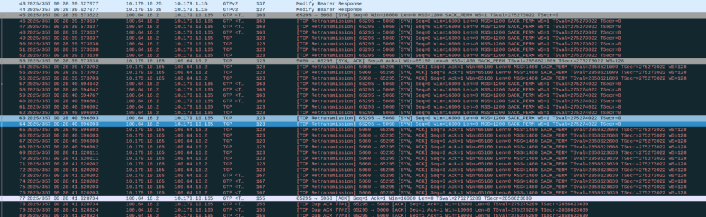
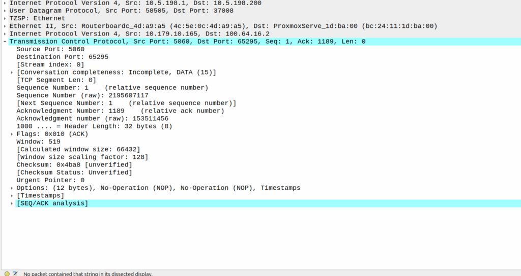
Then I dug a little deeper and found I could see the 3 way handhake between the UE an the P-CSCF, but no SIP packets.
Successful 3 way handshake between the UE and the P-CSCF on TCP 5060
This was confusing, clearly we had at least intermittent two way comms – the 3 way TCP handshake confirmed that, but then why were packets not getting across?
We have an XCAP server hosted on our P-CSCF instances, so I tried hitting that from the phone in case there was something weird about routing to the network segment that hosts the P-CSCF, but I could hit the XCAP server just fine, so now I was certain the UE IP pool could route to the P-CSCF and 3 way handshake for TCP was working and payload could be pushed.
Clearly we can route to the P-CSCF as that’s where this XCAP server is hosted
Then I dug into what happened after the 3 way handshake, and I found a TCP payload containing the start of the SIP REGISTER.
Hmm, we have a SIP Fragment here at least…
I traced it all the way through and lo, it’s hitting the P-CSCF:
And the fragment is recieved on the P-CSCF
Okay, but then what happens, because it’s only a fragment, not the complete re-assembled packet, so what’s going on?
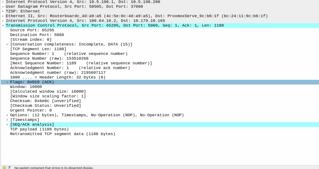
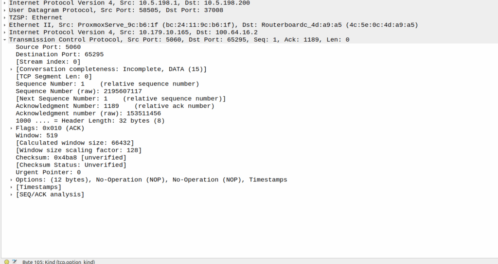
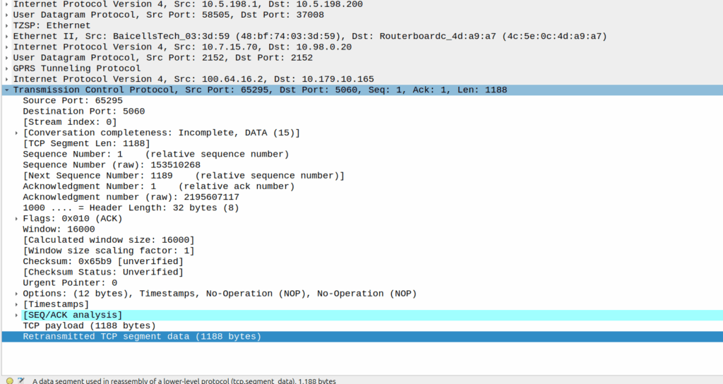
Well, the P-CSCF sends a TCP ACK back to the UE.
And the TCP fragment containing the first part of the REGISTER gets an ACK back from the P-CSCF
The ACK gets forwarded to the UPF:
And that TCP ack makes it to the P-CSCF
And then… Nothing? The UPF never encaps the TCP ACK back into GTP-U and never sends it onto base station.
Eventually the UE re-sends the payload with the start of the REGISTER, but it does not get the ACK from the P-CSCF.
Retransmitted TCP segment containing the REGISTER from the UE
So naughty UPF right? Not forwarding that ACK for some reason?
I started digging, maybe the ACK was getting routed weirdly and landing on the UPF without going through the router?
Well not quite…
When I started digging into the QER rules being installed I noticed the MBR bitrate we had on the IMS APN in the HSS was tiny.
The UPF can only gate on traffic to the UE, so was gating the ACK traffic, as the QER had consumed all the bandwidth so the ACK never made it back.
Time wasted – About 4 hours, but I will not make this mistake again!
A concept that’s always been a bit unclear to me was how the Sh Profile, XCAP data for call forwarding / barring and RepositoryData all fit together.
Let’s start off with the basics.
The Diameter Sh interface sits between an Application Server (Typically TAS, SMSc, XCAP server, etc) and the HSS.
This AS can run a Diameter User Data Request to get the contents of Sh Data, which is returned in the User Data AVP (702) for a given subscriber.
Application Servers can also subscribe to be notified of changes in the Sh data on the HSS, by sending a Subscriber Notification Request, and when the data changes they’ll get a “Push Notification Request” to inform them of the change.
When sending this User Data Request the AS can specify what data it wants to get returned, for example an AS might want to know the current S-CSCF of a given subscriber, in which case, the AS would set the DataReference AVP (703) to 12 for S-CSCFName.
Not the complete list…
The the AS can request can be public and private identities (IMSIs and MSISDNs), location in the PS and CS networks, TADS info, SRVCC parameters, etc, etc.
Data like TADS Info, CS and PS network location, Public and Private identities, come from the HSS and cannot be modified, these values either come from the static subscriber definition in the HSS (what was set when provisioning the subscriber), or based on the subscriber’s state (ie where they’re registered on the network).
RepositoryData
But there is a section of data we can request the HSS return called RepositoryData which can be modified/updated by the end user or other applications in the network (Modified by ASes), via a Profile Update Request.
This data is where we put the call forwarding, call barring, caller ID presentation/restriction info – The HSS doesn’t really care what is stored in RepositoryData, it’s just a transparent place to store this data.
Think of it as a simple folder containing text files, each text file has a name (ServiceNotification) which allows us to reference the blobs of data by name, a SequenceNumber to identify duplicates, and then the actual contents of the file itself ServiceData.
We can then request the contents of these files from the HSS by calling DataReference of RepositoryData and setting the ServiceIndication to be the “file” we want returned to the AS by the HSS.
For example, if the Data-Reference AVP is set to zero (Repository Data) and the Service-Indicator AVP is set to “IMS-ODB-Information” the HSS will return the data for the file IMS-ODB-Information of repository data.
This RepositoryData is just “transparent” storage of XML data by the HSS, and this is where we’d put Call Forwarding, Operator Defined Barring and CLI presentation/restriction parameters.
In theory you could also store 3rd party custom unstructured data here (Move over AWS S3 buckets, I’m moving all my storage to Diameter!), but it’s not commonly used beyond call routing parameters.
The two most common types of ServiceIndication keys you’ll see stored in RepositoryData are MMTEL-Services and IMS-ODB-Information. Each of these are defined by their own XML spec, but the MMTel-Services key is where all of our Call Forwarding, Caller ID Presentation/Restriction parameters live, while IMS-ODB-Information contains the parameters for Operator Defined barring – Both of these XML definitions we’ll dive into in a post of their own, but for now all you need to remember is that they’re stored transparently as XML on the HSS.
An example use case of this would be when a user wants to manage their call forwarding data via XCAP. When the user pulls up the Call Forwarding menu on their phone, the first entry point will be the XCAP Server (AS) to get all the User Data for MMTelServices, so it’ll do that via a Diameter User Data Request with the DataReference set to RepositoryData and the ServiceIndication set to MMTel-Service so the XCAP server can pass the full XCAP XML body to the UE.
The UE can then update this data, and the XCAP server just sends a Profile Update Request to push the updated XML to be stored on the HSS.
Fitting this all Together
Data sent to the AS by the HSS will always include the <Sh-Data> XML, but the child keys within it depend on the data the AS requested under the Data-Reference.
If we requested IMSI as the DataReference, then the returned XML might look like:
<Sh-Data>
 <imsi>9990112345677</imsi>
</Sh-Data>
Likewise, if you requested IMSPublicIdentity as the DataReference you’d get:
The spec goes into full detail on all the possible keys, but in short, when the AS queries the data for the provided DataReference, the HSS sends back an Sh-Data XML body containing at a minimum those keys.
Recently we ran into an issue with certain devices while roaming not including an ICSCI field in the Contact header while registering onto the IMS, leading to MT call failures.
So what is ICSI and why were these calls failing?
The IMS standards are littered with novel ideas for smart telephony features that no one ever implimented, and presents a minefield of conditionals about features you never even knew existed.
Today’s dead feature is the “IMS Communication Service Identifier” (ICSI), no, it’s not a TV show about IMS Crime Scene Investigators (don’t steal my pitch), instead ICSI identifies IMS services by using “IMS Enablers” which allows multiple IMS applications to run on the phone.
It’s like a VLAN or a VRF but for IMS, one IMS stack but multiple sub-IMS stacks I guess.
Why would you want to do this you might ask? Well, the example from the Specs is if you were using OMA’s very short lived OMA Instant Messaging and Presence application, which uses SIP for transport, but needs the SIP messages routed to the OMA client application in the phone, rather than the standard IMS SIP client in the phone for making calls / texts.
Alternately, you could have a mobile PBX application for office workers, and with a different ICSI this could use a secondary dialler with a contacts list and presence for all your co-workers, these sorts of “sub” IMS clients and applications were possible with ICSI.
So how does it actually work? Well, it’s stupid simple, during register the phone indicates in the Contact header what ICSI applications that client supports.
When a call is made by the UE based on this value the iFCs can route to different Application Servers based on the values.
For mobile originated calls, the terminal in this scenario is kinda meant to work like a SIP Proxy, dispatching a SIP message to the correct application (in the terminal another IMS client that spoke to the main phone).
In reality though, there is only one ICSI service seen in 99.999% of IMS traffic and that’s the 3gpp-service.ims.icsi.mmtel ICSI, used by IMS clients to denote that they support IMS Multimedia Telephony, aka just normal IMS.
For reasons best know to VENDOR X (you know who you are) their phones include the 3gpp-service.ims.icsi.mmtel in the Contact header when registering on the home network, but while registering while roaming do not include this.
Our TAS ignores the lack of ICSI for mmtel in the contact on regular MT calls, but one of the other TAS vendors in the mix got grumpy because it was missing, and they didn’t have a contact for MMtel for the registered subscriber.
In the end we rewrote the headeron on our CSCFs before passing it to their TAS, which resolved the issue.
Who’s in the wrong? Well, the particular phone vendor who doesn’t include MMtel in the ICSI Contact, but that’s not going to change any time soon. So as the old saying goes, if the mountain won’t come to Mohammed… Mohammed will rewrite SIP headers.
We were testing international roaming for a customer, roaming into the US where one of our team members (shoutout to Cody) is based.
So we sent Cody some SIMs and asked them to run the basic tests for us, but no IMS APN would attach.
We’d get them to power up the phone, fire up a trace on the roaming PGWs, but never seeing an attempt to attach on the IMS APN (No Create Session Request from the SGW in the vPMN).
The operator we were roaming into swore their side was correct – that IMSI was allowed for the IMS APN for testing, but whenever we’d run a trace, same thing, default bearer just fine but no CSR for the IMS APN, as if the IMS APN was blocked on the roaming network (Which is common on networks where you haven’t launched VoLTE but do have data roaming).
The steps we would do is:
Person in the US turns on phone tries to attach
I fire up my computer, get a trace running
Person in the US airplanes the device
I monitor for CSRs on the PGWs for that IMSI
But no CSR for the IMS APN would ever come through.
After a few attempts, here’s what we found was happening:
The phone would get powered up
The phone would roam onto the vPMN in the US and the default bearer would come up
The phone would try to attach to the ims APN, this would work for this SIM which was whitelisted, and the Create Session Request for the ims APN went to the PGW in the hPMN
The ims APN came up as expected
The phone would send a SIP REGISTER (So far so good)
Our IMS had an issue with Rx routing in this scenario, so the SIP REGISTER would timeout, and when it timed out, a 504 error was sent back to the phone by the P-CSCF and it set the Retry-After header to 3600 seconds.
The phone would not try again for as long as that timer value was set.
At this point we’d start a trace, airplane the device, and see no IMS APN attach attempt.
This 504 Timeout would all happen when the phone fired up before we had any traces running, so we weren’t capturing that.
I’d wrongly assumed that airplaning the device after starting a trace would reset the state fully, but it doesn’t, neither does a restart of the phone.
When we’d started a trace and airplane the phone, the phone wouldn’t try to attach to the ims APN as it was still inside the Retry-After time window from when we’d first fired it up.
Per RFC 3261, the phone should not try again during this time, which in our case meant no attempt to attach to the IMS APN, this makes sense – it protects the network against the thundering herd problem, but made this otherwise simple fault really hard to find.
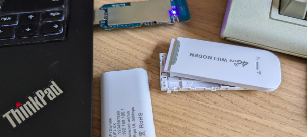
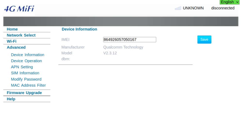
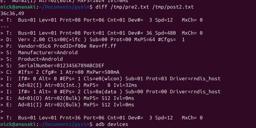
The device showed up as an rndis_host adapter in Linux, just like a USB NIC, and browsing to the default gateway shows a web UI where amazingly, you can set the IMEI – Pretty sure this isn’t legal…
This is not the IMEI it came with – that’s the IMEI of a EP06-e chip on my desk…
Oddly I could see it was an Android device, but with no adb port exposed, but wait – does that mean this an Android phone in a USB stick?
Alas no DIAG mode serial adapter showed up, despite a few variations on the above.
So with ADB connected could I stream the video from the device and use it like an Android phone?
You betcha:
After poking around in Android I found an App called “Qualcomm Settings” which piqued my interest.
Alas the unit only supports LTE Band 1 / 3 / 5 none of which I have in my office (I’m too lazy to go out to the lab to fire up an Airscale) so I put a public SIM in it and was able to use data, but when I tried to make a call it seems it kicked off CS fallback.
More exploring to do, but pretty amazing what $10 buys you!
Another post in the “vendors thought Java would last forever but the web would just a fad” series, this one on getting Nokia BTS Site Manager (which is used to administer the pre-Airscale Nokia base stations) running on a modern Linux distro.
For starters we get the installers (you’ll need to get these from Nokia), and install openjdk-8-jre using whichever package manager your distro supports.
Once that’s installed, then extract the installer folder (Like BTS Site Manager FL18_BTSSM_0000_000434_000000-20250323T000206Z-001.zip).
Inside the extracted folder we’ve got a path like:
BTS Site Manager FL18_BTSSM_0000_000434_000000-20250323T000206Z-001/BTS Site Manager FL18_BTSSM_0000_000434_000000/C_Element/SE_UICA/Setup
The Setup folder contains a bunch of binaries.
We make these executable:
chmod +x BTSSiteEM-FL18-0000_000434_000000*
Then run the binary:
sudo ./BTSSiteEM-FL18-0000_000434_000000_x64.bin
By default it installs to /opt/Nokia/Managers/BTS\ Site/BTS\ Site\ Manager
And we’re done. Your OS may or may not have built a link to the app in your “start menu” / launcher.
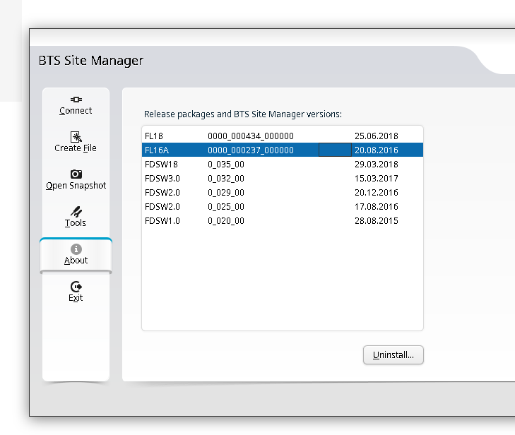
You can use one BTS manager to manage several different versions of software, but you need the definitions for those software loaded.
If you want to load the Releases for other versions (Like other FLF or FL releases) the simplest way is just to install the BTS site manager for those versions and just use the latest, then you’ll get the table of installed versions in the “About” section that you can administer.
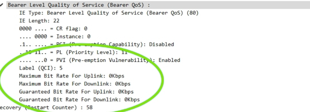
The other day I had a query about a roaming network that was sending Bearer Level QoS parameters in the Create Session Request to 0Kbps, up and down rather than populating the MBR values.
I knew for Guaranteed Bit Rate bearers that this was of course set, but for non GBR bearers (QCI 5 to 9) I figured this would be set the to MBR, but that’s not the case.
So what gives?
Well, according to TS 29.274:
For non-GBR bearers, both the UL/DL MBR and GBR should be set to zero.
So there you have it, if it’s not a QCI 1-4 bearer then these values are always 0.
Nope – it doesn’t do anything useful. So why is it there?
The SUBSCRIBE method in SIP allows a SIP UAC to subscribe to events, and then get NOTIFY messages when that event happens.
In a plain SIP scenario (RFC 3261), we can imagine an IP Phone and a PBX scenario. I might have “Busy Lamp Field” aka BLF buttons on the screen of my phone, that change colour when the people I call often are themselves on calls or on DND, so I know not to transfer calls to them – This is often called the “presence” scenario as it allows us to monitor the presence of another user.
At a SIP level, this is done by sending a SUBSCRIBE to the PBX with the information about what I’m interested in being told about (State changes for specific users) and then the PBX will send NOTIFY messages when the state changes.
But in IMS you’ll see SUBSCRIBE messages every time the subscriber registers, so what are they subscribing for?
Well, you’re just subscribing to your own registration status, but your phone knows your own registration status, because it’s, well, the registration status of the phone.
So what does it achieve? Nothing.
The idea was in a fixed-mobile-convergence scenario (keeping in mind that’s one of the key goals from the 2008 IMS spec) you could have the BLF / presence functionality for fixed subscribers, but this rareley happens.
For the past few years we’ve just been sending a 200 OK to SUBSCRIBE messages to the IMS, with a super long expiry, just to avoid wasting clock cycles.
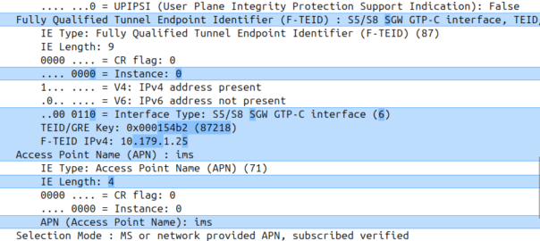
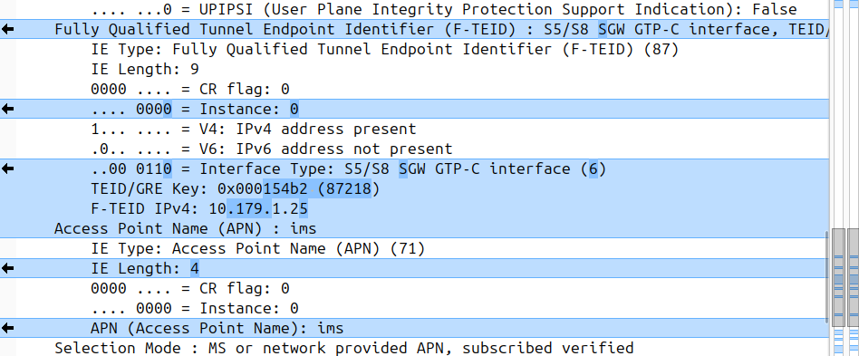
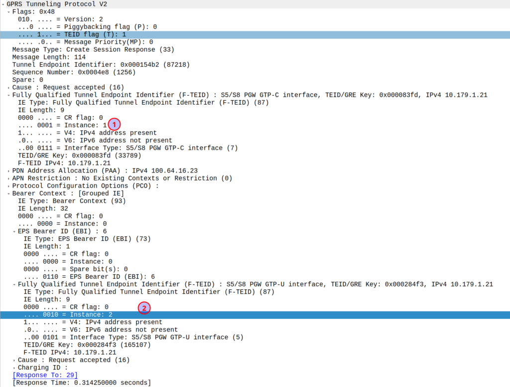
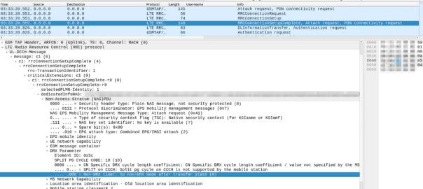
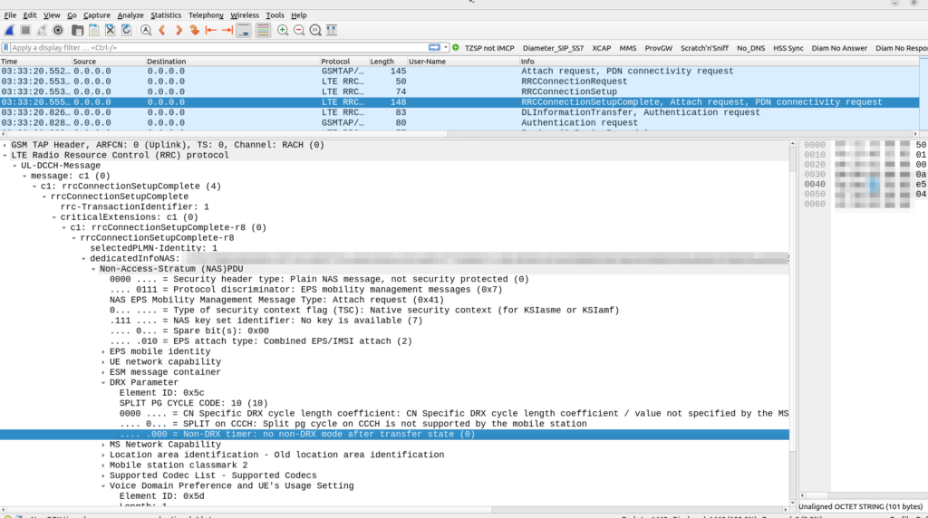
I was diffing two PCAPs the other day trying to work out what’s up, and noticed the Instance ID on a GTPv2 IE was different between the working and failing examples.
If more than one grouped information elements of the same type, but for a different purpose are sent with a message,
these IEs shall have different Instance values.
So if we’ve got two IEs of the same IE type (As we often do; F-TEIDs with IE Type 87 may have multiple instances in the same message each with different F-TEID interface types), then we differentiate between them by Instance ID.
The only exception to this rule is where we’ve got the same data, so if you’ve got one IE with the exact same values and purpose that exists twice inside the message.
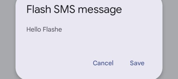
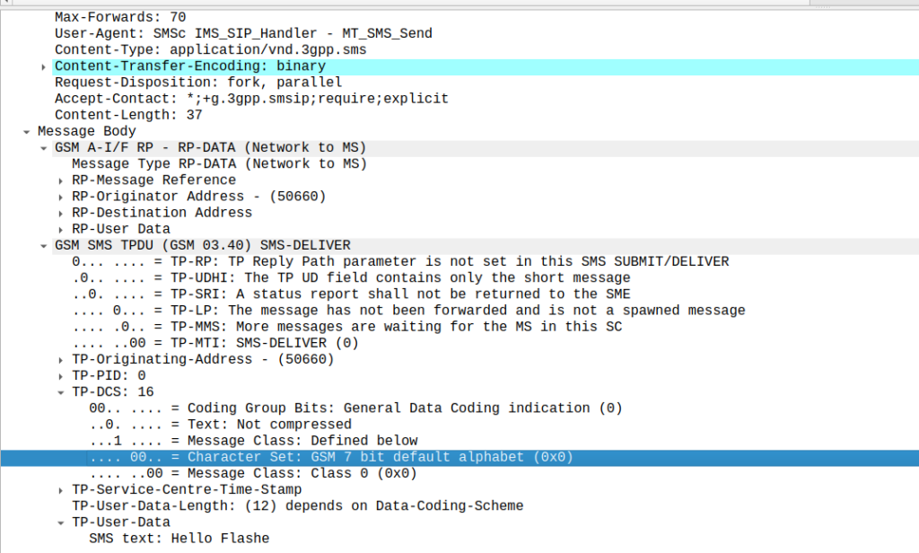
Stumbled across these the other day, while messing around with some values on our SMSc.
Setting the Data Coding Scheme to 16 with GSM7 encoding flags the SMS as “Flash message”, which means it pops up on the screen of the phone on top of whatever the user is doing.
While reading a quality telecom blog bam! There’s the flash SMS popping over whatever I was reading.
Oddly while there’s plenty of info online about Flash SMS, it does not appear in the 3GPP specifications for SMS.
Turns out they still work, move over RCS and A2P, it’s all about Flash messages!
There’s no real secret to this other than to set the Data Coding Scheme to 16, which is GSM7 with Flash class set. That’s it.
Obviously to take advantage of this you’d need to be a network operator, or have access to the network you wish to deliver to. Recently more A2P providers are filtering non vanilla SMS traffic to filter out stuff like SMS OTA message or SIM specific messages, so there’s a good chance this may not work through A2P providers.
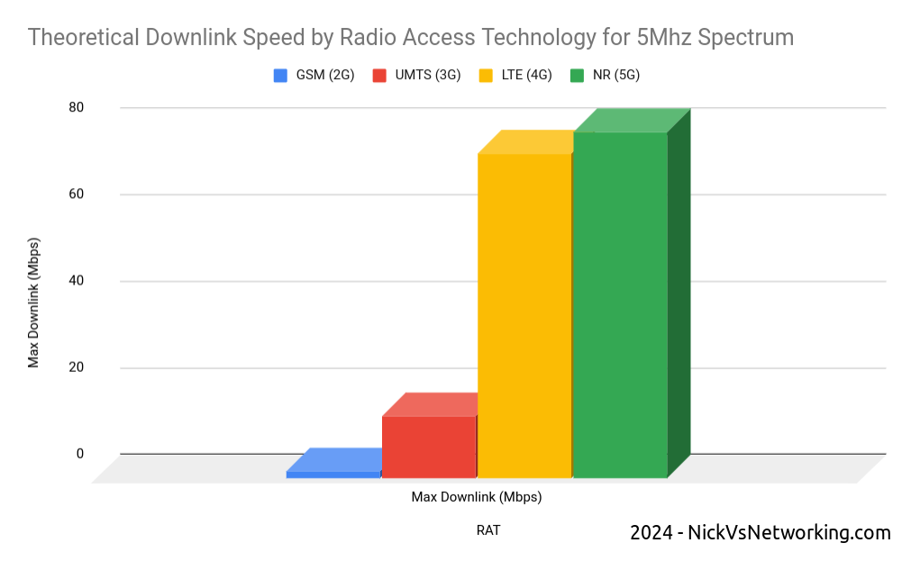
I’ve been writing a fair bit recently about the “VoLTE Mess” – It’s something that’s been around for a long time, mostly impacting greenfield players rolling out LTE only, but now the big carriers are starting to feel it as they shut off their 2G and 3G networks, so I figured a brief history was in order to understand how we got here.
Note: I use the terms 4G or LTE interchangeably
The Introduction of LTE
LTE (4G) is more “spectrally efficient” than the technologies that came before it. In simple terms, 1 “chunk” of spectrum will get you more speed (capacity) on LTE than the same size chunk of spectrum would on 2G or 3G.
So imagine it’s 2008 and you’re the CTO of a mobile network operator. Your network is congested thanks to carrying more data traffic than it was ever designed for (the first iPhone had launched the year before) and the network is struggling under the weight of all this new data traffic. You have two options here, to build more cell sites for more density (very expensive) or buy more spectrum (extremely expensive) – Both options see you going cap in hand to the finance team and asking for eye-wateringly large amounts of capital for either option.
But then the answer to your prayers arrives in the form of 3GPP’s Release 8 specification with the introduction of LTE. Now by taking some 2G or 3G spectrum, and by using it on 4G, you can get ~5x more capacity from the same spectrum. So just by changing spectrum you own from 2G or 3G to 4G, you’ve got 5x more capacity. Hallelujah!
So you go to Nortel and buy a packet core, and Alcatel and Siemens provide 4G RAN (eNodeBs) which you selectively deploy on the cell sites that are the most congested. The finance team and the board are happy and your marketing team runs amok with claims of 4G data speeds. You’ve dodged the crisis, phew.
This is the path that all established mobile operators took; throw LTE at the congested cell sites, to cheaply and easily free up capacity, and as the natural hardware replacement cycle kicked in, or cell sites reached capacity, swap out the hardware to kit that supports LTE in addition to the 2G and 3G tech.
Circuit Switched Fallback
But it’s hard to talk about the machinations of late 2000s telecom executives, without at least mentioning Hitler.
This video below from 15 years ago is pretty obscure and fairly technical, but the crux of it it is that Hitler is livid because LTE does not have a “CS Domain” aka circuit switched voice (the way 2G and 3G had handled voice calls).
It was optional to include support for voice calls in the LTE network (Voice over LTE) when you launched LTE services. So if you already had a 2G or 3G network (CS Network) you could just keep using 2G and 3G for your voice calls, while getting that sweet capacity relief.
So our hypothetical CTO, strapped for cash and data capacity, just didn’t bother to support VoLTE when they launched LTE – Doing so would have taken more time to launch, during which time the capacity problem would become worse, so “don’t worry about VoLTE for now” was the mantra.
All the operators who still had 2G and 3G networks, opted to just “Fallback” to using the 2G / 3G network for calling. This is called “Circuit Switched Fallback” aka CSFB.
Operators loved this as they got the capacity relief provided by shifting to 4G/LTE (more capacity in the network is always good) and could all rant about how their network was the fastest and had 4G first, this however was what could be described as a “Foot gun” – Something you can shoot yourself in the foot with in the future.
Operators eventually introduce VoLTE
Time ticked on an operators built out their 4G networks, and many in the past 10 years or so have launched VoLTE in their own networks.
For phones that support it, in areas with blanket 4G coverage, they can use VoLTE for all their calls.
But that’s the sticking point right there – If the phones support it.
But if the phones don’t support it, they’re roaming or making emergency calls, there is always been the safety blanket of 2G or 3G and Circuit Switched fallback to well, fall back to.
There’s no driver for operators who plan to (or are required to) operate a 2G or 3G network for the foreseeable future, to ensure a high level of VoLTE support in their devices.
For an operator today with 2G or 3G, Voice over LTE is still optional. Many operators still rely exclusively on Circuit Switched Fallback, and there are only a handful of countries that have turned off 2G and 3G and rely solely on VoLTE.
VoLTE Handset Support
For the past 16 years phone manufacturers have been making LTE capable phones.
But that does not mean they’ve been making phones that support Voice over LTE.
But it’s never been an issue up until this point, as there’s always been a circuit switched (2G/3G) network to fall back to, so the fact that these chips may not support VoLTE was not a big problem.
Many of the cheaper chipsets that power phones simply don’t support VoLTE – These chips do support LTE for data connections but rely on Circuit Switched Fallback for voice calls. This is in part due to the increased complexity, but also because some of the technologies for VoLTE (like AMR) required intellectual property deals to licence to use, so would add to the component cost to manufacture, and in the chips game, keeping down component cost is critical.
Even for chips that do support Voice over LTE, it’s “special”. Unlike calling in 2G or 3G that worked the same for every operator, phone manufacturers require a “Carrier Bundle” for each operator, containing that specific operators’ special flavor of VoLTE, that operator uses in their network.
This is because while VoLTE is standardized (Despite some claims to the contrary) a lot of “optional” bits have existed, and different operators built networks with subtle differences in the “flavor” of their Voice over LTE (IMS) stack they used. The OEMs (Phone / Chip manufacturers) had to handle these changes in the devices they made, for in order to sell their phones through that operator.
This means I can have a phone from vendor X that works with VoLTE on Network Y, but does not support VoLTE on Network Z.
Worse still, knowing which phones are supported is a bit of a guessing game.
Most operators sell phones directly to their customer base, so buying an Network Y branded phone from Vendor X, you know it’s going to support Network Y’s VoLTE settings, but if you change carriers, who knows if it’ll still support it?
When you’ve still got a Circuit Switched network it’s not the end of the world, you’ll just use CSFB and probably not realize it, until operators go to shut down 2G / 3G networks…
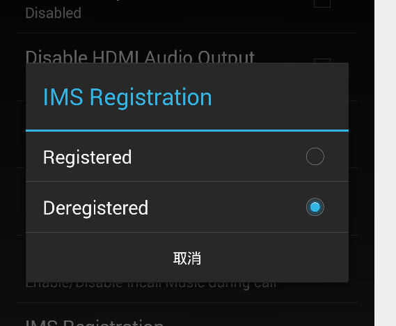
IMS Profile selection on an engineering mode MTK based Android handset
Navigating the Maze of VoLTE Compatibility
Here are some simple checklist you can ask your elderly family members if they ask if their phone is VoLTE compatible:
Does the underlying chipset the phone is based on support VoLTE? (you can find this out by disassembling the phone and checking the datasheets for the components from the OEMs after signing NDAs for each)
Does the underlying chipset require a “carrier bundle” of settings to have been loaded for this operator in order to support VoLTE (See Qualcomm MBM as an example)?
What version of this list am I currently on (generally set in the factory) and does it support this operator? (You can check by decapping the ICs and dumping their NVRAM and then running it through a decompiler)
Does my phones OS (Android / iOS) require a “carrier bundle” of it’s own to enable VoLTE? Is my operator in the version of the database on the phone? (See Android’s Carrier Database for example) (You can find the answer by rooting the phone and running some privileged commands to poke around the internal file system)
Does my operator / MNO support VoLTE – Does my plan / package support VoLTE? (You can easily find the answer by visiting the store and asking questions that don’t appear on the script)
If you managed to answer yes to all of the above, congratulations! You have conditional VoLTE support on your phone, although you probably don’t have a working phone anymore.
Wait, conditional VoLTE support?
That’s right folks, VoLTE will work in some scenarios with your operator!
If you plan on traveling, well your phone may support VoLTE at home, but does the phone have VoLTE roaming enabled? Many phones support VoLTE in the home network, but resort to CSFB when roaming.
If it does support VoLTE roaming, does the network you’re visiting support VoLTE roaming? Has the roaming agreement (IRA) between the operator you’re using while traveling and your home operator been updated to include VoLTE Roaming? These IRAs (AA.12 / AA.13 docs) also indicate if the network must turn off IPsec encryption for the VoLTE traffic when roaming, which is controlled by the phone anyway.
Phew, all this talk of VoLTE roaming while traveling scares me, I think I’ll stay home in the safety of the Australian bush with all these great friendly animals around a phone that supports VoLTE on my home network.
Ah – After spending some time in the Australian bush one of our many deadly animals bit me. Time to call for help! Wait, what about emergency calls over VoLTE? Again, many phones support VoLTE for normal calls, fall back to 2G or 3G for the emergency call, so if you have one of those phones (You’ll only find out if you try to make an emergency call and it fails) and try to make an emergency call in a country without 2G or 3G, you’d better find a payphone.
Sarcasm aside, there’s no dataset or compatibility matrix here – No simple way to see if your phone will work for VoLTE on a given operator, even if the underlying chip does support VoLTE.
Operators in Australia which recently shut down their 3G network, were mandated to block devices that didn’t support VoLTE for emergency calling. They did this using an Equipment Identity Register, and blocking devices based on the Type Allocation Code, but this scattergun approach just blocked non-carrier issued devices, regardless of it they supported VoLTE or VoLTE emergency calling.
Blame Game
So who’s to blame here?
There’s no one group to blame here, the industry has created a shitty cycle here:
Standards orgs for having too many “flavors” available
Operators deploying their own “Flavors” of VoLTE then mandating OEMs / Chip manufacturers comply with their “flavor”.
OEMs / Chip manufactures respond by adding “Carrier Bundles” to account for this per-operator customization
I’ve got some ideas on a way to unscramble this egg, and it’s going to take a push from the industry.
If you’re in the industry and keen to push for a fix, get in touch!
It’s time to get a long term solution to this problem, and we as an industry need to lead the change.
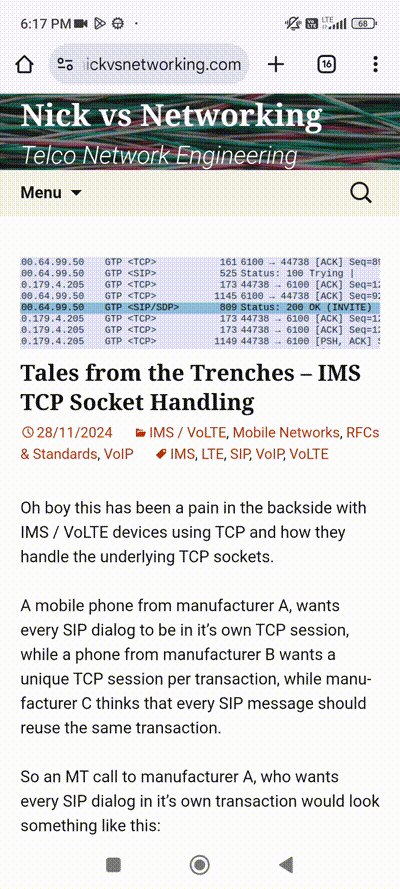
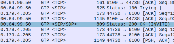
Oh boy this has been a pain in the backside with IMS / VoLTE devices using TCP and how they handle the underlying TCP sockets.
A mobile phone from manufacturer A, wants every SIP dialog to be in it’s own TCP session, while a phone from manufacturer B wants a unique TCP session per transaction, while manufacturer C thinks that every SIP message should reuse the same transaction.
So an MT call to manufacturer A, who wants every SIP dialog in it’s own transaction would look something like this:
PCSCF:44738 -> UE:5060; TCP SYN UE:5060 -> PCSCF:44738; TCP SYN/ACK PCSCF:44738 -> UE:5060; TCP ACK --- TCP connection is now open to UE from P-CSCF--- --- Start of new SIP Transaction 1 & Dialog --- PCSCF:44738 -> UE:5060; TCP PSH - SIP INVITE.... UE:5060 -> PCSCF:44738; TCP ACK
--- Start of SIP Transaction 2 --- PCSCF:44738 -> UE:5060; TCP PSH - SIP BYE.... UE:5060 -> PCSCF:44738; TCP ACK, PSH - SIP 200.... --- End of SIP Transaction 2 & SIP Dialog --- PCSCF:44738 -> UE:5060; TCP FIN UE:5060 -> PCSCF:44738; TCP ACK --- End of TCP Connection ---
Where UE:5060 – is the IP & port of the UE, as advertised in the Contact: header, while PCSCF:44738 is the PCSCF IP and a random TCP port used for this connection.
But for manufacturer B, who wants a unique TCP session per transaction, they want it to look like this:
PCSCF:44738 -> UE:5060; TCP SYN UE:5060 -> PCSCF:44738; TCP SYN/ACK PCSCF:44738 -> UE:5060; TCP ACK --- TCP connection is now open to UE from P-CSCF--- --- Start of new SIP Transaction 1 & Dialog --- PCSCF:44738 -> UE:5060; TCP PSH - SIP INVITE.... UE:5060 -> PCSCF:44738; TCP ACK
--- Start of TCP Session 2 ---- PCSCF:32627 -> UE:5060; TCP SYN UE:5060 -> PCSCF:32627; TCP SYN/ACK PCSCF:32627 -> UE:5060; TCP ACK --- Start of SIP Transaction 2 --- PCSCF:32627 -> UE:5060; TCP PSH - SIP BYE.... UE:5060 -> PCSCF:32627; TCP ACK, PSH - SIP 200.... --- End of SIP Transaction 2 & SIP Dialog --- PCSCF:32627 -> UE:5060; TCP FIN UE:5060 -> PCSCF:32627; TCP ACK --- End of TCP Connection 2 ---
And then manufacturer C wants just the one TCP session to be used for everything, so they open the TCP connection when they register, and that’s all we use for everything.
Is there any logic to this? Nope, seems to be tied to the underlying chipset (Qualcomm vs Mediatek vs Unisoc) and the SIP stack used (Qualcomm, MTK, Unisoc, Samsung, Apple).
We’ve profiled devices into one of 3 behaviors, and then we tag them based on user agent as to what “persona” they demand from the network.
I can’t believe I’m still talking about VoLTE / IMS handset support and it’s almost 2025…. For context IMS was “standardized” 17 years ago.
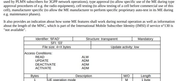
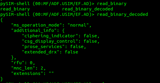
One of the guys at work asked a seemingly simple question, is the PLMN with MCC 505 and MNC 57 the same as MCC 505 MNC 057 – It’s on 6 octets after all.
So is Mobile Network Code 57 the same as Mobile Network Code 057 in the PLMN code?
The answer is no, and it’s a massive pain in the butt.
All countries use 3 digit Mobile Country Codes, so Australia, is 505. That part is easy.
The tricky part is that some countries (Like Australia) use 2 digit Mobile Network Codes, while others (Like the US) use 3 digit mobile network codes.
Why would you do this? Why would a regulator opt to have 1/10th the addressable size of network codes – I don’t know, and I haven’t been able to find an answer – If you know please drop a comment, I’d love to know.
That’s all well and good from a SIM perspective, but less useful for scenarios where you might be the Visited PLMN for example, and only see the IMSI of a Subscriber.
We worked on a project in a country that mixed both 2 digit and 3 digit Mobile Network Codes, under the same Mobile Country Code. Certain Qualcomm phones would do very very strange things, and it took us a long time and a lot of SIM OTA to resolve the issue, but that’s a story for another day…
Technology is constantly evolving, new research papers are published every day.
But recently I was shocked to discover I’d missed a critical development in communications, that upended Shannon’s “A mathematical theory of communication”.
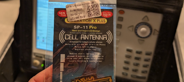
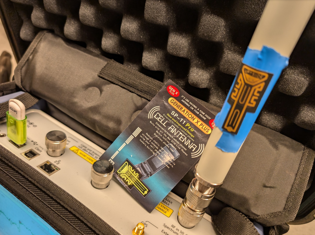
I’m talking of course, about the GENERATION X PLUS SP-11 PRO CELL ANTENNA.
I’ve been doing telecom work for a long time, while I mostly write here about Core & IMS, I am a licenced rigger, I’ve bolted a few things to towers and built my fair share of mobile coverage over the years, which is why I found this development so astounding.
With this, existing antennas can be extended, mobile phone antennas, walkie talkies and cordless phones can all benefit from the improvement of this small adhesive sticker, which is “Like having a four foot antenna on your phone”.
So for the bargain price of $32.95 (Or $2 on AliExpress) I secured myself this amazing technology and couldn’t wait to quantify it’s performance.
Think of the applications – We could put these stickers on 6 ft panel antennas and they’d become 10ft panels. This would have a huge effect on new site builds, minimize wind loading, less need for tower strengthening, more room for collocation on the towers due to smaller equipment footprint.
Luckily I have access to some fancy test equipment to really understand exactly how revolutionary this is.
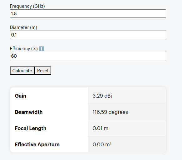
The packaging says it’s like having a 4 foot antenna on your phone, let’s do some very simple calculations, let’s assume the antenna in the phone is currently 10cm, and that with this it will improve to be 121cm (four feet).
Projected Gain (Post Sticker)Formulas Used
According to some basic projections we should see ~21dB gain by adding the sticker, that’s a 146x increase in performance!
Man am I excited to see this in action.
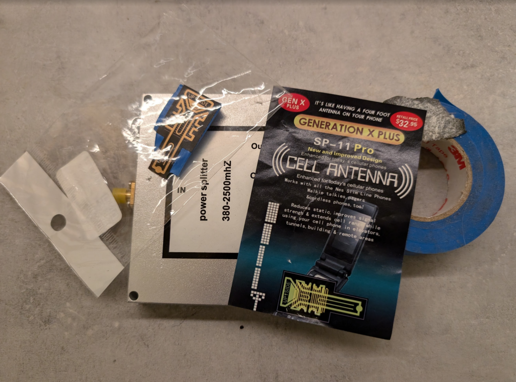
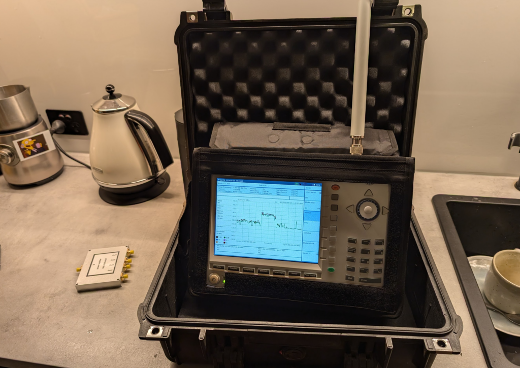
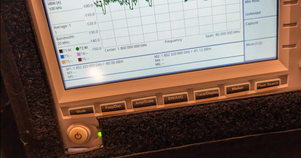
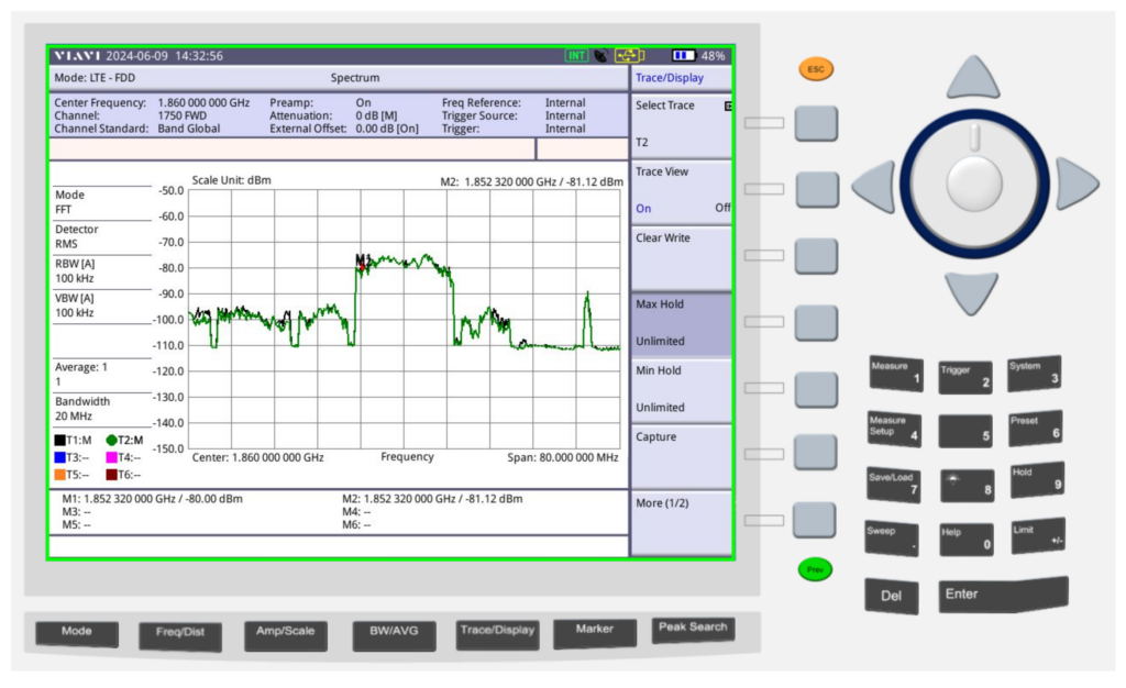
Fortunately I have access to some fun cellular test equipment, including the Viavi CellAdvisor and an environmentally controlled lab my kitchen bench.
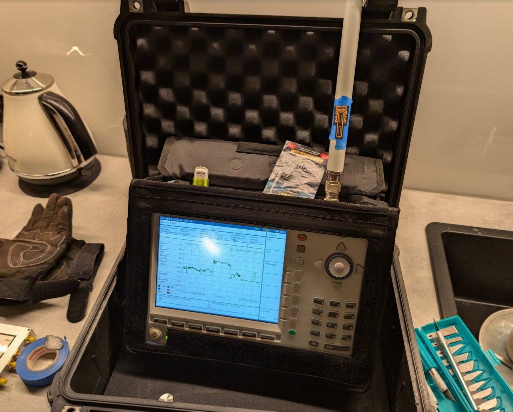
I put up a 1800Mhz (band 3) LTE carrier in my office in the other room as a reference and placed the test equipment into the test jig (between the sink and the kettle).
We then took baseline readings from the omni shown in the pictures, to get a reading on the power levels before adding the sticker.
We are reading exactly -80dBm without the sticker in place, so we expertly put some masking tape on the omni (so we could peel it off) and applied the sticker antenna to the tape on the omni antenna.
At -80dBm before, by adding the 21dB of gain, we should be put just under -60dBm, these Viavi units are solid, but I was fearful of potentially overloading the receive end from the gain, after a long discussion we agreed at these levels it was unlikely to blow the unit, so no in-line attenuation was used.
Okay, </sarcasm> I was genuinely a little surprised by what we found; there was some gain, as shown in the screenshot below.
Marker 1 was our reference without the sticker, while reference 2 was our marker with the sticker, that’s a 1.12dB gain with the sticker in place. In linear terms that’s a ~30% increase in signal strength.
Screenshot
So does this magic sticker work? Well, kinda, in as much that holding onto the Omni changes the characteristics, as would wrapping a few turns of wire around it, putting it in the kettle or wrapping it in aluminum foil. Anything you do to an antenna to change it is going to cause minor changes in characteristic behavior, and generally if you’re getting better at one frequency, you get worse at another, so the small gain on band 3 may also lead to a small loss on band 1, or something similar.
So what to make of all this? Maybe this difference is an artifact from moving the unit to make a cup of tea, the tape we applied or just a jump in the LTE carrier, or maybe the performance of this sticker is amazing after all…
Recently we were on a project and our RAN guy was seeing UEs hand between one layer and another over and over. The hysteresis and handover parameters seemed correct, but we needed a way to see what was going on, what the eNB was actually advertising and what the UE was sending back.
In a past life I had access to expensive complicated dedicated tooling that could view this information transmitted by the eNB, but now, all I need is a cellphone or a modem with a Qualcomm chip.
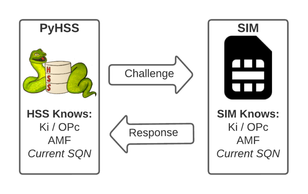
I’ve written about Milenage and SIM based security in the past on this blog, and the component that prevents replay attacks in cellular network authentication is the Sequence Number (Aka SQN) stored on the SIM.
Think of the SQN as an incrementing odometer of authentication vectors. Odometers can go forward, but never backwards. So if a challenge comes in with an SQN behind the odometer (a lower number), it’s no good.
Why the SQN is important for Milenage Security
Every time the SIM authenticates it ticks up the SQN value, and when authenticating it checks the challenge from the network doesn’t have an SQN that’s behind (lower than) the SQN on the SIM.
Let’s take a practical example of this:
The HSS in the network has SQN for the SIM as 8232, and generates an authentication challenge vector for the SIM which includes the SQN of 8232. The SIM receives this challenge, and makes sure that the SQN in the SIM, is equal to or less than 8232. If the authentication passes, the new SQN stored in the SIM is equal to 8232 + 1, as that’s the next valid SQN we’d be expecting, and the HSS incriments the counters it has in the same way.
By constantly increasing the SQN and not allowing it to go backwards, means that even if we pre-generated a valid authentication vector for the SIM, it’d only be valid for as long as the SQN hasn’t been authenticated on the SIM by another authentication request.
Imagine for example that I get sneaky access to an operator’s HSS/AuC, I could get it to generate a stack of authentication challenges that I could use for my nefarious moustache-twirling purposes whenever I wanted.
This attack would work, but this all comes crumbling down if the SIM was to attach to the real network after I’ve generated my stack of authentication challenges.
If the SQN on the SIM passes where it was when the vectors were generated, those vectors would become unusable.
It’s worth pointing out, that it’s not just evil purposes that lead your SQN to get out of Sync; this happens when you’ve got subscriber data split across multiple HSSes for example, and there’s a mechanism to securely catch the HSS’s SQN counter up with the SQN counter in the SIM, without exposing any secrets, but it just ticks the HSS’s SQN up – It never rolls back the SQN in the SIM.
The Flaw – Draining the Pool
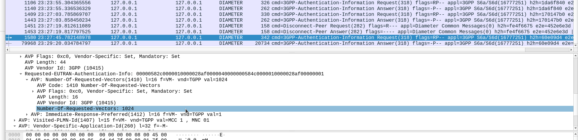
The Authentication Information Request is used by a cellular network to authenticate a subscriber, and the Authentication Information Answer is sent back by the HSS containing the challenges (vectors).
When we send this request, we can specify how many authentication challenges (vectors) we want the HSS to generate for us, so how many vectors can you generate?
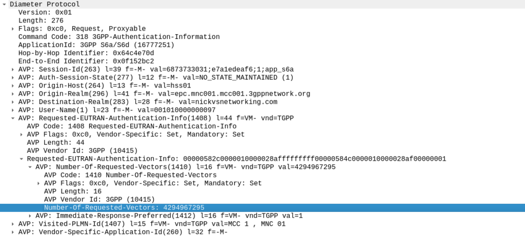
TS 129 272 says the Number-of-Requested-Vectors AVP is an Unsigned32, which gives us a possible pool of 4,294,967,295 combinations. This means it would be legal / valid to send an Authentication Information Request asking for 4.2 billion vectors.
It’s worth noting that that won’t give us the whole pool.
Sequence numbers (SQN) shall have a length of 48 bits.
TS 133 102
While the SQN in the SIM is 48 bits, that gives us a maximum number of values before we “tick over” the odometer of 281,474,976,710,656.
If we were to send 65,536 Authentication-Information-Requests asking for 4,294,967,295 a piece, we’d have got enough vectors to serve the sub for life.
Except the standard allows for an unlimited number of vectors to be requested, this would allow us to “drain the pool” from an HSS to allow every combination of SQN to be captured, to provide a high degree of certainty that the SQN provided to a SIM is far enough ahead of the current SQN that the SIM does not reject the challenges.
Can we do this?
Our lab has access to HSSes from several major vendors of HSS.
Out of the gate, the Oracle HSS does not allow more than 32 vectors to be requested at the same time, so props to them, but the same is not true of the others, all from major HSS vendors (I won’t name them publicly here).
For the other 3 HSSes we tried from big vendors, all eventually timed out when asking for 4.2 billion vectors (don’t know why that would be *shrug*) from these HSSes, it didn’t get rejected.
This is a lab so monitoring isn’t great but I did see a CPU spike on at least one of the HSSes which suggests maybe it was actually trying to generate this.
Of course, we’ve got PyHSS, the greatest open source HSS out there, and how did this handle the request?
Well, being standards compliant, it did what it was asked – I tested with 1024 vectors I’ll admit, on my little laptop it did take a while. But lo, it worked, spewing forth 1024 vectors to use.
So with that working, I tried with 4,294,967,295…
And I waited. And waited.
And after pegging my CPU for a good while, I had to get back to real life work, and killed the request on the HSS.
In part there’s the fact that PyHSS writes back to a database for each time the SQN is incremented, which is costly in terms of resources, but also that generating Milenage vectors in LTE is doing some pretty heavy cryptographic lifting.
The Risk
Dumping a complete set of vectors with every possible SQN would allow an attacker to spoof base stations, and the subscriber would attach without issue.
Historically this has been very difficult to do for LTE, due to the mutual network authentication, however this would be bypassed in this scenario.
The UE would try for a resync if the SQN is too far forward, which mitigates this somewhat.
Cryptographically, I don’t know enough about the Milenage auth to know if a complete set of possible vectors would widen the attack surface to try and learn something about the keys.
Mitigations / Protections
So how can operators protect ourselves against this kind of attack?
Different commercial HSS vendors handle this differently, Oracle limits this to 32 vectors, and that’s what I’ve updated PyHSS to do, but another big HSS vendor (who I won’t publicly shame) accepts the full 4294967295 vectors, and it crashes that thread, or at least times it out after a period.
If you’ve got a decent Diameter Routing Agent in place you can set your DRA to check to see if someone is using this exploit against your network, and to rewrite the number of requested vectors to a lower number, alert you, or drop the request entirely.
Having common OP keys is dumb, and I advocate to all our operator customers to use OP keys that are unique to each SIM, and use the OPc key derived anyway. This means if one SIM spilled it’s keys, the blast doesn’t extend beyond that card.
In the long term, it’d be good to see 3GPP limit the practical size of the Number-of-Requested-Vectors AVP.
2G/3G Impact
Full disclosure – I don’t really work with 2G/3G stacks much these days, and have not tested this.
MAP is generally pretty bandwidth constrained, and to transfer 280 billion vectors might raise some eyebrows, burn out some STPs and take a long time…
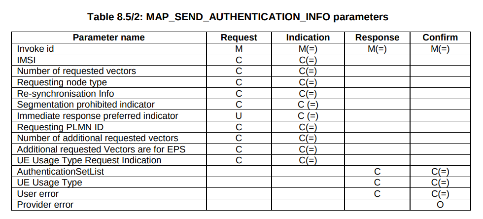
But our “Send Authentication Info” message functions much the same as the Authentication Information Request in Diameter, 3GPP TS 29.002 shows we can set the number of vectors we want:
5GC Vulnerability
This only impacts LTE and 5G NSA subscribers.
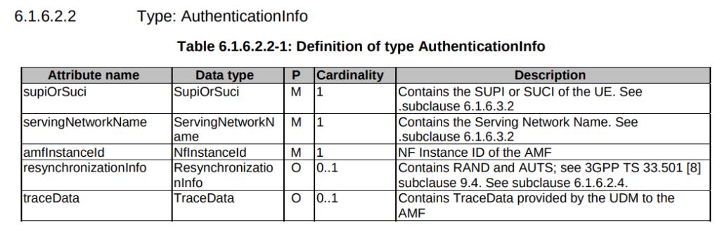
TS 29.509 outlines the schema for the Nausf reference point, used for requesting vectors, and there is no option to request multiple vectors.
Summary
If you’ve got baddies with access to your HSS / HLR, you’ve got some problems.
But, with enough time, your pool could get drained for one subscriber at a time.
This isn’t going to get the master OP Key or plaintext Ki values, but this could potentially weaken the Milenage security of your system.