So let’s roll up our sleeves and get a Lab scenario happening,
To keep things (relatively) simple, I’ve put the eNodeB on the same subnet as the MME and Serving/Packet-Gateway.
So the traffic will flow from the eNodeB to the S/P-GW, via a simple Network Switch (I’m using a Mikrotik).
While life is complicated, I’ll try and keep this lab easy.
Experiment 1: MTU of 1500 everywhere
Network Element
MTU
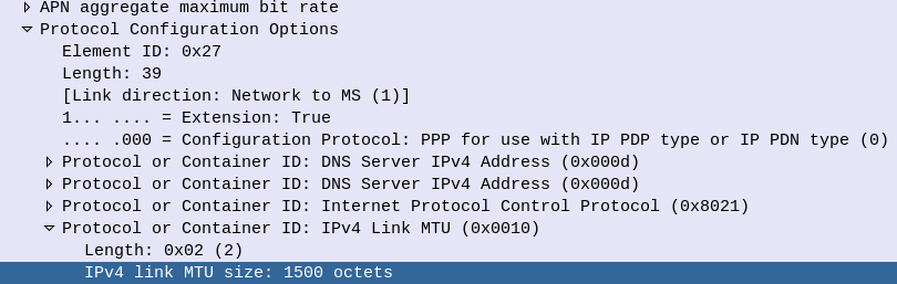
Advertised MTU in PCO
1500
eNodeB
1500
Switch
1500
Core Network (S/P-GW)
1500
So everything attaches and traffic flows fine. There is no problem right?
Well, not a problem that is immediately visible.
While the PCO advertises the MTU value at 1500 if we look at the maximum payload we can actually get through the network, we find that’s not the case.
This means if our end user on a mobile device tried to send a 1500 byte payload, it’d never get through.
While DNS would work, most TCP traffic would flow fine, certain UDP applications would start to fail if they were sending payloads nearing 1500 bytes.
So why is this?
Well GTP adds overhead.
8 bytes for the GTP header
8 bytes for the transport UDP header
20 bytes for the transport IPv4 header
14 bytes if our transport is using Ethernet
For a total of 50 bytes of overhead, assuming we’re not using MPLS, QinQ or anything else funky on our transport network and just using Ethernet.
So we have two options here – We can either lower the MTU advertised in our Protocol Configuration Options, or we can increase the MTU across our transport network. Let’s look at each.
Experiment 2: Lower Advertised MTU in PCO to 1300
Well this works, and looks the same as our previous example, except now we know we can’t handle payloads larger than 1300 without fragmentation.
Experiment 3: Increase MTU across transmission Network
While we need to account for the 50 bytes of overhead added by GTP, I’ve gone the safer option and upped the MTU across the transport to 1600 bytes.
With this, we can transport a full 1500 byte MTU on the UE layer, and we’ve got the extra space by enabling jumbo frames.
Obviously this requires a change on all of the transmission layer – And if you have any hops without support for this, you’ll loose packets.
Conclusions?
Well, fragmentation is bad, and we want to avoid it.
For this we up the MTU across the transmission network to support jumbo frames (greater than 1500 bytes) so we can handle the 1500 byte payloads that users want.
In our last post we covered the basics of NB-IoT Non-IP Data Deliver (NIDD), and if that acronym soup wasn’t enough for you, we’re going to take a deep dive into the flows for attaching, sending, receiving and closing a NIDD session.
The attach for NIDD is very similar to the standard attach for wideband LTE, except the MME establishes a connection on the T6a Diameter interface toward the SCEF, to indicate the sub is online and available.
The NIDD Attach
The SCEF is now able to send/receive NIDD traffic from the subscriber on the T6a interface, but in reality developers don’t / won’t interact with Diameter, so the SCEF exposes the T8 API that developers can interact with to access an abstraction layer to interact with the SCEF, and then through onto the UE.
If you’re wondering what the status of Open Source SCEF implementations are, then you may have already guessed we’re working on one! PyHSS should have support for NB-IoT SCEF features in the future.
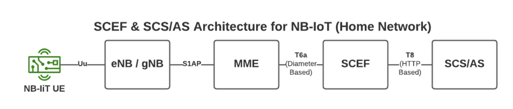
NB-IoT provides support for Non-IP Data Delivery (NIDD) over 3GPP Networks, but to handle this, some new network elements are introduced, in a home network scenario that’s the SCEF and the SCF/AS.
On the 3GPP side the SCEF it communicates to the MME via the T6a Interface, which is based upon Diameter.
On the side towards our IoT Service Consumers (in the standards referred to as “SCS/AS” or “Service Capabilities Server Application Servers” (catchy names as always), via the RESTful HTTP based T8 interface.
The start of the S1 Attach procedure is very similar to a regular S1 attach.
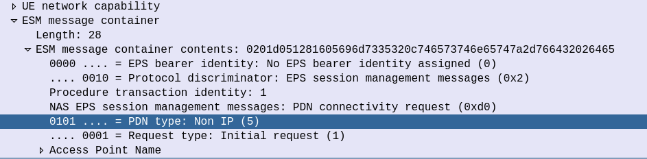
The initial S1 PDU Connectivity Request indicates in the ESM Message Container that the PDN Type is Non IP.
S1 PDU Connectivity Request from attach procedure
Other than that, the initial attach procedure looks very similar to the regular S1 attach procedure.
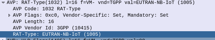
On the S6a interface the Update Location Request from the MME to the HSS indicates that this is an EUTRAN-NB-IoT Radio Access Type.
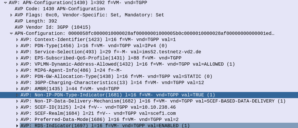
And the Update Location Answer APN Configuration contains some additional AVPs on the APN to indicate that the APN supports Non-IP-PDN-Type and that the SCEF is used for Data Delivery.
The SCEF-ID (Diameter Host) and SCEF-Realm (Diameter realm) to serve this user is also specified in the APN Configuration in the Update Location Answer.
This is how our MME determines where to send the T6a traffic.
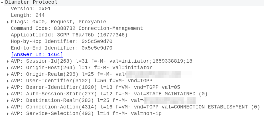
With this, the MME sends a Connection Management Request (CMR) towards the SCEF specified in the SCEF-ID returned by the HSS.
The Connection Management Request / Response
The MME now sends a Diameter T6a Connection Management Request to the SCEF in the Update Location Answer,
In it we have a Session-Id, which continues for the life of our NIDD session, the service-selection which contains our APN (In our case “non-ip”) and the User-Identifier AVP which contains the MSISDN and/or IMSI of the subscriber.
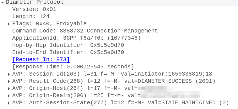
To accept this, the SCEF sends back a Connection-Management-Answer to confirm we’re all good to go:
At this point our SCEF now knows about the subscriber who’s just attached to our network, and correlates it with the APN and the session-ID.
On the S1 side the connection is confirmed and we’re ready to roll.
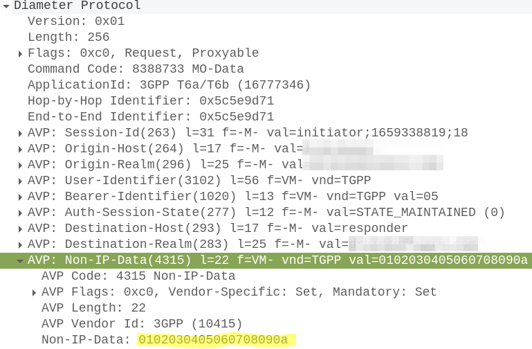
Mobile Originated Data Request / Response
When the UE wants to send NIDD it’s carried in NAS messaging, so we see an Uplink NAS transport from the UE and inside the NAS payload itself is our HEX data.
Our MME grabs this out and sends it in the form of of a Mobile-Originated-Data-Request (MODR) to the SCEF, along with the same Session-ID that was setup earlier:
At this stage our Non-IP Data is exposed over the T8 RESTful API, which we won’t cover in this post.
PyHSS is our open source Home Subscriber Server, it’s written in Python, has a variety of different backends, and is highly perforate (We benchmark to 10K transactions per second) and infinitely scaleable.
In this post I’ll cover the basics of setting up PyHSS in your enviroment and getting some Diameter peers connected.
For starters, we’ll need a database (We’ll use MySQL for this demo) and an account on that database for a MySQL user.
So let’s get that rolling (I’m using Ubuntu 24.04):
sudo apt update
sudo apt install mysql-server
Next we’ll create the MySQL user for PyHSS to use:
CREATE USER 'pyhss_user'@'%' IDENTIFIED BY 'pyhss_password';
GRANT ALL PRIVILEGES ON *.* TO 'pyhss_user'@'%' WITH GRANT OPTION;
FLUSH PRIVILEGES;
We’ll also need Redis as well (PyHSS uses Redis for inter-service communications and for caching), so go ahead an install that for your distro:
sudo apt install redis-server
So that’s our prerequisites sorted, let’s clone the PyHSS repo:
And install the requirements with pip from the PyHSS repo:
pip3 install -r requirements.txt
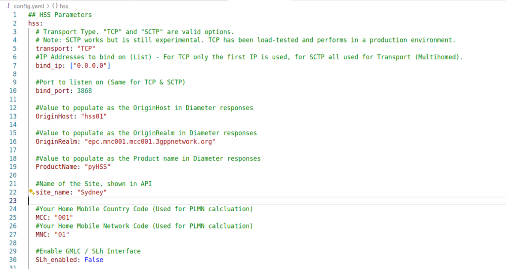
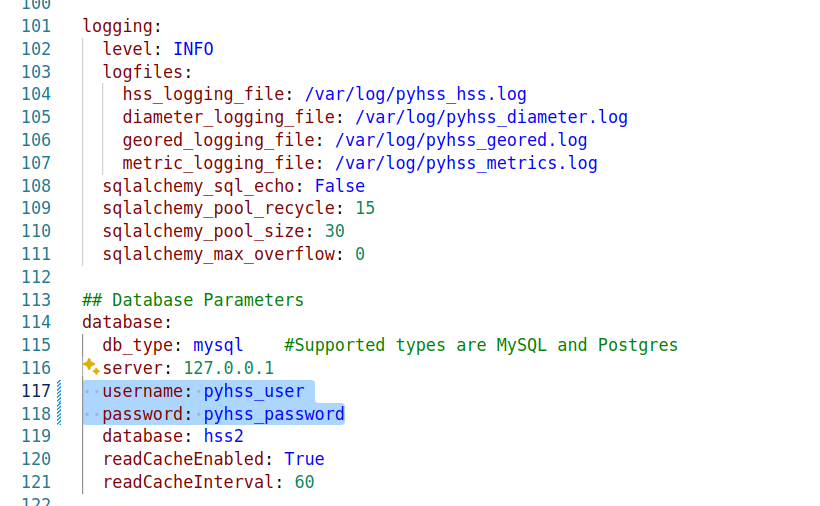
Next we’ll need to configure PyHSS, for that we update the config file (config.yaml) with the settings we want to use.
We’ll start by setting the bind_ip to a list of IPs you want to listen on, and your transport – We can use either TCP or SCTP.
For Diameter, we will set OriginHost and OriginRealm to match the Diameter hostname you want to use for this peer, and the Realm of your Diameter network.
Lastly we’ll need to set the database parameters, updating the database: section to populate your credentials, setting your username and password and the database to match your SQL installation we setup at the start.
With that done, we can start PyHSS, which we do using systemctl.
Because there’s multiple microservices that make up PyHSS, there’s multiple systemctl files use to run PyHSS as a service, they’re all in the /systemd folder.
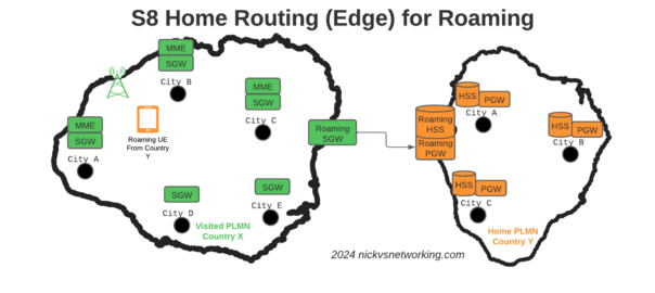
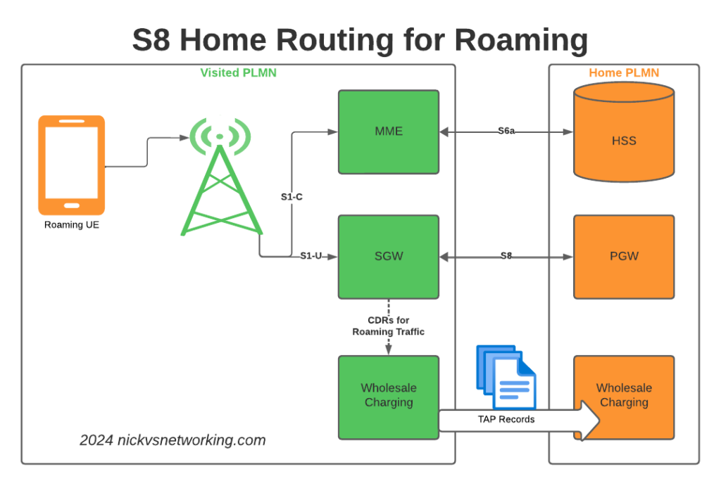
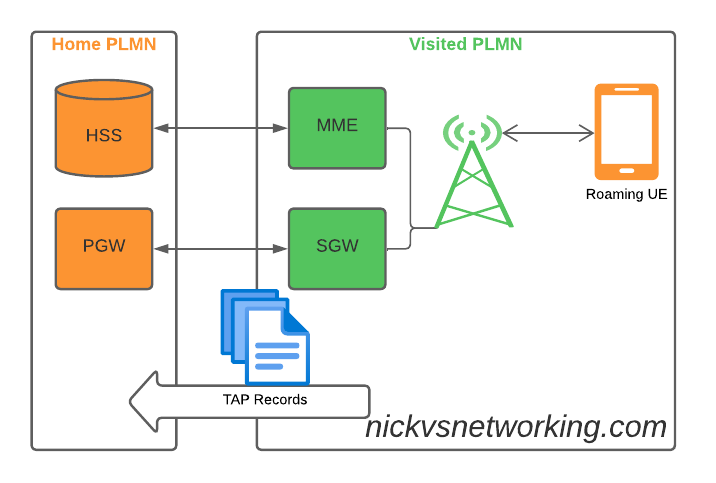
S8 Home Routing is a really simple concept, the traffic goes from the SGW in the visited PLMN to the PGW in the home PLMN, so the PCRF, OCS/OFCS, IMS, IP Addresses, etc, etc, are all in the home network, and this avoids huge amounts of complexity.
But in order for this to work, the visited network MME needs to find the PGW of the home network, and with over 700 roaming networks in commercial use, each one with potentially hundreds of unique APNs each routing to a different PGW, this is a tricky proposition.
If you’ve configured your PGW peers statically on your MME, that’s fine, but it doesn’t scale very well – And if you add an MVNO who wants their own PGW for serving their APN, well you’ll be adding some complexity there to, so what to do?
Well, the answer is DNS.
By taking the APN to be served, the home PLMN and the interface type desired, with some funky DNS queries, our MME can determine which PGW should be selected for a request.
Let’s take a look, for a UE from MNC XXX MCC YYY roaming into our network, trying to access the “IMS” APN.
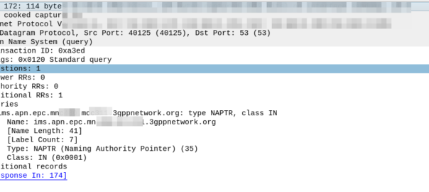
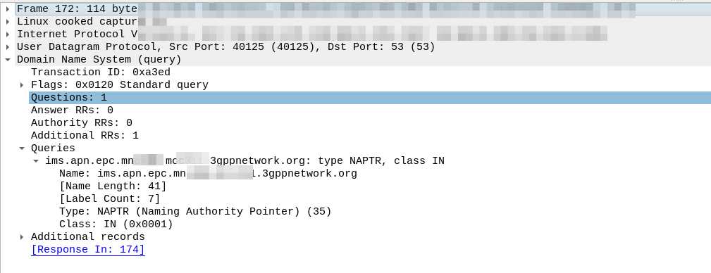
Our MME knows the network code of the roaming subscriber from the IMSI is MNC XXX, MCC YYY, and that the UE is requesting the IMS APN.
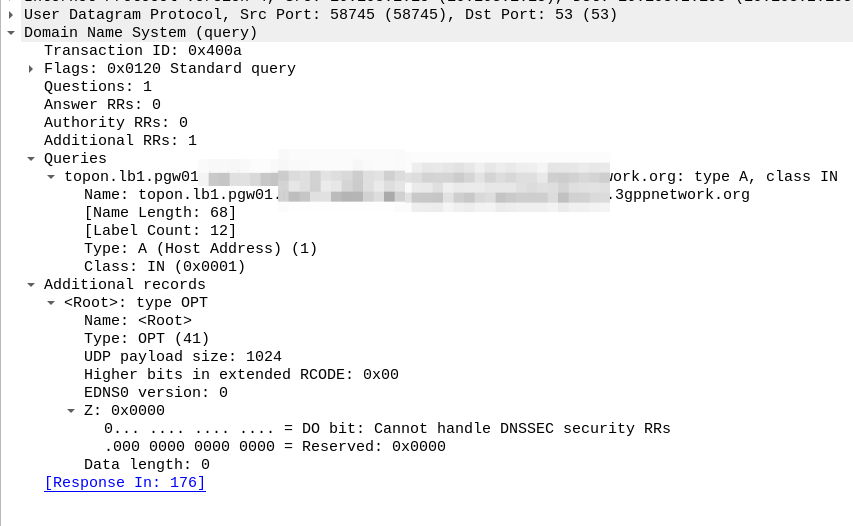
So our MME crafts a DNS request for the NAPTR query for ims.apn.epc.mncXXX.mccYYY.3gppnetwork.org:
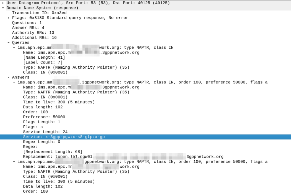
Because the domain is epc.mncXXX.mccYYY.3gppnetwork.org it’s routed to the authoritative DNS server in the home network, which sends back the response:
We’ve got a few peers to pick from, so we need to filter this list of Answers to only those that are relevant to us.
First we filter by the Service tag, whihc for each listed peer shows what services that peer supports.
But since we’re looking for S8, we need to find a peer who’s “Service” tag string contains:
x-3gpp-pgw:x-s8-gtp
We’re looking for two bits of info here, the presence of x-3gpp-pgw in the Service to indicate that this peer is a PGW and x-s8-gtp to indicate that this peer supports the S8 interface.
A service string like this:
x-3gpp-pgw:x-s5-gtp
Would be excluded as it only supports S5 not S8 (Even though they are largely the same interface, S8 is used in roaming).
It’s also not uncommon to see both services indicated as supported, in which case that peer could be selected too:
x-3gpp-pgw:x-s5-gtp:x-s8-gtp
(The answers in the screenshot include :x-gp which means the PGWs advertised are also co-located with a GGSN)
So with our answers whittled down to only those that meet our needs, we next use the Order and the Preference to pick our best candidate, this is the same as regular DNS selection logic.
From our candidate, we’ve also got the Regex Replacement, which allows our original DNS request to be re-written, which allows us to point at a single peer.
In our answer, we see the original request ims.apn.epc.mncXXX.mccYYY.3gppnetwork.org is to be re-written to topon.lb1.pgw01.epc.mncXXX.mccYYY.3gppnetwork.org.
This is the FQDN of the PGW we should use.
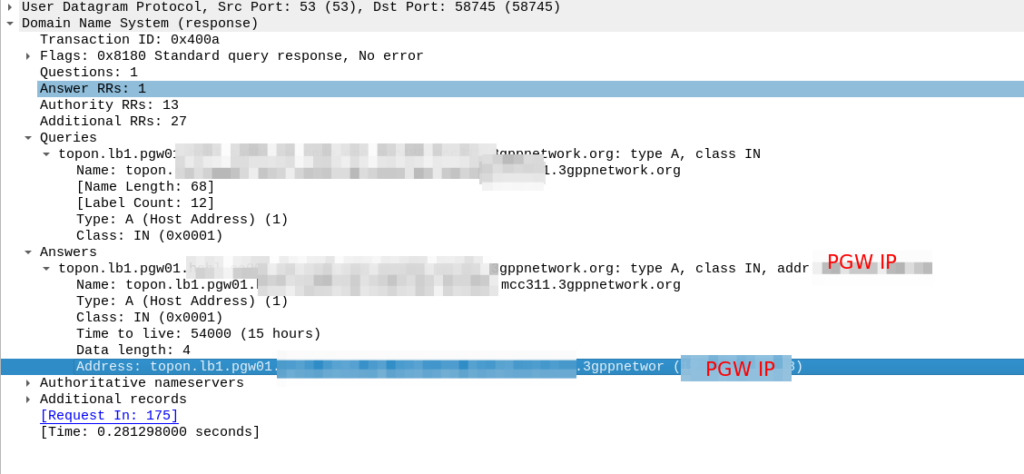
Now we know the FQND we should use, we just do an A-Record lookup (Or AAAA record lookup if it is IPv6) for that peer we are targeting, to turn that FQDN into an IP address we can use.
And then in comes the response:
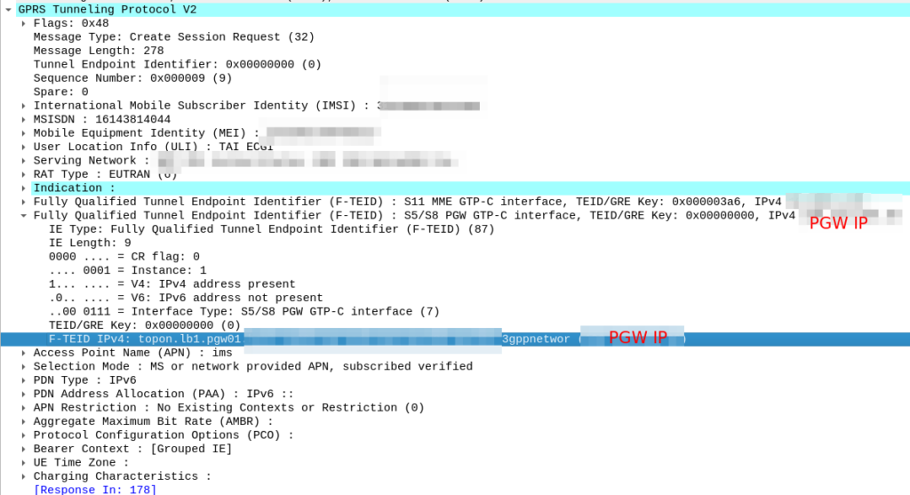
So now our MME knows the IP of the PGW, it can craft a Create Session request where the F-TEID for the S8 interface has the PGW IP set on it that we selected.
For more info on this TS 129.303 (Domain Name System Procedures) is the definitive doc, but the GSMA’s IR.88 “LTE and EPC Roaming Guidelines” provides a handy reference.
The S8 Home Routing approach for LTE Roaming works really well, as more and more operators are switching off their legacy circuit switched 2G/3G networks and shifting to LTE & VoLTE for roaming, we’re seeing more an more S8-HR deployments.
When LTE was being standardised in 2008, Local Breakout (LBO) and S8 Home Routing were both considered options for how roaming may look. Fast forward to today, and S8 Home routing is the only way roaming is done for modern deployments.
In light of this, there are some “best practices” in an “all S8 Home Routed” world, we’ve developed, that I thought I’d share.
The Basics
When roaming, the SGW in the Visited Network, sends user traffic back to the PGW in the Home Network.
This means Online/Offline charging, IMS, PCRF, etc, is all done in the Home PLMN. As long as data packets can get from the SGW in the Visited PLMN to the PGW in the Home PLMN, and authentication flows from the Visited MME to the HSS in the Home PLMN, you’re golden.
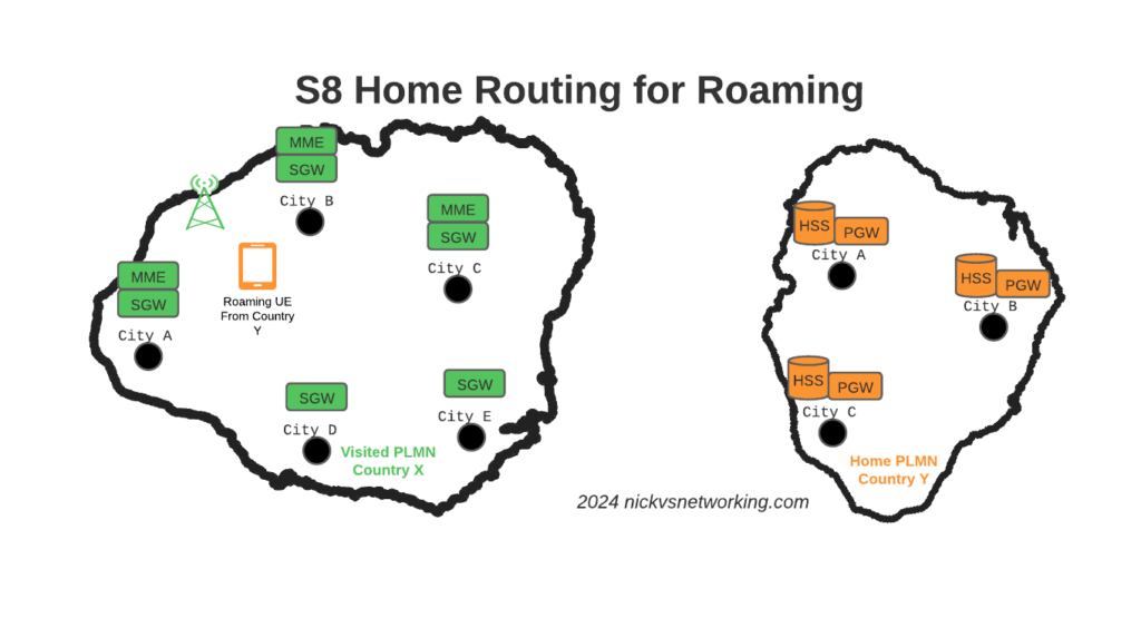
The Constraints
Of course real networks don’t look as simple as this, in reality a roaming scenario for a visited network has a lot more nodes, which need to be
Building Distributed Packet Core & IMS
Virtualization (VNF / CNF) has led operators away from “big iron” hardware for Packet Core & IMS nodes, towards software based solutions, which in turn offer a lot more flexibility.
Best practice for design of User Plane is to keep the the latency down, by bringing the user plane closer to the user (the idea of “Edge” UPFs in 5GC is a great example of this), and the move away from “big iron” in central locations for SGW and PGW nodes has been the trend for the past decade.
So to achieve these goals in the networks we build, we geographically distribute the core network.
This means we’ve got quite a few S-GW, P-GW, MME & HSS instances across the network. There’s some real advantages to this approach:
From a redundancy perspective this allows us to “spread the load” and build far more resilient networks. A network with 20 smaller HSS instances spread around the country, is far more resilient than 2 massive ones, regardless of how many power feeds or redundant disks it may have.
This allows us to be more resource efficient. MNOs have always provisioned excess capacity to cater for the loss of a node. If we have 2 MMEs serving a country, then each node has to have at least 50% capacity free, so if one MME were to fail, the other MME could handle the additional load it from it’s dead friend. This is costly for resources. Having 20 MMEs means each MME has to have 5% capacity free, to handle the loss of one MME in the pool.
It also forces our infrastructure teams to manage infrastructure “as cattle” rather than pets. These boxes don’t get names or lovingly crafted, they’re automatically spun up and destroyed without thinking about it.
For security, we only use internal IP addresses for the nodes in our packet core, this provides another layer of protection for the “crown jewels” of our network, so no one messing with BGP filtering can accidentally open the flood gates to our core, as one US operator learned leaving a GGSN open to the world leading to the private information for 100 million customers being leaked.
What this all adds to, is of course, the end user experience. For the end subscriber / customer, they get a better experience thanks to the reduced latency the connection provides, better uptime and faster call setup / SMS delivery, and less cost to deliver services.
I love this approach and could prothletise about it all day, but in a roaming context this presents some challenges.
The distributed networks we build are in a constant state of flux, new capacity is being provisioned in some areas, nodes things decommissioned in others, and our our core nodes are only reachable on internal IPs, so wouldn’t be reachable by roaming networks.
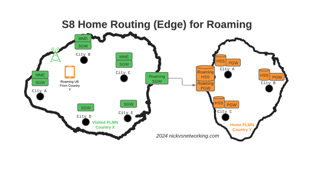
Our Distributed-Core Roaming Solution
To resolve this we’ve taken a novel approach, we’ve deployed a pair of S-GWs we call the “Roaming SGWs”, and a pair of P-GWs we call the “Roaming PGWs”, these do have public IPs, and are dedicated for use only by roaming traffic.
We really like this approach for a few reasons:
It allows us to be really flexible do what we want inside the network, without impacting roaming customers or operators who use our network for roaming. All the benefits I described from the distributed architectures can still be realised.
From a security standpoint, only these SGW/PGW pairs have public IPs, all the others are on internal IPs. This good for security – Our core network is the ‘crown jewels’ of the network and we only expose an edge to other providers. Even though IPX networks are supposed to be secure, one of the largest IPX providers had their systems breached for 5 years before it was detected, so being almost as distrustful of IPX traffic as Internet traffic is a good thing. This allows us to put these PGWs / SGWs at the “edge” of our network, and keep all our MMEs, as well as our on-net PGW and SGWs, on internal IPs, safe and secure inside our network.
For charging on the SGWs, we only need to worry about collecting CDRs from one set of SGWs (to go into the TAP files we use to bill the other operators), rather than running around hoovering up SGW CDRs from large numbers of Serving Gateways, which may get blown away and replaced without warning.
Of course, there is a latency angle to this, for international roaming, the traffic has to cross the sea / international borders to get to us. By putting it at the edge we’re seeing increased MOS on our calls, as the traffic is as close to the edge of the network as can be.
Caveat: Increased S11 Latency on Core Network sites over Satellite
This is probably not relevant to most operators, but some of our core network sites are fed only by satellite, and the move to this architecture shifted something: Rather than having latency on the S8 interface from the SGW to the PGW due to the satellite hop, we’ve got latency between the MME and the SGW due to the satellite hop.
It just shifts where in the chain the latency lies, but it did lead to us having to boost some timers in the MME and out of sequence deliver detection, on what had always been an internal interface previously.
Evolution to 5G Standalone Roaming
This approach aligns to the Home Routed options for 5G-SA roaming; UPF chaining means that the roaming traffic can still be routed, as seems to be the way the industry is going.
SA roaming is in its infancy, without widely deployed SA networks, we’re not going to see common roaming using SA for a good long while, but I’ll be curious to see if this approach becomes the de facto standard going forward.
Where to from here?
We’re pretty happy with this approach in the networks we’ve been building.
So far it’s made IREG testing easier as we’ve got two fixed points the IPX needs to hit (The DRAs and the SGWs) rather than a wide range of networks.
Operators with a vast number of APNs they need to drop into different VRFs may have to do some traffic engineering here – Our operations are generally pretty flat, but I can see where this may present some challenges for established operators shifting their traffic.
I’d be keen to hear if other operators are taking this approach and if they’ve run into any issues, or any issues others can see in this, feel free to drop a comment below.
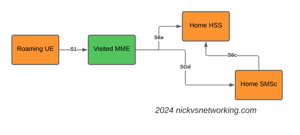
SGs-AP which is used for CSFB & SMS doesn’t span network borders (you can’t roam with SGs-AP), and with SMSoIP out of the question, that gave us the option of MAP or Diameter, so we picked Diameter.
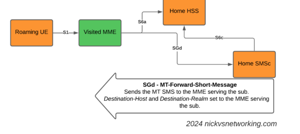
This introduces the S6c and SGd Diameter interfaces, in the diagrams below Orange is the Home Network (HPMN) and the Green is the Visited Network (VPMN).
The S6c interface is used between the SMSc and the HSS, in order to retrieve the routing information. This like the SRI-for-SM in MAP.
The SGd interface is used between the MME serving the UE and the SMSc, and is used for actual delivery of the MO/MT messages.
I haven’t shown the Diameter Routing Agents in these diagrams, but in reality there would be a DRA on the VPLMN and a DRA on the HPMN, and probably a DRA in the IPX between them too.
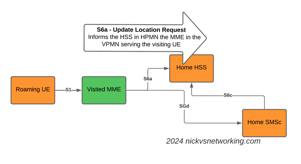
The Attach
The attach looks like a regular roaming attach, the MME in the Visited PMN sends an Update Location Request to the HSS, so the HSS knows the MME that is serving the subscriber.
S6a Update Location Request to indicate the MME serving the Subscriber
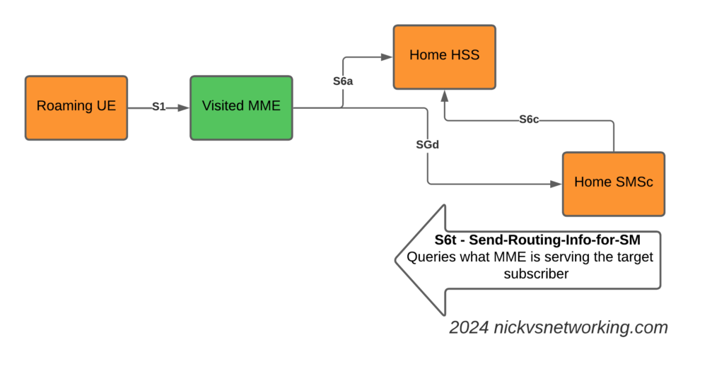
The Mobile Terminated SMS Flow
Now we introduce the S6c interface and the SGd interfaces.
When the Home SMSc has a message to send to the subscriber (Mobile Terminated SMS) it runs a the Send-Routing-Info-for-SM-Request (SRR) dialog to the HSS.
The Send-Routing-Info-for-SM-Answer (SRA) back from the HSS contains the info on the MME Diameter Host name and Diameter Realm serving the subscriber.
S6t – Send-Routing-Info-for-SM request to get the MME serving the subscriber
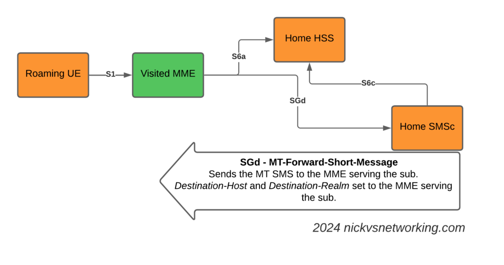
With this info, we can now craft a Diameter Request that will get sent to the MME serving the subscriber, containing the SMS PDU to send to the UE.
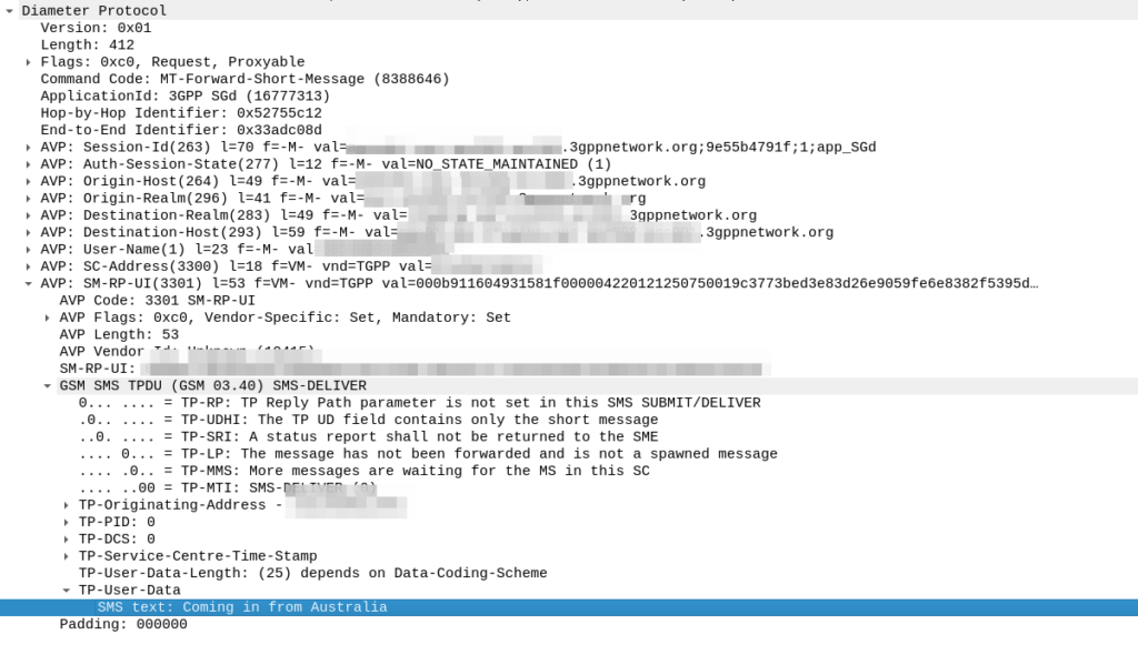
SGd MT-Forward-Short-Message to deliver Mobile Terminated SMS to the serving MME
We make sure it’s sent to the correct MME by setting the Destination-Host and Destination-Realm in the Diameter request.
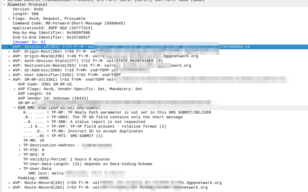
Here’s how the request looks from the SMSc towards our DRA:
As you can see the Destination Realm and Destination-Host is set, as is the User-Name set to the IMSI of the UE we want to send the message to.
And down the bottom you can see the SMS-TPDU, the same as it’s been all the way back since GSM days.
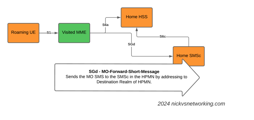
The Mobile Originated SMS Flow
The Mobile Originated flow is even simpler, because we don’t need to look up where to route it to.
The MME receives the MO SMS from the UE, and shoves it into a Diameter message with Application ID set to SGd and Destination-Realm set to the HPMN Realm.
When the message reaches the DRA in the HPMN it forwards the request to an SMSc and then the Home SMSc has the message ready to roll.
Advanced Mobile Location (AML) is being rolled out by a large number of mobile network operators to provide accurate caller location to emergency services, so how does it work, what’s going on and what do you need to know?
Recently we’ve been doing a lot of work on emergency calling in IMS, and meeting requirements for NG-112 / e911, etc.
This led me to seeing my first Advanced Mobile Location (AML) SMS in the wild.
For those unfamiliar, AML is a fancy text message that contains the callers location, accuracy, etc, that is passed to emergency services when you make a call to emergency services in some countries.
It’s sent automatically by your handset (if enabled) when making a call to an emergency number, and it provides the dispatch operator with your location information, including extra metadata like the accuracy of the location information, height / floor if known, and level of confidence.
Google has their own version of AML called ELS, which they claim is supported on more than 99% of Android phones (I’m unclear on what this means for Harmony OS or other non-Google backed forks of Android), and Apple support for AML starts from iOS 11 onwards, meaning it’s supported on iPhones from the iPhone 5S onards,.
Call Flow
When a call is made to the PSAP based on the Emergency Calling Codes set on the SIM card or set in the OS, the handset starts collecting location information. The phone can pull this from a variety of sources, such as WiFi SSIDs visible, but the best is going to be GPS or one of it’s siblings (GLONASS / Galileo).
Once the handset has a good “lock” of a location (or if 20 seconds has passed since the call started) it bundles up all of this information the phone has, into an SMS and sends it to the PSAP as a regular old SMS.
The routing from the operator’s SMSc to the PSAP, and the routing from the PSAP to the dispatcher screen of the operator taking the call, is all up to implementation. For the most part the SMS destination is the emergency number (911 / 112) but again, this is dependent on the country.
Inside the SMS
To the user, the AML SMS is not seen, in fact, it’s actually forbidden by the standard to show in the “sent” items list in the SMS client.
On the wire, the SMS looks like any regular SMS, it can use GSM7 bit encoding as it doesn’t require any special characters.
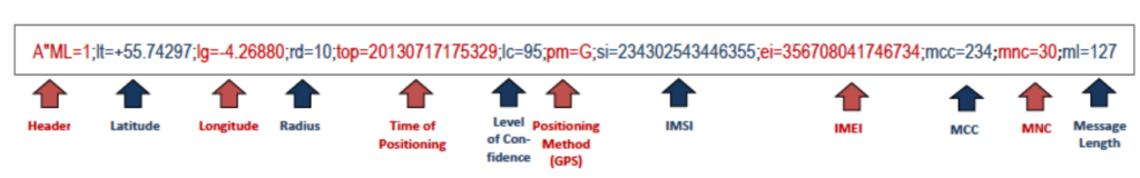
Each attribute is a key / value pair, with semicolons (;) delineating the individual attributes, and = separating the key and the value.
If you’ve got a few years of staring at Wireshark traces in Hex under your belt, then this will probably be pretty easy to get the gist of what’s going on, we’ve got the header (A”ML=1″) which denotes this is AML and the version is 1.
After that we have the latitude (lt=), longitude (lg=), radius (rd=), time of positioning (top=), level of confidence (lc=), positioning method (pm=) with G for GNSS, W for Wifi signal, C for Cell or N for a position was not available, and so on.
AML outside the ordinary
Roaming Scenarios
If an emergency occurs inside my house, there’s a good chance I know the address, and even if I don’t know my own address, it’s probably linked to the account holder information from my telco anyway.
AML and location reporting for emergency calls is primarily relied upon in scenarios where the caller doesn’t know where they’re calling from, and a good example of this would be a call made while roaming.
If I were in a different country, there’s a much higher likelihood that I wouldn’t know my exact address, however AML does not currently work across borders.
The standard suggests disabling SMS when roaming, which is not that surprising considering the current state of SMS transport.
Without a SIM?
Without a SIM in the phone, calls can still be made to emergency services, however SMS cannot be sent.
That’s because the emergency calling standards for unauthenticated emergency calls, only cater for
This is a limitation however this could be addressed by 3GPP in future releases if there is sufficient need.
HTTPS Delivery
The standard was revised to allow HTTPS as the delivery method for AML, for example, the below POST contains the same data encoded for use in a HTTP transaction:
Implementation of this approach is however more complex, and leads to little benefit.
The operator must zero-rate the DNS, to allow the FQDN for this to be resolved (it resolves to a different domain in each country), and allow traffic to this endpoint even if the customer has data disabled (see what happens when your handset has PS Data Off ), or has run out of data.
Due to the EU’s stance on Net Neutrality, “Zero Rating” is a controversial topic that means most operators have limited implementation of this, so most fall back to SMS.
Other methods for sharing location of emergency calls?
In some upcoming posts we’ll look at the GMLC used for E911 Phase 2, and how the network can request the location from the handset.
In the cellular world, subscribers are charged for data from the IP, transport and applications layers; this means you pay for the IP header, you pay for the TCP/UDP header, and you pay for the contents (the cat videos it contains).
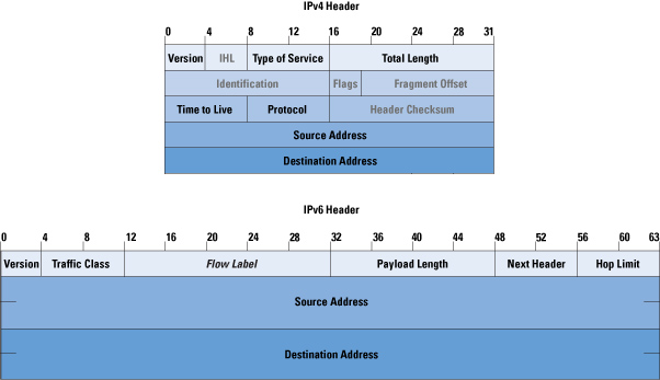
This also means if an operator moves mobile subscribers from IPv4 to IPv6, there’s an extra 20 bytes the customer is charged for for every packet sent / received, which the customer is charged for – This is because the IPv6 header is longer than the IPv4 header.
In most cases, mobile subs don’t get a choice as to if their connection is IPv4 or IPv6, but on a like for like basis, we can say that if a customer moves is on IPv6 every packet sent/received will have an extra 20 bytes of data consumed compared to IPv4.
This means subscribers use more data on IPv6, and this means they get charged for more data on IPv6.
For IoT applications, light users and PAYG users, this extra 20 bytes per packet could add up to something significant – But how much?
We can quantify this, but we’d need to know the number of packets sent on average, and the quantity of the data transferred, because the number of packets is the multiplier here.
So for starters I’ve left a phone on the desk, it’s registered to the network but just sitting in Idle mode – This is an engineering phone from an OEM, it’s just used for testing so doesn’t have anything loaded onto it in terms of apps, it’s not signed into any applications, or checking in the background, so I thought I’d try something more realistic.
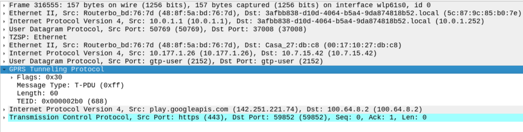
So to get a clearer picture, I chucked a SIM in my regular everyday phone I use personally, registered it to the cellular lab I have here. For the next hour I sniffed the GTP traffic for the phone while it was sitting on my desk, not touching the phone, and here’s what I’ve got:
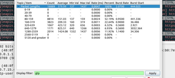
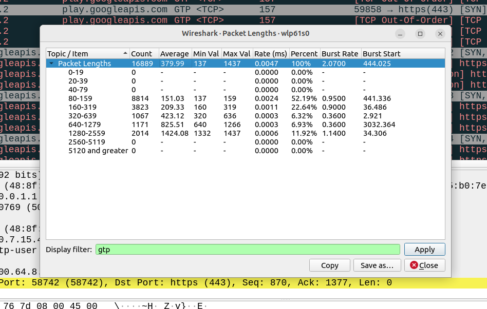
Overall the PCAP includes 6,417,732 bytes of data, but this includes the transport and GTP headers, meaning we can drop everything above it in our traffic calculations.
For this I’ve got 14 bytes of ethernet, 20 bytes IP, 8 bytes UDP and 5 bytes for TZSP (this is to copy the traffic from the eNB to my local machine), then we’ve got the transport from the eNB to the SGW, 14 bytes of ethernet again, 20 bytes of IP , 8 bytes of UDP and 8 bytes of GTP then the payload itself. Phew. All this means we can drop 97 bytes off every packet.
We have 16,889 packets, 6,417,732 bytes in total, minus 97 bytes from each gives us 1,638,233 of headers to drop (~1.6MB) giving us a total of 4.556 MB traffic to/from the phone itself.
This means my Android phone consumes 4.5 MB of cellular data in an hour while sitting on the desk, with 16,889 packets in/out.
Okay, now we’re getting somewhere!
So now we can answer the question, if each of these 16k packets was IPv6, rather than IPv4, we’d be adding another 20 bytes to each of them, 20 bytes x 16,889 packets gives 337,780 bytes (~0.3MB) to add to the total.
If this traffic was transferred via IPv6, rather than IPv4, we’d be looking at adding 20 bytes to each of the 16,889 packets, which would equate to 0.3MB extra, or about 7% overhead compared to IPv4.
But before you go on about what an outrage this IPv6 transport is, being charged for those extra bytes, that’s only one part of the picture.
There’s a reason operators are finally embracing IPv6, and it’s not to put an extra 7% of traffic on the network (I think if you asked most capacity planners, they’d say they want data savings, not growth).
IPv6 is, for lack of a better term, less rubbish than IPv4.
There’s a lot of drivers for IPv6, and some of these will reduce data consumption. IPv6 is actually your stuff talking directly to the remote stuff, this means that we don’t need to rely on NAT, so no need to do NAT keepalives, and opening new sessions, which is going to save you data. If you’re running apps that need to keep a connection to somewhere alive, these data savings could negate your IPv6 overhead costs.
Will these potential data savings when using IPv6 outweigh the costs?
That’s going to depend on your use case.
If you’ve extremely bandwidth / data constrained, for example, you have an IoT device on an NTN / satellite connection, that was having to Push data every X hours via IPv4 because you couldn’t pull data from it as it had no public IP, then moving it to IPv6 so you can pull the data on the public IP, on demand, will save you data. That’s a win with IPv6.
If you’re a mobile user, watching YouTube, getting push notifications and using your phone like a normal human, probably not, but if you’re using data like a normal user, you’ve probably got a sizable data allowance that you don’t end up fully consuming, and the extra 20 bytes per packet will be nothing in comparison to the data used to watch a 2k video on your small phone screen.
I had a question recently on LinkedIn regarding how to preference Voice over WiFi traffic so that a network engineer operating the WiFi network can ensure the best quality of experience for Voice over WiFi.
Voice over WiFi is underpinned by the ePDG – Evolved Packet Data Gateway (this is a fancy IPsec tunnel we authenticate to using the SIM to drop our traffic into the P-CSCF over an unsecured connection). To someone operating a WiFi network, the question is how do we prioritise the traffic to the ePDGs and profile it?
ePDGs can be easily discovered through a simple DNS lookup, once you know the Mobile Network Code and Mobile Country code of the operators you want to prioritise, you can find the IPs really easily.
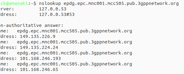
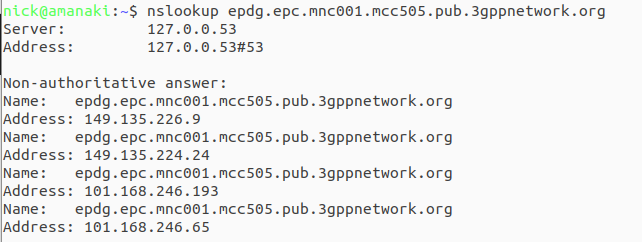
ePDG addresses take the form epdg.epc.mncXXX.mccYYY.pub.3gppnetwork.org so let’s look at finding the IPs for each of these for the operators in a country:
The first step is nailing down the mobile network code and mobile country codes of the operators you want to target, Wikipedia is a great source for this information. Here in Australia we have the Mobile Country Code 505 and the big 3 operators all support Voice over WiFi, so let’s look at how we’d find the IPs for each. Telstra has mobile network code (MNC) 01, in 3GPP DNS we always pad network codes to 3 digits, so that’ll be 001, and the mobile country code (MCC) for Australia is 505. So to find the IPs for Telstra we’d run an nslookup for epdg.epc.mnc001.mcc505.pub.3gppnetwork.org – The list of IPs that are returned, are the IPs you’ll see Voice over WiFi traffic going to, and the IPs you should provide higher priority to:
The same rules apply in other countries, you’d just need to update the MNC/MCC to match the operators in your country, do an nslookup and prioritise those IPs.
Generally these IPs are pretty static, but there will need to be a certain level of maintenance required to keep this list up to date by rechecking.
Even before 5G was released, the arms race to claim the “fastest” speeds on LTE, NSA and SA networks has continued, with pretty much every operator claiming a “first” or “fastest”.
I myself have the fastest 5G network available* but I thought I’d look at how big the values are we can put in for speed, these are the Maximum Bitrate Values (like AMBR) we can set on an APN/DNN, or on a Charging Rule.
*Measurement is of the fastest 5G network in an eastward facing office, operated by a person named Nick, in a town in Australia. Other networks operated by people other than those named Nick in eastward facing office outside of Australia were not compared.
The answer for Release 8 LTE is 4294967294 bytes per second, aka 4295 Mbps 4.295 Gbps.
Not bad, but why this number?
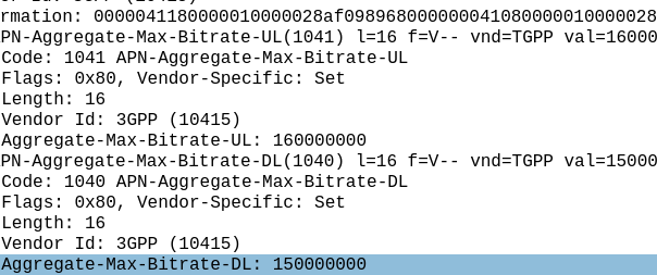
The Max-Requested-Bandwidth-DL AVP tells the PGW the max throughput allowed in bits per second. It’s a Unsigned32 so max value is 4294967294, hence the value.
But come release 15 some bright spark thought we may in the not to distant future break this barrier, so how do we go above this?
The answer was to bolt on another AVP – the “Extended-Max-Requested-BW-DL” AVP ( 554 ) was introduced, you might think that means the max speed now becomes 2x 4.295 Gbps but that’s not quite right – The units was shifted.
This AVP isn’t measuring bits per second it’s measuring kilobits per second.
So the standard Max-Requested-Bandwidth-DL AVP gives us 4.3 Gbps, while the Extended-Max-Requested-Bandwidth gives us a 4,295 Gbps.
We add the Extended-Max-Requested-Bandwidth AVP (4295 Gbps) onto the Max-Requested Bandwidth AVP (4.3 Gbps) giving us a total of 4,4299.3 Gbps.
Last year I purchased a cheap second hand Huawei macro base station – there’s lots of these on the market at the moment due to the fact they’re being replaced in many countries.
I’m using it in my lab environment, and as such the config I’ve got is very “bare bones” and basic. Keep in mind if you’re looking to deploy a Macro eNodeB in production, you may need more than just a blog post to get everything tuned and functioning properly…
In this post we’ll cover setting up a Huawei BTS3900 eNodeB from scratch, using the MML interface, without relying on the U2020 management tool.
Obviously the details I setup (IP Addressing, PLMN and RF parameters) are going to be different to what you’re configuring, so keep that in mind, where I’ve got my MME Addresses, site IDs, TACs, IP Addresses, RFUs, etc, you’ll need to substitute your own values.
A word on Cabinets
Typically these eNodeBs are shipped in cabinets, that contain the power supplies, alarm / environmental monitoring, power distribution, etc.
Early on in the setup process we’ll be setting the cabinet types we’ve got, and then later on we’ll tell the system what we have installed in which slots.
This is fine if you have a cabinet and know the type, but in my case at least I don’t have a cabinet manufactured by Huawei, just a rack with some kit mounted in it.
This is OK, but it leads to a few gotchas I need to add a cabinet (even though it doesn’t physically exist) and when I setup my RRUs I need to define what cabinet, slot and subrack it’s in, even though it isn’t in any. Keep this in mind as we go along and define the position of the equipment, that if you’re not using a real-world cabinet, the values mean nothing, but need to be kept consistent.
To begin we’ll need to setup the basics, by disabling DHCP and setting an local IP Address for the unit.
 SET DHCPSW: SWITCH=DISABLE;
 SET LOCALIP: IP="192.168.5.234", MASK="255.255.248.0";
Obviously your IP address details will be different. Next we’ll add an eNodeB function, the LMPT / UMPT can have multiple functions and multiple eNodeBs hosted on the same hardware, but in our case we’re just going to configure one:
Again, your eNodeB ID, location, site name, etc, are all going to be different, as will your location.
Next we’ll set the system to maintenance mode (MNTMODE), so we can make changes on the fly (this takes the eNB off the air, but we’re already off the air), you’ll need to adjust the start and end times to reflect the current time for the start time, and end time to be after you’re done setting all this up.
SET MNTMODE: MNTMode=INSTALL, ST=2013&09&20&15&00&00, ET=2013&09&25&15&00&00, MMSetRemark="NewSite Install";
Next we’ll set the operator details, this is the PLMN of the eNodeB, and create a new tracking area.
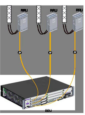
Next we’ll be setting and populating the cabinets I mentioned earlier. I’ll be telling the unit it’s inside a APM30 (Cabinet 0), and in Cabinet Number 0, Subrack 0, is a BBU3900.
 //To modify the cabinet type, run the following command:
 ADD CABINET:CN=0,TYPE=APM30;
 //Add a BBU3900 subrack, run the following command:
 ADD SUBRACK:CN=0,SRN=0,TYPE=BBU3900;
 //To configure boards and RF datas, run the following commands:
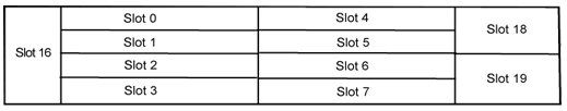
And inside the BBU3900 there’s some cards of course, and each card has as slot, as per the drawing below.
In my environment I’ve got a LMPT in slot 7, and a LBBP in Slot 3. There’s a fan and a UPEU too, so: We’ll add a board in Slot No. 7, of type LMPT, We’ll add a board in Slot No. 3, of type LBBP working on FDD, We’ll add a fan board in Slot No. 16, and a UPEU in Slot No. 18.
Huawei publish design guides for which cards should be in which slots, the general rule is that your LMPT / UMPT card goes in Slot 7, with your BBP cards (UBBP or LBBP) in slots 3, then 2, then 1, then 0. Fans and UPEUs can only go in the slots designed to fit them, so that makes it a bit easier.
Next we’ll need to setup our RRUs, for this we’ll need to setup an RRU chain, which is the Huawei term for the CPRI links and add an RRU into it:
//Modify the reference signal power.
MOD PDSCHCFG: LocalCellId=1, ReferenceSignalPwr=-81;

//Add an operator for the cell.
ADD CELLOP: LocalCellId=0, TrackingAreaId=0;

//Activate the cell.
ACT CELL: LocalCellId=1;
The Binding Support Function is used in 4G and 5G networks to allow applications to authenticate against the network, it’s what we use to authenticate for XCAP and for an Entitlement Server.
Rather irritatingly, there are two BSF addresses in use:
If the ISIM is used for bootstrapping the FQDN to use is:
bsf.ims.mncXXX.mccYYY.pub.3gppnetwork.org
But if the USIM is used for bootstrapping the FQDN is
bsf.mncXXX.mccYYY.pub.3gppnetwork.org
You can override this by setting the 6FDA EF_GBANL (GBA NAF List) on the USIM or equivalent on the ISIM, however not all devices honour this from my testing.
We recently added support in PyHSS for fixed line SIP subscribers to attach to the IMS.
Traditional telecom operators are finding their fixed line network to be a bit of a money pit, something they’re required to keep operating to meet regulatory obligations, but the switches are sitting idle 99% of the time. As such we’re seeing more and more operators move fixed line subs onto their IMS.
This new feature means we can use PyHSS to serve as the brains for a fixed network, as well as for mobile, but there’s one catch – How we authenticate subscribers changes.
Most banks of line cards in a legacy telecom switches, or IP Phones, don’t have SIM slots to allow us to authenticate, so instead we’re forced to fallback to what they do support.
Unfortunately for the most part, what is supported by these IP phones or telecom switches is SIP MD5 Digest Authentication.
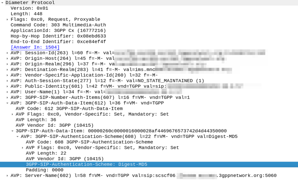
The Nonce is generated by the HSS and put into the Multimedia-Authentication-Answer, along with the subscriber’s password and sent in the clear to the S-CSCF.
The HSS then generates the the Multimedia-Auth Answer, it generates a nonce (in the 3GPP-SIP-Authenticate / 609 AVP) and sends the Subscriber’s password in the 3GPP-SIP-Authorization (610) AVP in response back to the S-CSCF.
I would have thought a better option would be for the HSS to generate the Nonce and Digest, and then the S-CSCF to just send the Nonce to the Sub and compare the returned Digest from the Sub against the expected Digest from the HSS, but it would limit flexibility (realm adaptation, etc) I guess.
The UE/UA (I guess it’s a UA in this context as it’s not a mobile) then generates its own Digest from the Nonce and sends it back to the S-CSCF via the P-CSCF.
The S-CSCF compares the received Digest response against the one it generated, and if the two match, the sub is authenticated and allowed to attach onto the network.
In the past I had my iFCs setup to look for the P-Access-Network-Info header to know if the call was coming from the IMS, but it wasn’t foolproof – Fixed line IMS subs didn’t have this header.
If you’ve ever worked in roaming, you’ll probably have had the misfortune of dealing with Transferred Account Procedures aka TAP files.
It’s used for billing a 2G GSM call right up to 5G data usage, if you use a service while roaming, somewhere in the world there’s a TAP file with your usage in it.
A brief history of TAP
TAP was originally specified by the GSMA in 1991 as a standard CDR interchange format between operators, for use in roaming scenarios.
Notice I said GSMA – Not 3GPP – This means there’s no 3GPP TS docs for this, it’s defined by the industry lobby group’s members, rather than the standards body.
So what does this actually mean? Well, if you’re MNO A and a customer from MNO B roams into your network, all the calls, SMS and data consumed by the roaming subscriber from MNO B will need to be billed to MNO B, by you, MNO A.
If a network operator wants to get paid for traffic used on their network by roaming subscribers, they’d better send out a TAP file to the roamer’s home network.
TAP is the file format generated my MNO A and sent to MNO B, containing all the usage charges that subscribers from MNO B have racked up while roaming into your network.
These are broken down into “Transactions” (CDRs), for events like making a call, connecting a PDN session and consuming data, or sending a text.
In the beginning of time, GSM provided only voice calling service. This meant that the only services a subscriber could consume while roaming was just making/receiving voice calls which were billed at the end of each month. – This meant billing was equally simple, every so often the visisted network would send the TAP files for the voice calls made by subscribers visited other networks, to the home networks, which would markup those charges, and add them onto the monthly invoice for each subscriber who was roaming.
But of course today, calling accounts for a tiny amount of usage on the network, but this happened gradually while passing through the introduction of SMS, CAMEL services, prepaid services, mobile data, etc. For all these services that could be offered, the TAP format had to evolve to handle each of these scenarios.
As we move towards a flat IP architecture, where voice calls and SMS sent while roaming are just data, TAP files for 4G and 5G networks only need to show data transactions, so the call objects, CAMEL parameters and SMS objects are all falling by the wayside.
What’s inside a TAP File
TAP uses the most beloved of formats – ASN1 to encode the data. This means it is strictly formatted and rigidly specified.
Each file contains a Sequence Number which is a monotonically increasing number, which allows the receiver to know if any files have been missed between the file that’s being currently parsed, an the previous file.
They also have a recipient and sender TADIG code, which is a code allocated by GSMA that uniquely identifies the sender and the recipient of the file.
The TAP records exist in one of two common format, Notification Records and transferBatch records.
These files are exchanged between operators, in practice this means “Dumped on an FTP server as agreed between the two”.
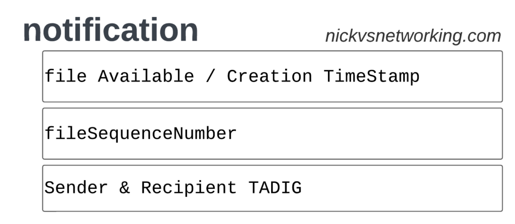
TAP Notification Records
Notifications are the simplest of TAP records and are used when there aren’t any CDRs for roaming events during the time period the TAP file covers.
These are essentially blank TAP files generated by the visited network to let the home network know it’s still there, but there are no roaming subs consuming services in that period.
Notification files are really simple, let’s take a look as one shown as JSON:
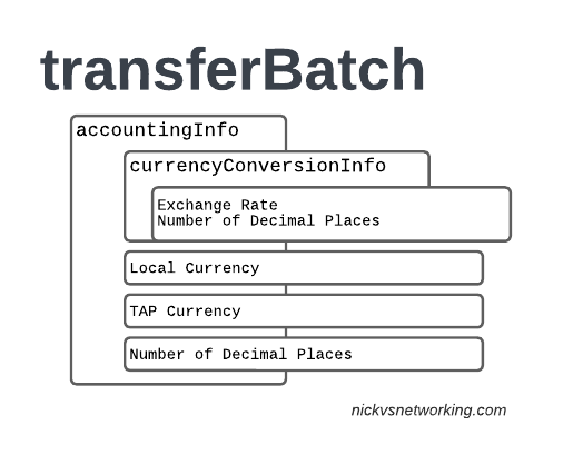
When we have services to bill and records to charge, that’s when instead we generate a transferBatch record.
It looks something like this:
There’s a lot going on in here, so let’s break it down section by section.
accountingInfo
The accountingInfo section specifies the currency, exchange rate parameters.
Keep in mind a TAP record generated by an operator in the US, would use USD, while the receiver of the file may be a European MNO dealing in EUR.
This gets even more complicated if you’re dealing with more obscure currencies where an intermediary currency is used, that’s where we bring in SDRs (“Special Drawing Right”) that map to the dollar value to be charged, kinda – the roaming agreement defines how many SDRs are in a dollar, in the example below we’re not using any, but you do see it.
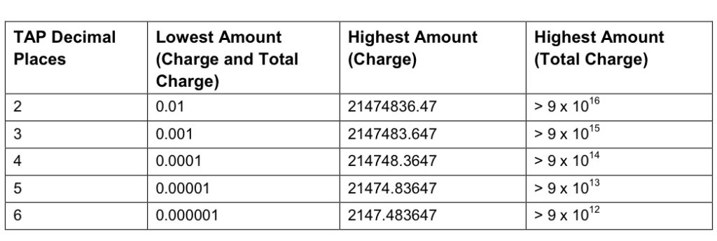
When it comes to numbers and decimal places, TAP doesn’t exactly make it easy.
Significant Digits are defined by counting the first number before the decimal point and all the numbers to the right of the decimal point, so for example the number 1.234 would be 4 significant digits (1 digit before the decimal point and 3 digits after it).
Decimal Places are not actually supported for the Value fields in the TAP file. This is tricky because especially today when roaming tariffs are quite low, these values can be quite small, and we need to represent them as an integer number. TAP defines decimal places as the number of digits after the decimal place.
When it comes to the maximum number of decimal places, this actually impacts the maximum number we can store in the field – as ASN1 strictly enforce what we put in it.
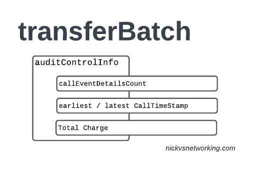
The auditControlInfo section contains the number of CDRs (callEventDetailsCount) contained in the TAP file, the timestamp of the first and last CDR in the file, the total charge and any tax charged.
All of the currency information was provided in the accountingInfo so this is just giving us our totals.
A CDR has 30 days from the time it was generated / service consumed by the roamer, to be baked into a TAP file. After this we can no longer charge for it, so it’s important that the earliestCallTimeStamp is not more than 30 days before the fileCreationTimeStamp seen in batchControlInfo.
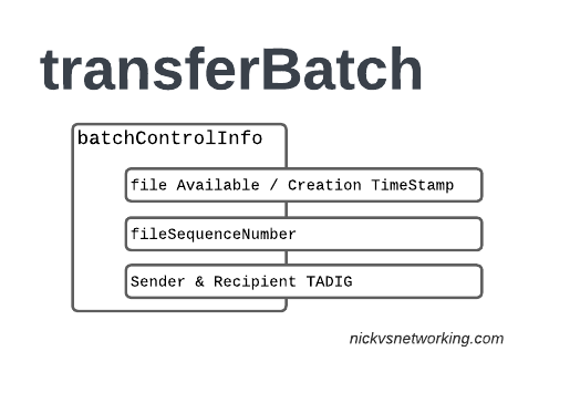
batchControlInfo
The batchControlInfo section specifies the time the TAP file became available for transfer, the time the file was created (usually the same), the sequence number and the sender / recipient TADIG codes.
As mentioned earlier, we track sequence number so the receiver can know if a TAP file has been missed; for example if you’ve got TAP file 1 and TAP file 3 comes in, you can determine you’ve missed TAP file 2.
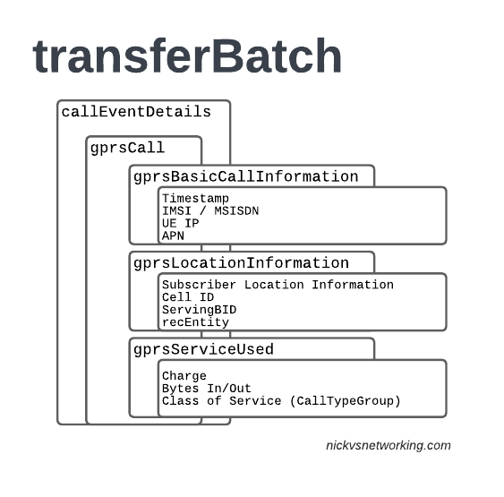
Now we’re getting to the meat & potatoes of our TAP record, the CDRs themselves.
In LTE networks these are just records of data consumption, so let’s take a look inside the gprsCall records under callEventDetails:
In the gprsBasicCallInformation we’ve got as the name suggests the basic info about the data usage event. The time when the session started, the charging ID, the IMSI and the MSISDN of the subscriber to charge, along with their IP and the APN used.
Next up we have the gprsLocationInformation – rates and tariffs may be set based on the location of the subscriber, so we need to identify the area the sub was using the services to select correct tariff / rate for traffic in this destination.
The recEntity is the index number of the SGW / PGW used for the transaction (more on that later).
Next we have the gprsServiceUsed which, again as the name suggests, details the services used and the charge.
chargeDetailList contains the charged data (Made up of dataVolumeIncoming + dataVolumeOutgoing) and the cost.
The chargeableUnits indicates the actual data consumed, however most roaming agreements will standardise on some level of rounding, for example rounding up to the nearest Kilobyte (1024 bytes), so while a sub may consume 1025 bytes of data, they’d be billed for 2045 bytes of data. The data consumed is indicated in the chargeableUnits which indicates how much data was actually consumed, before any rounding policies where applied, while the amount that is actually charged (When taking into account rounding policies) isindicated inside Charged Units.
In the example below data usage is rounded up to the nearest 1024 bytes, 134390 bytes rounds up to the nearest 1024 gives you 135168 bytes.
As this is data we’re talking bytes, but not all bytes are created equal!
VoLTE traffic, using a QCI1 bearer is more valuable than QCI 9 cat videos, and TAP records take this into account in the Call Type Groups, each of which has a different price – Call Type Level 1 indicates the type of traffic, for S8 Home Routed LTE Traffic this is 10 (HGGSN/HP-GW), while Call Type Level 2 indicates the type of traffic as mapped to QCI values:
So Call Type Level 2 set to 20 indicates that this is “20 Unspecified/default LTE QCIs”, and Call Type Level 3 can be set to any value based on a defined inter-operator tariff.
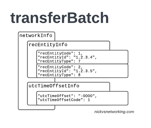
recEntityType 7 means a PGW and contains the IP of the PGW in the Home PLMN, while recEntityType 8 means SGW and is the SGW in the Visited PLMN.
So this means if we reference recEntityCode 2 in a gprsCall, that we’re referring to an SGW at 1.2.3.5.
Lastly also got the utcTimeOffsetInfo to indicate the timezones used and assign a unique code to it.
Using the Records
We as humans? These records aren’t meant for us.
They’re designed to be generated by the Visited PLMN and sent to to the home PLMN, which ingests it and pays the amount specified in the time agreed.
Generally this is an FTP server that the TAP records get dumped into, and an automated bank transfer job based on the totals for the TAP records.
Testing of the TAP records is called “TADIG Testing” and it’s something we’ll go into another day, but in essence it’s validating that the output and contents of the files meet what both operators think is the contract pricing and specifications.
So that’s it! That’s what’s in a TAP record, what it does and how we use it!
GSMA are introducing BCE – Billing & Charging Evolution, a new standard, designed to last for the next 30+ years like TAP has. It’s still in its early days, but that’s the direction the GSMA has indicated it would like to go.
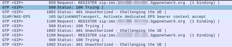
Everything was working on the IMS, then I go to bed, the next morning I fire up the test device and it just won’t authenticate to the IMS – The S-CSCF generated a 401 in response to the REGISTER, but the next REGISTER wouldn’t pass.
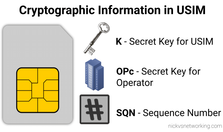
When we generate the vectors (for IMS auth and standard auth) one of the inputs to generate the vectors is the Sequence Number or SQN.
This SQN ticks over like an odometer for the number of times the SIM / HSS authentication process has been performed.
There is some leeway in the SQN – It may not always match between the SIM and the HSS and that’s to be expected. When the MME sends an Authentication-Information-Request it can ask for multiple vectors so it’s got some in reserve for the next time the subscriber attaches, and that’s allowed.
But there are limits to how far out our SQN can be, and for good reason – One of the key purposes for the SQN is to protect against replay attacks, where the same vector is replayed to the UE. So the SQN on the HSS can be ahead of the SIM (within reason), but it can’t be behind – Odometers don’t go backwards.
So the issue was with the SQN on the SIM being out of Sync with the SQN in the IMS, how do we know this is the case, and how do we fix this?
Well there is a resync mechanism so the SIM can securely tell the HSS what the current SQN it is using, so the HSS can update it’s SQN.
When verifying the AUTN, the client may detect that the sequence numbers between the client and the server have fallen out of sync. In this case, the client produces a synchronization parameter AUTS, using the shared secret K and the client sequence number SQN. The AUTS parameter is delivered to the network in the authentication response, and the authentication can be tried again based on authentication vectors generated with the synchronized sequence number.
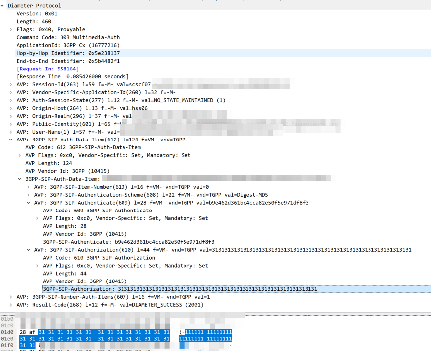
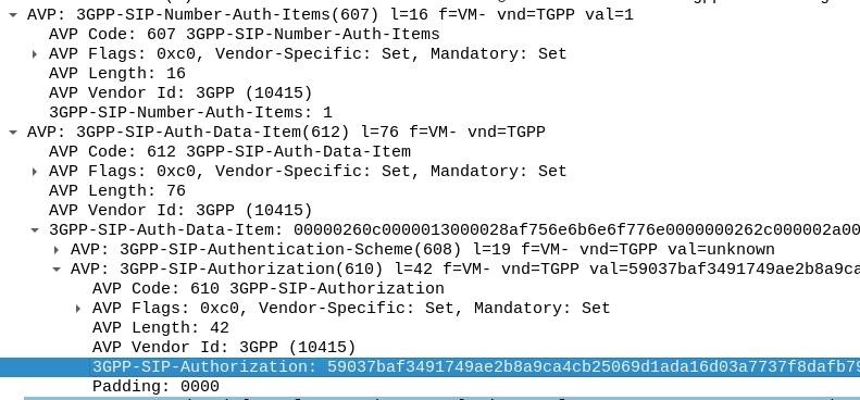
In our example we can tell the sub is out of sync as in our Multimedia Authentication Request we see the SIP-Authorization AVP, which contains the AUTS (client synchronization parameter) which the SIM generated and the UE sent back to the S-CSCF. Our HSS can use the AUTS value to determine the correct SQN.
SIP-Authorization AVP in the Multimedia Authentication Request means the SQN is out of Sync and this AVP contains the RAND and AUTN required to Resync
Note: The SIP-Authorization AVP actually contains both the RAND and the AUTN concatenated together, so in the above example the first 32 bytes are the AUTN value, and the last 32 bytes are the RAND value.
So the HSS gets the AUTS and from it is able to calculate the correct SQN to use.
Then the HSS just generates a new Multimedia Authentication Answer with a new vector using the correct SQN, sends it back to the IMS and presto, the UE can respond to the challenge normally.
Misunderstood, under appreciated and more capable than people give it credit for, is our PCRF.
But what does it do?
Most folks describe the PCRF in hand wavy-terms – “it does policy and charging” is the answer you’ll get, but that doesn’t really tell you anything.
So let’s answer it in a way that hopefully makes some practical sense, starting with the acronym “PCRF” itself, it stands for Policy and Charging Rules Function, which is kind of two functions, one for policy and one for rules, so let’s take a look at both.
Policy
In cellular world, as in law, policy is the rules.
For us some examples of policy could be a “fair use policy” to limit customer usage to acceptable levels, but it can also be promotional packages, services like “free Spotify” packages, “Voice call priority” or “unmetered access to Nick’s Blog and maximum priority” packages, can be offered to customers.
All of these are examples of policy, and to make them work we need to target which subscribers and traffic we want to apply the policy to, and then apply the policy.
Charging Rules
Charging Rules are where the policy actually gets applied and the magic happens.
It’s where we take our policy and turn it into actionable stuff for the cellular world.
Let’s take an example of “unmetered access to Nick’s Blog and maximum priority” as something we want to offer in all our cellular plans, to provide access that doesn’t come out of your regular usage, as well as provide QCI 5 (Highest non dedicated QoS) to this traffic.
To achieve this we need to do 3 things:
Profile the traffic going to this website (so we capture this traffic and not regular other internet traffic)
Charge it differently – So it’s not coming from the subscriber’s regular balance
Up the QoS (QCI) on this traffic to ensure it’s high priority compared to the other traffic on the network
So how do we do that?
Profiling Traffic
So the first step we need to take in providing free access to this website is to filter out traffic to this website, from the traffic not going to this website.
Let’s imagine that this website is hosted on a single machine with the IP 1.2.3.4, and it serves traffic on TCP port 443. This is where IPFilterRules (aka TFTs or “Traffic Flow Templates”) and the Flow-Description AVP come into play. We’ve covered this in the past here, but let’s recap:
IPFilterRules are defined in the Diameter Base Protocol (IETF RFC 6733), where we can learn the basics of encoding them,
They take the format:
action dir proto from src to dst
The action is fairly simple, for all our Dedicated Bearer needs, and the Flow-Description AVP, the action is going to be permit. We’re not blocking here.
The direction (dir) in our case is either in or out, from the perspective of the UE.
Next up is the protocol number (proto), as defined by IANA, but chances are you’ll be using 17 (UDP) or 6 (TCP).
The from value is followed by an IP address with an optional subnet mask in CIDR format, for example from 10.45.0.0/16would match everything in the 10.45.0.0/16 network.
Following from you can also specify the port you want the rule to apply to, or, a range of ports.
Like the from, the tois encoded in the same way, with either a single IP, or a subnet, and optional ports specified.
And that’s it!
So let’s create a rule that matches all traffic to our website hosted on 1.2.3.4 TCP port 443,
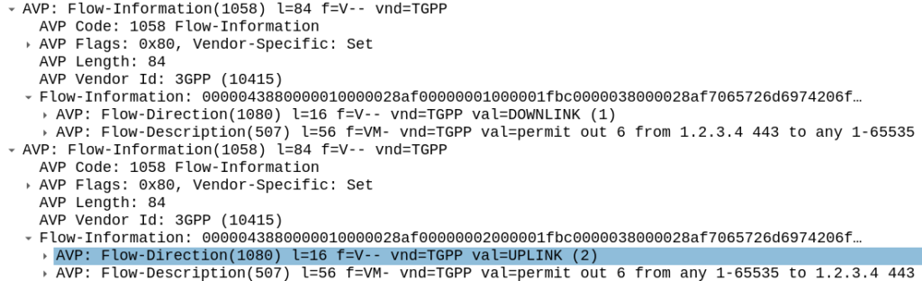
permit out 6 from 1.2.3.4 443 to any 1-65535
permit out 6 from any 1-65535 to 1.2.3.4 443
All this info gets put into the Flow-Information AVPs:
With the above, any traffic going to/from 1.23.4 on port 443, will match this rule (unless there’s another rule with a higher precedence value).
Charging Actions
So with our traffic profiled, the next question is what actions are we going to take, well there’s two, we’re going to provide unmetered access to the profiled traffic, and we’re going to use QCI 4 for the traffic (because you’ll need a guaranteed bit rate bearer to access!).
Charging-Group for Profiled Traffic
To allow for Zero Rating for traffic matching this rule, we’ll need to use a different Rating Group.
Let’s imagine our default rating group for data is 10000, then any normal traffic going to the OCS will use rating group 10000, and the OCS will apply the specific rates and policies based on that.
Rating Groups are defined in the OCS, and dictate what rates get applied to what Rating Groups.
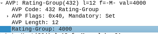
For us, our default rating group will be charged at the normal rates, but we can define a rating group value of 4000, and set the OCS to provide unlimited traffic to any Credit-Control-Requests that come in with Rating Group 4000.
This is how operators provide services like “Unlimited Facebook” for example, a Charging Rule matches the traffic to Facebook based on TFTs, and then the Rating Group is set differently to the default rating group, and the OCS just allows all traffic on that rating group, regardless of how much is consumed.
Inside our Charging-Rule-Definition, we populate the Rating-Group AVP to define what Rating Group we’re going to use.
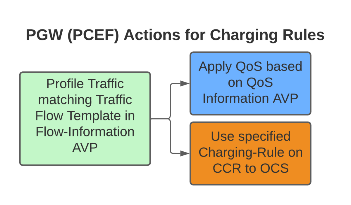
Setting QoS for Profiled Traffic
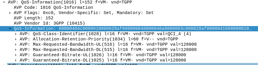
The QoS Description AVP defines which QoS parameters (QCI / ARP / Guaranteed & Maximum Bandwidth) should be applied to the traffic that matches the rules we just defined.
As mentioned at the start, we’ll use QCI 4 for this traffic, and allocate MBR/GBR values for this traffic.
Putting it Together – The Charging Rule
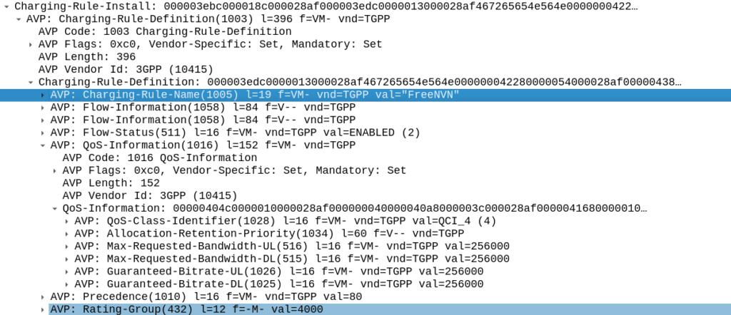
So with our TFTs defined to match the traffic, our Rating Group to charge the traffic and our QoS to apply to the traffic, we’re ready to put the whole thing together.
So here it is, our “Free NVN” rule:
I’ve attached a PCAP of the flow to this post.
In our next post we’ll talk about how the PGW handles the installation of this rule.
One day recently I was messing with the XCAP server, trying to set the Call Forward timeout. In the process I triggered the UE to send a USSD request to the IMS.
Huh, I thought, “I wonder how hard it would be to build a USSD Gateway for our IMS?”, and this my friends, is the story of how I wasted a good chunk of my weekend trying (and failing) to add support for USSD.
You might be asking “Who still uses USSD?” – The use cases for USSD are pretty thin on the ground in this day and age, but I guess balance query, and uh…
But this is the story of what I tried before giving up and going outside…
Routing
First I’d need to get the USSD traffic towards the USSD Gateway, this means modifying iFCs. Skimming over the spec I can see the Recv-Info: header for USSD traffic should be set to “g.3gpp.ussd” so I knocked up an iFC to match that, and route the traffic to my dev USSD Gateway, and added it to the subscriber profile in PyHSS:
Easy peasy, now we have the USSD requests hitting our USSD Gateway.
The Response
I’ll admit that I didn’t jump straight to the TS doc from the start.
The first place I headed was Google to see if I could find any PCAPs of USSD over IMS/SIP.
And I did – Restcomm seems to have had a USSD product a few years back, and trawling around their stuff provided some reference PCAPs of USSD over SIP.
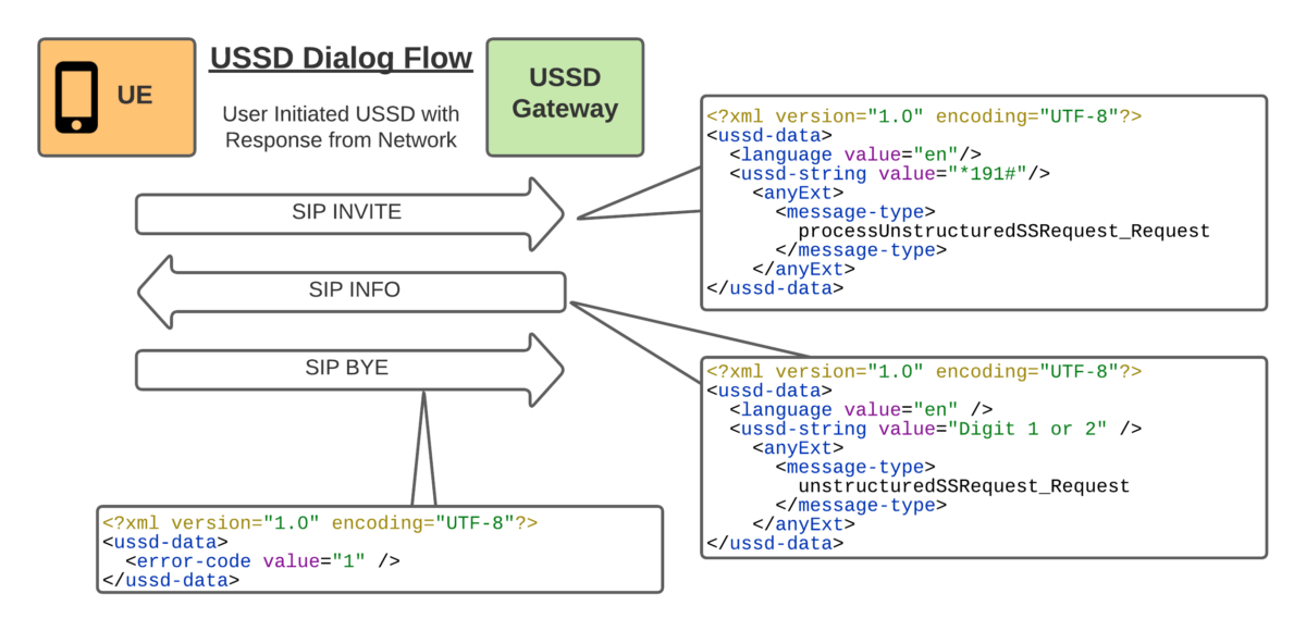
So the flow seemed pretty simple, SIP INVITE to set up the session, SIP INFO for in-dialog responses and a BYE at the end.
With all the USSD guts transferred as XML bodies, in a way that’s pretty easy to understand.
Being a Kamailio fan, that’s the first place I started, but quickly realised that SIP proxies, aren’t great at acting as the UAS.
So I needed to generate in-dialog SIP INFO messages, so I turned to the UAC module to generate the SIP INFO response.
My Kamailio code is super simple, but let’s have a look:
request_route {

        xlog("Request $rm from $fU");

        if(is_method("INVITE")){
                xlog("USSD from $fU to $rU (Emergency number) CSeq is $cs ");
                sl_reply("200", "OK Trying USSD Phase 1");      #Generate 200 OK
                route("USSD_Response"); #Call USSD_Response route block
                exit;
        }
}

route["USSD_Response"]{
        xlog("USSD_Response Route");
        #Generate a new UAC Request
        $uac_req(method)="INFO";
        $uac_req(ruri)=$fu;     #Copy From URI to Request URI
        $uac_req(furi)=$tu;     #Copy To URI to From URI
        $uac_req(turi)=$fu;     #Copy From URI to To URI
        $uac_req(callid)=$ci;   #Copy Call-ID
                                #Set Content Type to 3GPP USSD
        $uac_req(hdrs)=$uac_req(hdrs) + "Content-Type: application/vnd.3gpp.ussd+xml\r\n";
                                #Set the USSD XML Response body
        $uac_req(body)="<?xml version='1.0' encoding='UTF-8'?>
        <ussd-data>
                <language value=\"en\"/>
                <ussd-string value=\"Bienvenido. Seleccione una opcion: 1 o 2.\"/>
        </ussd-data>";
        $uac_req(evroute)=1;    #Set the event route to use on return replies
        uac_req_send();         #Send it!
}
So the UAC module generates the 200 OK and sends it back.
“That was quick” I told myself, patting myself on the back before trying it out for the first time.
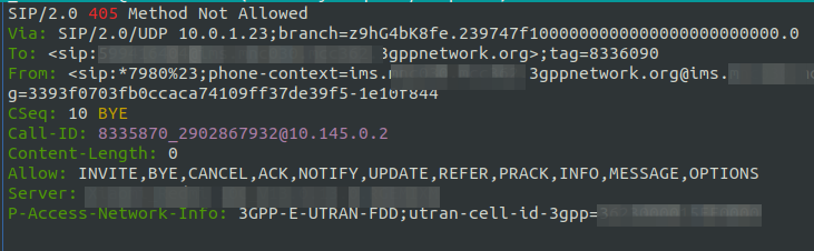
Huston, we have a problem – Although the Call-ID is the same, it’s not an in-dialog response as the tags aren’t present, this means our UE send back a 405 to the SIP INFO.
Right. Perhaps this is the time to read the Spec…
Okay, so the SIP INFO needs to be in dialog. Can we do that with the UAC module? Perhaps not…
But alas real life came back to rear its ugly head, and this adventure will have to continue another day…
Update: Thanks to a kindly provided PCAP I now know what I was doing wrong, and so we’ll soon have a follow up to this post named “Successes in cobbling together a USSD Gateway” just as soon as I have a weekend free.
NB-IoT introduces support for NIDD – Non-IP Data Delivery (NIDD) which is one of the cool features of NB-IoT that’s gaining more widespread adoption.
Let’s take a deep dive into NIDD.
The case against IP for IoT
In the over 40 years since IP was standardized, we’ve shoehorned many things onto IP, but IP was never designed or optimized for low power, low throughput applications.
For the battery life of an IoT device to be measured in years, it has to be very selective about what power hungry operations it does. Transmitting data over the air is one of the most power-intensive operations an IoT device can perform, so we need to do everything we can to limit how much data is sent, and how frequently.
Use Case – NB-IoT Tap
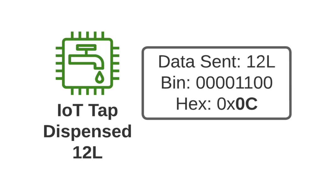
Let’s imagine we’re launching an IoT tap that transmits information about water used, as part of our revolutionary new “Water as a Service” model (WaaS) which removes the capex for residents building their own water treatment plant in their homes, and instead allows dynamic scaling of waterloads as they move to our new opex model.
If I turn on the tap and use 12L of water, when I turn off the tap, our IoT tap encodes the usage onto a single byte and sends the usage information to our rain-cloud service provider.
So we’re not constantly changing the batteries in our taps, we need to send this one byte of data as efficiently as possible, so as to maximize the battery life.
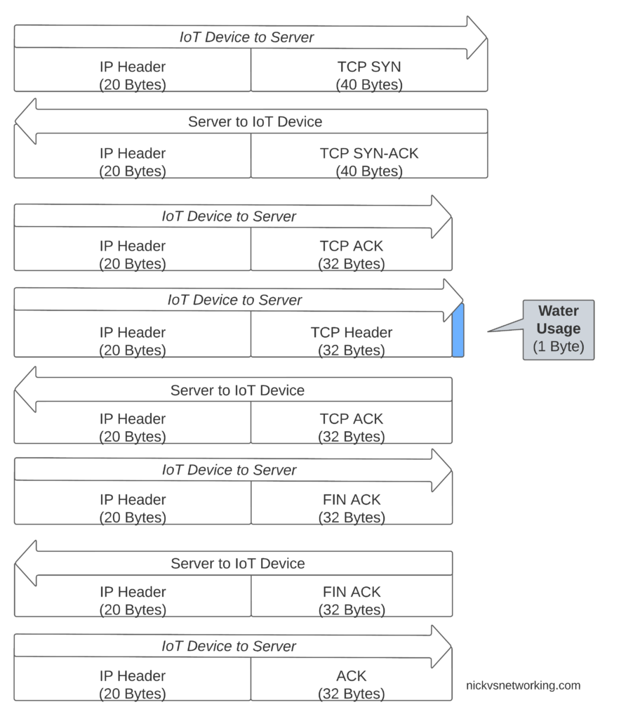
If we were to transport our data on TCP, well we’d need a 3 way handshake and several messages just to transmit the data we want to send.
Let’s see how our one byte of data would look if we transported it on TCP.
That sliver of blue in the diagram is our usage component, the rest is overhead used to get it there. Seems wasteful huh?
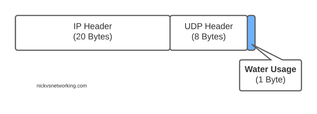
Sure, TCP isn’t great for this you say, you should use UDP! But even if we moved away from TCP to UDP, we’ve still got the IPv4 header and the UDP header wasting 28 bytes.
For efficiency’s sake (To keep our batteries lasting as long as possible) we want to send as few messages as possible, and where we do have to send messages, keep them very short, so IP is not a great fit here.
Enter NIDD – Non-IP Data Delivery.
Through NIDD we can just send the single hex byte, only be charged for the single hex byte, and only stay transmitting long enough to send this single byte of hex (Plus the NBIoT overheads / headers).
Compared to UDP transport, NIDD provides us a reduction of 28 bytes of overhead for each message, or a 96% reduction in message size, which translates to real power savings for our IoT device.
In summary – the more sending your device has to do, the more battery it consumes. So in a scenario where you’re trying to maximize power efficiency to keep your batter powered device running as long as possible, needing to transmit 28 bytes of wasted data to transport 1 byte of usable data, is a real waste.
Delivering the Payload
NIDD traffic is transported as raw hex data end to end, this means for our 1 byte of water usage data, the device would just send the hex value to be transferred and it’d pop out the other end.
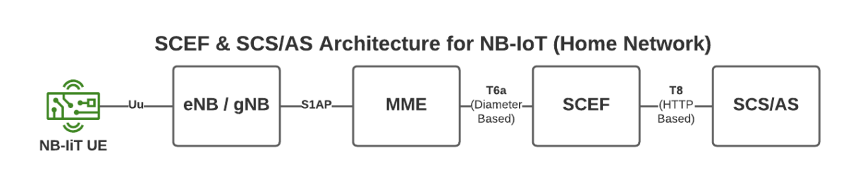
To support this we introduce a new network element called the SCEF –Service Capability Exposure Function.
From a developer’s perspective, the SCEF is the gateway to our IoT devices. Through the RESTful API on the SCEF (T8 API), we can send and receive raw hex data to any of our IoT devices.
When one of our Water-as-a-Service Taps sends usage data as a hex byte, it’s the software talking on the T8 API to the SCEF that receives this data.
Data of course needs to be addressed, so we know where it’s coming from / going to, and T8 handles this, as well as message reliability, etc, etc.
This is a telco blog, so we should probably cover the MME connection, the MME talks via Diameter to the SCEF. In our next post we’ll go into these signaling flows in more detail.
If you’re wondering what the status of Open Source SCEF implementations are, then you may have already guessed I’m working on one!
Hopefully by now you’ve got a bit of an idea of how NIDD works in NB-IoT, and in our next posts we’ll dig deeper into the flows and look at some PCAPs together.