SMSc can send an SRI-for-SM, and if the subscriber is absent, the response can include the informServiceCenter message, which lets the SMSc know if it will get sent an alertServiceCentre message when the subscriber comes back online (sends an UpdateLocation).
This means that the SMSc can be notified when it can deliver the message to the subscriber.
It’s got a bunch of flags, which equate to:
sc-AddressNotIncluded means the service center address from the SRI-for-SM was not included in the Message Waiting Data file (and therefore will not get notified via AlertSC when the subscriber comes back online).
If it’s sc-AddressNotIncluded is set to False it means that the service center address has been added to the Message Waiting Data file, so will get an alertServiceCenter message when the sub comes back online (Double negative).
mnrf-Set means Mobile subscriber Not Reachable (Not registered on any MSC)
mcef-Set means Memory Capacity Exceeded Flag is set as the HLR has run out of memory in the Message Waiting Data file and cannot store any more data (So you won’t get notified via AlertSC when the subscriber comes back online)
mnrg-Set is for Mobile subscriber Not Reachable for GPRS (When using SGSN delivery is not registered for packet service).
mnr5g-Set means the SC will get notified when the subscriber becomes reachable from 5G serving nodes.
mnr5gn3g is a mystery – The only references to it I can find are in the ASN1 spec (hence why Wireshark decodes it) but as to its purpose, I can only guess.
CAMEL is primarily focused on charging for Voice & SMS services, as data generally uses Diameter, so it’s voice and SMS we’ll focus on.
CAMEL is spoken between the MSC (gsmSSF) and the OCS (gsmSCF).
Basic Call State Model
CAMEL is closely related to the Intelligent Network stuff on the 1980s, and steals a lot of it’s ideas from there, unfortunately if you’re to read the CAMEL standard it also implies you were involved in IN stuff and had been born at that point, alas I was neither.
So the key to understanding CAMEL is the Basic Call State Model (BCSM) which is a model of all the different states a call can be in, such as ringing, answered, abandoned, call failed, etc, etc.
Over CAMEL, our OCS can be told by the MSC when a certain event happens; the MSC can tell the OCS, that the call has changed state. For example a BCSM event might indicate the call has hung up, is ringing, cancelled, etc.
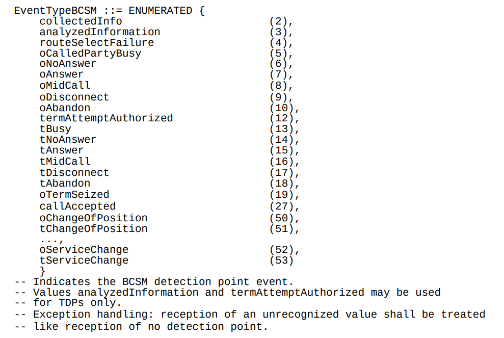
Below is the list of all the valid BCSM states:
List of BCSM states for events
Basic MO Call with CAMEL
Our subscriber makes an outbound call.
Based on the data the MSC has in it from the HLR, it knows that we should use CAMEL for this call, and it has the SCCP Address of the OCS (gsmSCF) it needs to send the CAMEL messages to.
So the MSC sends an InitialDP message to the OCS (via it’s Global Title Address) to Authorize the call that the user is trying to make.
This is like any other Authorization step for an OCS, which allows the OCS to authorize the call by checking the subscriber is valid, check if they’re allowed to call that destination and they’ve got the balance to do so, etc.
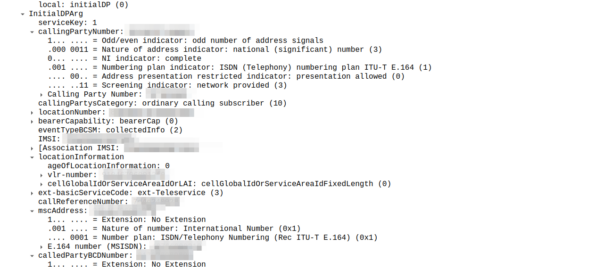
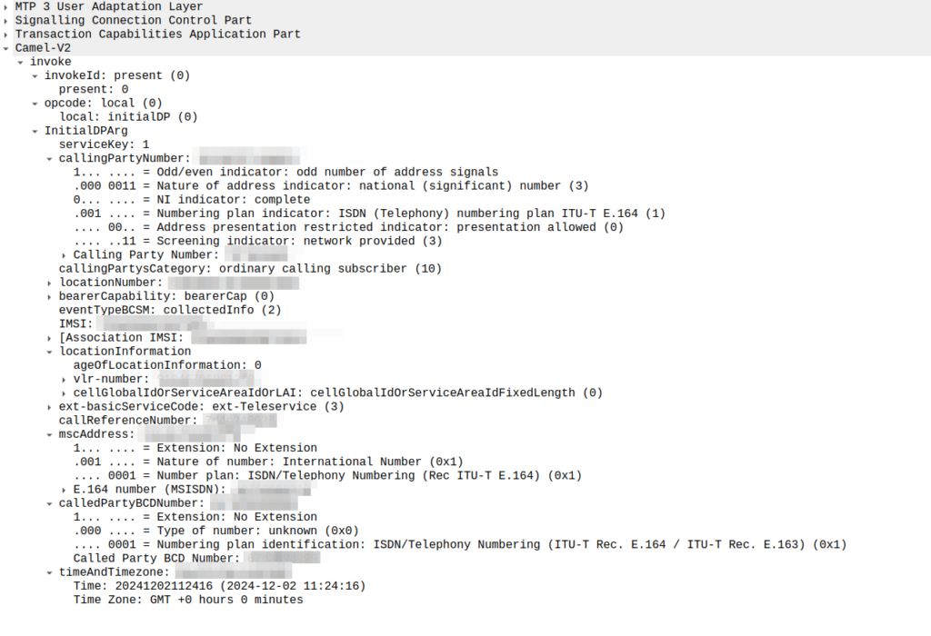
initialDP message from an MSC to an OCS
The initialDP (Initial Detection Point) is telling our OCS all about the call event that’s being requested, who’s calling, what number they’ve dialed, where they are in the network (of note especially if they’re roaming), etc, etc.
Generally the OCS also uses this message as a chance to subscribe to BCSM Events using RequestReportBCSMEventArg so the OCS will get notified by the MSC when the state of the call changes. This means the MSC will tell us when the state of the call changes; events like the call getting answered, disconnected, etc. This is critical so we know when the call gets answered and hung-up, so we can charge correctly.
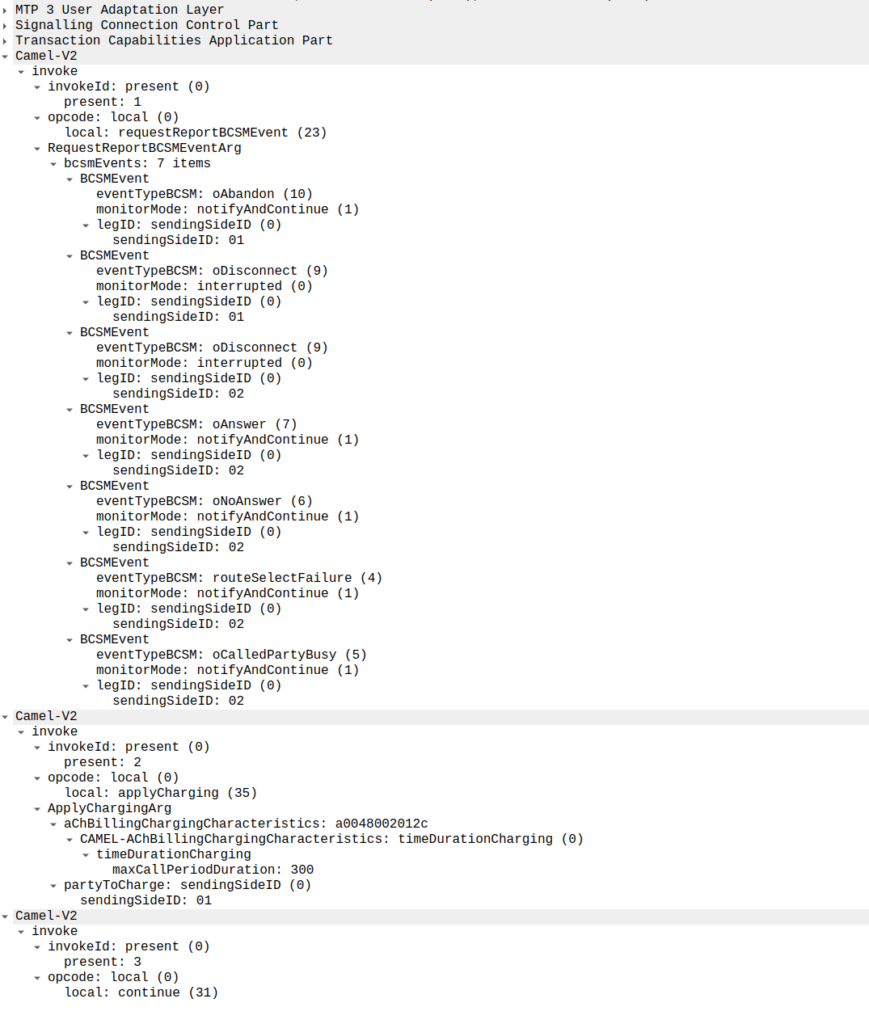
In the below example, as well as sending the Continue and RequestReportBCSMEventArg the OCS is also setting the ChargingArgs for this call, so the MSC knows who to charge (the caller) set via sendingSide and that the MSC must send an Apply Charging Report (ACR) messages every 300 units (1 unit = 100 ms, so a value of 300 = 300 x 100 milliseconds = 30 seconds) so the OCS keeps track of what’s going on.
continue sent by the OCS to the MSC, also including reportBCSMEvent and applyCharging messages
Or in a slightly less appropriate analogy but easier to understand for SIP folks, the InitialDP is sent for INVITE and the 180 RINGING is sent once the continue message is received.
Call is Answered
So at this stage our call can start to ring.
As we’ve subscribed to BCSM events in our last message, the MSC is going to tell us when the call gets answered or the call times out, is abandoned or the sun burns out.
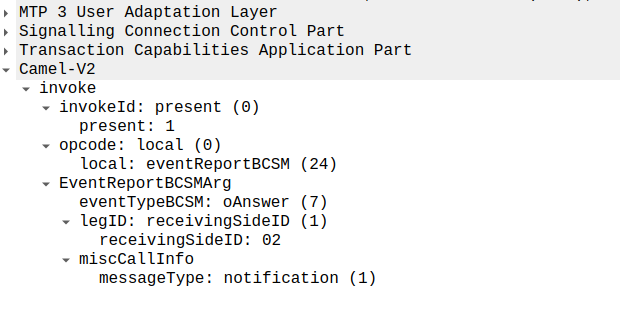
The MSC provides this info a eventReportBCSM, which is very simple and just tells us the event that’s been triggered, in the example below, the call was answered.
eventReportBCSM from MSC to OCS
These eventReportBCSM are informational from the MSC to the OCS, so the OCS doesn’t need to send anything back, but the OCS does need to mark the call as answered so it can start timing the call.
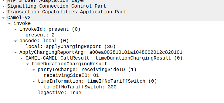
At this stage, the call is connected and our two parties are talking, but our MSC has been told it needs to send us applyChargingReports every 30 seconds (due to the value of 300 in maxCallPeriodDuration) after the call was connected, so the MSC sends the OCS it’s first applyChargingReport 30 seconds after the call was answered:
applyChargingReport sent by the MSC to the OCS every reporting period
We can calculate the duration of the call so far based on the time of the eventReportBCSM, then the OCS must make a decision of if it should allow the call to continue or not.
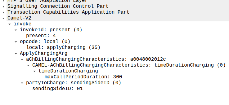
For simplicity’s sake, let’s imagine we’re still got a balance in the OCS and the OCS wants the call to continue, the OCS send back an applyCharging message to the MSC in response, and includes the current allowed maxCallPeriodDuration, keeping in mind the value is x100 and in nanoseconds (so this is 30 seconds).
applyCharging from the OCS back to the MSC
Perfect, our call is good to go for another 30 more seconds, son in 30 seconds we’ll get another ACR messages from MSC to the OCS to keep it abreast of what’s going on.
Now one of two things is going to happen, either subscriber is going to burn through all of their minutes, and get their call cutoff, or the call will end while they’ve still got balance, let’s look at both scenarios.
Normal Hangup Scenario
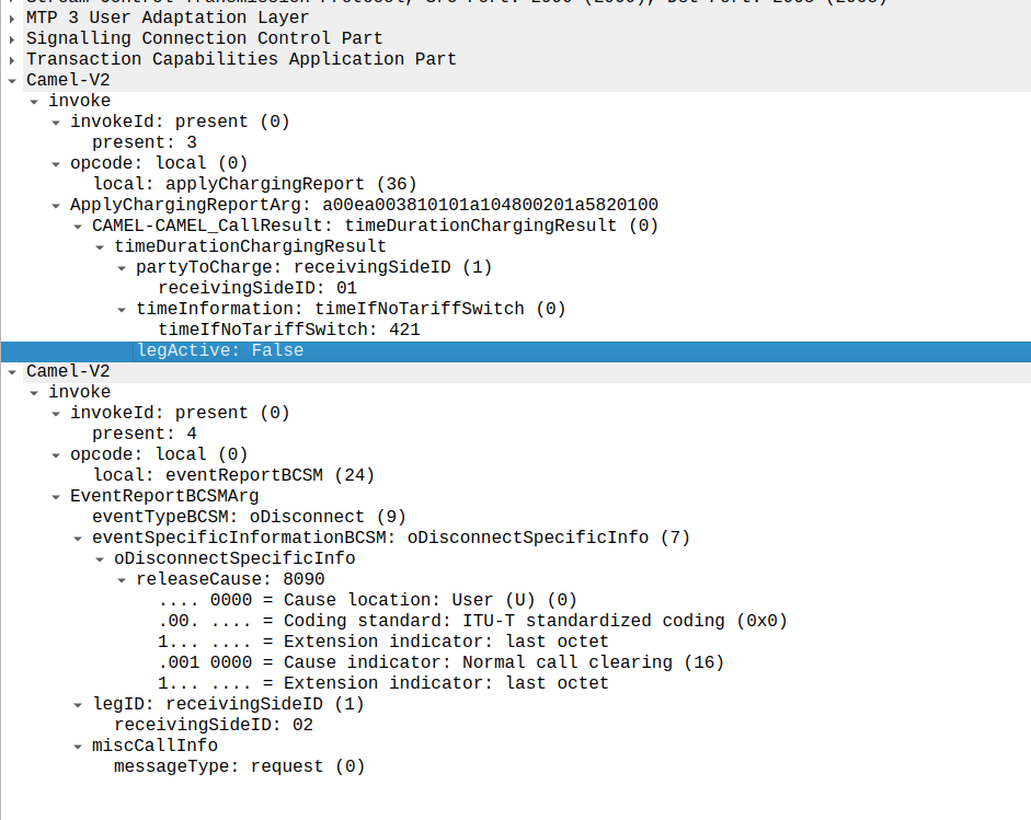
When the call ends, we get an applyChargingReport from the MSC to the OCS.
As we’ve subscribed to reportBCSMEvent we get both the applyChargingReport with legActive: False` so we know the call has hungup, and we’ve got an event report to tell us more about the event, in this case a hangup from the Originating Side.
reportBCSMEvent and applyChargingReport Sent by the MSC to the OCS to indicate the call has ended, note the legActive flag is now false
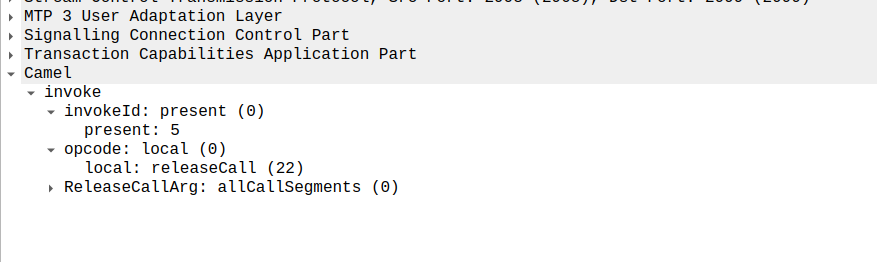
Lastly the OCS confirms by sending a releaseCall to the MSC, to indicate all legs should now terminate.
releaseCall Sent by OCS to MSC at the very end
So that’s it!
Obviously there are other flows, such as running out of balance mid-call, rejecting a call, SMS and PBX / VPN services that rely on CAMEL, but hopefully you now understand the basics of how CAMEL based charging looks and works.
If you’re looking for a CAMEL capable OCS or a CAMEL to Diameter or API gateway, get in touch!
If you’ve ever received an SMS from your operator, and the sender was the Operator name for example, you may be left wondering how it’s done.
In IMS you’d think this could be quite simple – You’d set the From header to be the name rather than the MSISDN, but for most SMSoIP deployments, the From header is ignored and instead the c header inside the SMS body is used.
So how do we get it to show text?
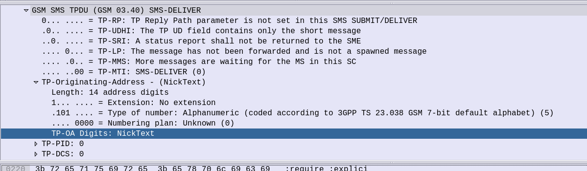
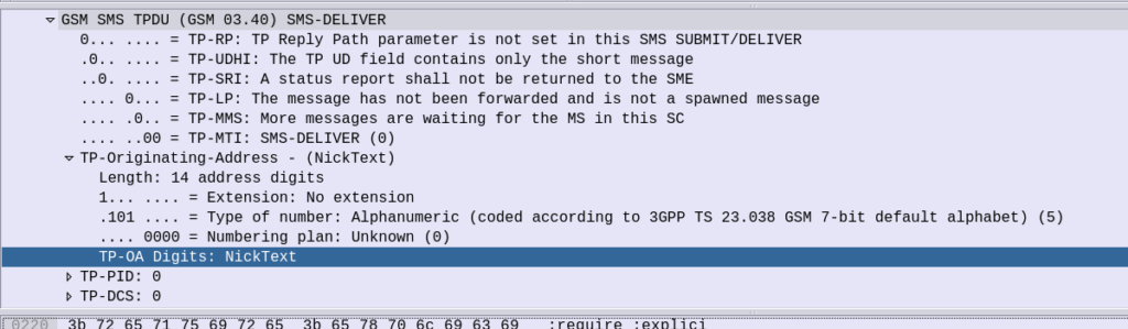
Well the TP-Originating address has the “Type of Number” (ToN) field which is typically set to International/National, but value 5 allows for the Digits to instead be alphanumeric characters.
GSM 7 bit encoding on the text in the TP-Originating Address digits and presto, you can send SMS to subscribers where the message shows as From an alphanumeric source.
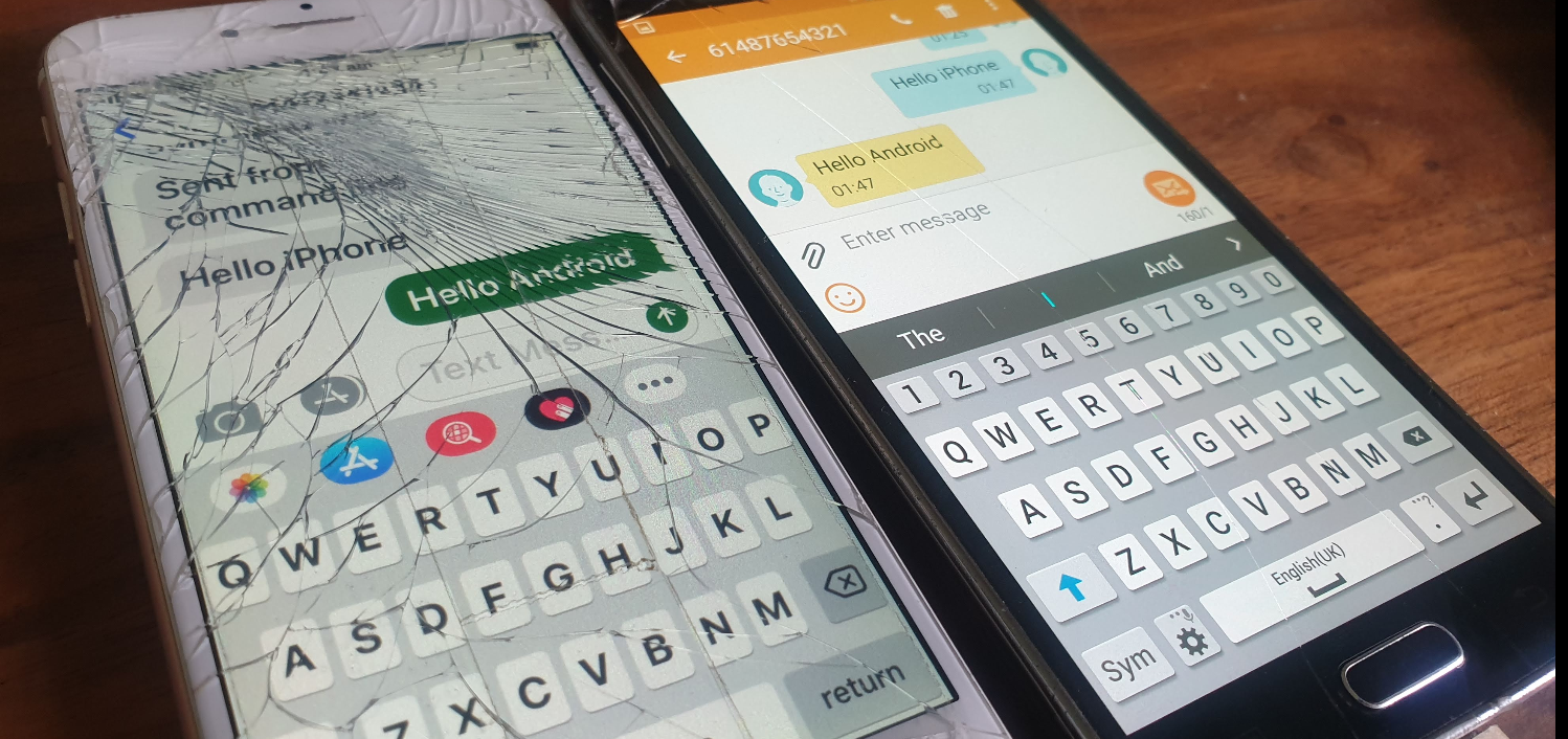
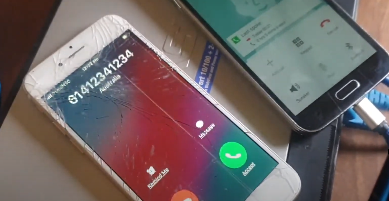
On Android SMSs received from alphanumeric sources cannot be responded to (“no more “DO NOT REPLY TO THIS MESSAGE” at the end of each text), but on iOS devices you can respond, but if I send an SMS from “Nick” the reply from the subscriber using the iPhone will be sent to MSISDN 6425 (Nick on the telephone keypad).
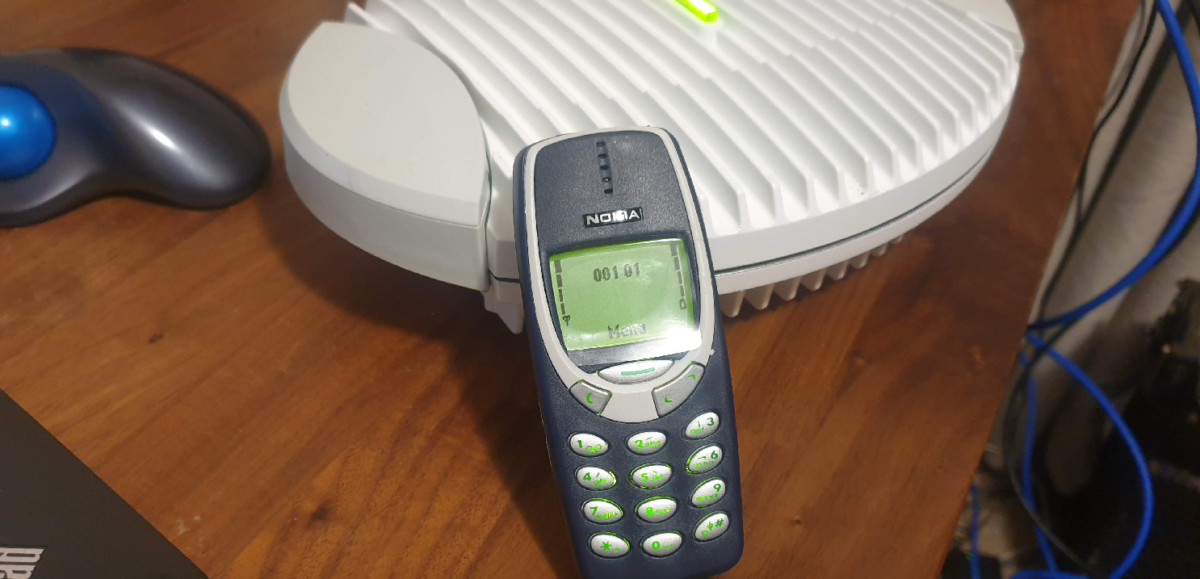
Unstructured Supplementary Service Data or “USSD” is the stack used in Cellular Networks to offer interactive text based menus and systems to Subscribers.
If you remember topping up your mobile phone credit via a text menu on your flip phone, there’s a good chance that was USSD*.
For a period, USSD Services provided Sporting Scores, Stock Prices and horoscopes on phones and networks that were not enabled for packet data.
Unlike plain SMS-PP, USSD services are transaction stateful, which means that there is a session / dialog between the subscriber and the USSD gateway that keeps track of the session and what has happened in the session thus far.
T-Mobile website from 2003 covering the features of their USSD based product at the time
Today USSD is primarily used in the network at times when a subscriber may not have balance to access packet data (Internet) services, so primarily is used for recharging with vouchers.
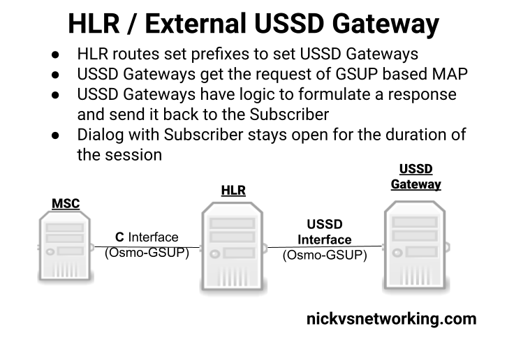
Osmocom’s HLR (osmo-hlr) has an External USSD interface to allow you to define the USSD logic in another entity, for example you could interface the USSD service with a chat bot, or interface with a billing system to manage credit.
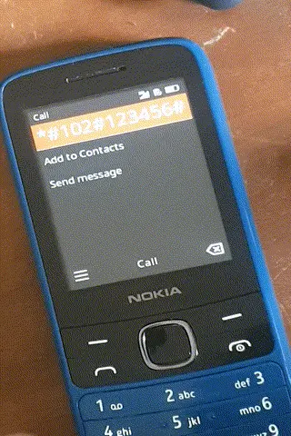
Using the example code provided I made a little demo of how the service could be used:
Communication between the USSD Gateway and the HLR is MAP but carried GSUP (Rather than the full MTP3/SCCP/TCAP layers that traditionally MAP stits on top of), and inside the HLR you define the prefixes and which USSD Gateway to route them to (This would allow you to have multiple USSD gateways and route the requests to them based on the code the subscriber sends).
(I had hoped to make a Python example and actually interface it with some external systems, but another day!)
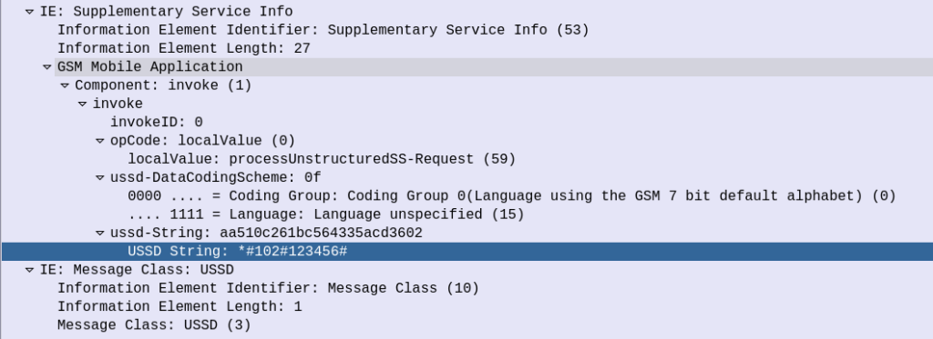
The signaling is fairly straight forward, when the subscriber kicks off the USSD request, the HLR calls a MAP Invoke operation for “processUnstructuredSS-Request”
Unfortunately is seems the stock Android does not support interactive USSD. This is exposed in the Android SDK so applications can access USSD interfaces (including interactive USSD) but the stock dialer on the few phones I played with did not, which threw a bit of a spanner in the works. There are a few apps that can help with this however I didn’t go into any of them.
(or maybe they used SIM Toolkit which had a similar interface)
This is part of a series of posts looking into SS7 and Sigtran networks. We cover some basic theory and then get into the weeds with GNS3 based labs where we will build real SS7/Sigtran based networks and use them to carry traffic.
So one more step before we actually start bringing up SS7 / Sigtran networks, and that’s to get a bit of a closer look at what components make up SS7 networks.
Recap: What is SS7?
SS7 is the name given to the protocol stack used almost exclusively in the telecommunications space. SS7 isn’t just one protocol, instead it is a suite of protocols. In the same way when someone talks about IP networking, they’re typically not just talking about the IP layer, but the whole stack from transport to application, when we talk about an SS7 network, we’re talking about the whole stack used to carry messages over SS7.
And what is SIGTRAN?
Sigtran is “Signaling Transport”. Historically SS7 was carried over TDM links (Like E1 lines).
As the internet took hold, the “Signaling Transport” working group was formed to put together the standards for carrying SS7 over IP, and the name stuck.
I’ve always thought if I were to become a Mexican Wrestler (which is quite unlikely), my stage name would be DSLAM, but SIGTRAN comes a close second.
Today when people talk about SIGTRAN, they mean “SS7 over IP”.
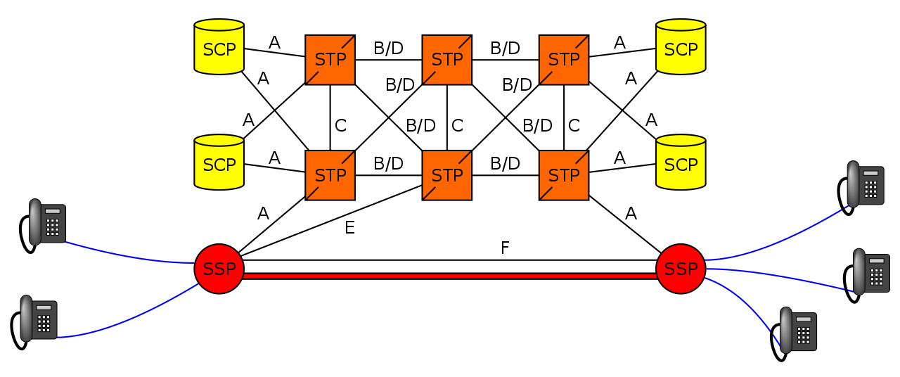
What is in an SS7 Network?
SS7 Networks only have 3 types of network elements:
Service Switching Points (SSP)
Service Transfer Points (STP)
Service Control Points (SCP)
Service Switching Points (SSP)
Service Switching Points (SSPs) are endpoints in the network. They’re the users of the connectivity, they use it to create and send meaningful messages over the SS7 network, and receive and process messages over the SS7 network.
Like a PC or server are IP endpoints on an IP Network, which send and receive messages over the network, an SSP uses the SS7 network to send and receive messages.
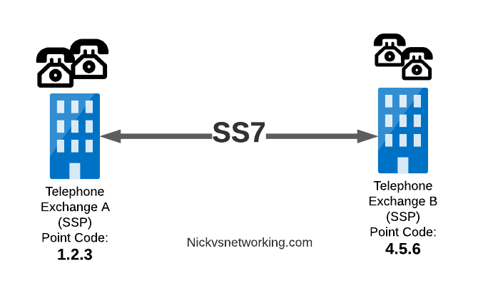
In a PSTN context, your local telephone exchange is most likely an SS7 Service Switching Point (SSP) as it creates traffic on the SS7 network and receives traffic from it.
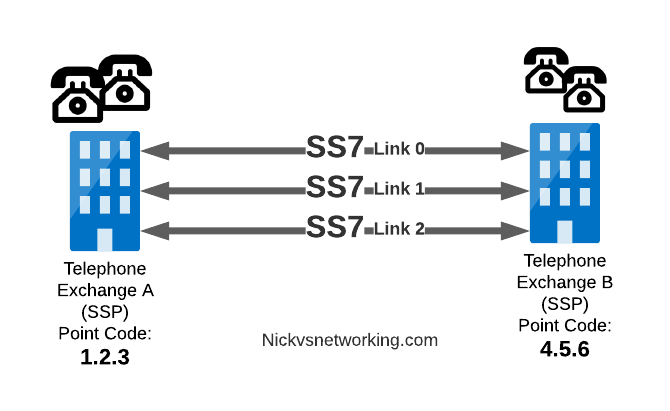
A call from a user on one exchange to a user on another exchange could go from the SSP in Exchange A, to the SSP in Exchange B, in the same way you could send data between two computers by connecting directly between them with an Ethernet crossover cable.
Messages between our two exchanges are addressed using Point Codes, which can be thought of a lot like IP Addresses, except shorter.
In the MTP3 header of each SS7 message is the Destination Point Code, and the Origin Point Code.
When Telephone Exchange A wants to send a message over SS7 to Telephone Exchange B, the MTP header would look like:
MTP3 Header:
Origin Point Code:      1.2.3
Destination Point Code: 4.5.6
Service Transfer Points (STP)
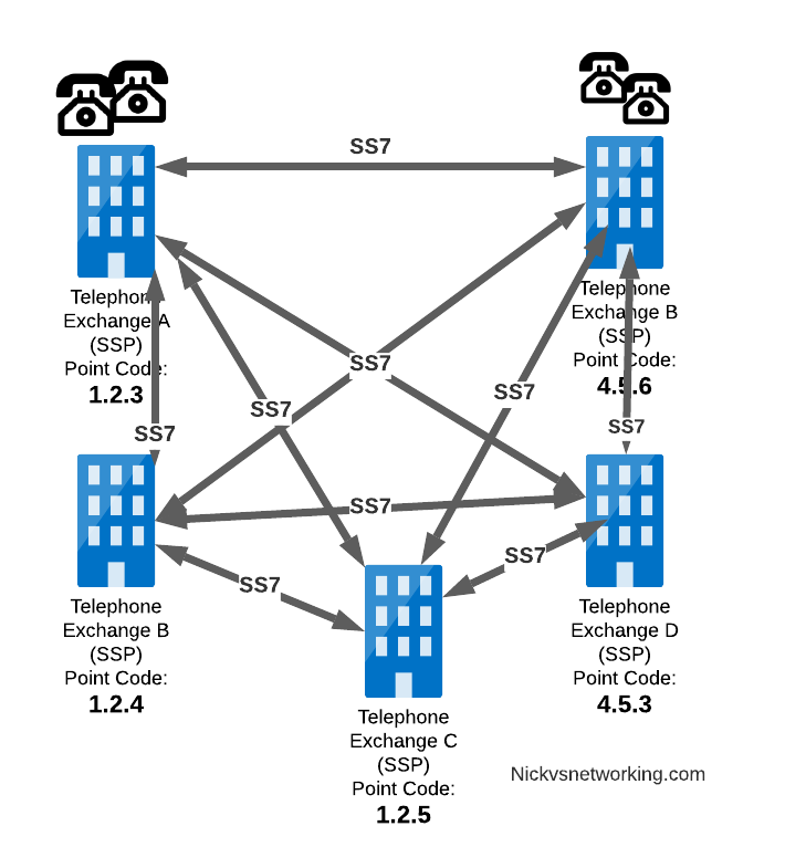
Linking each SSP to each other SSP has a pretty obvious problem as our network grows.
What happens if we’ve got hundreds of SSPs? If we want a full-mesh topology connecting every SSP to every other SSP directly, we’d have a rats nest of links!
A “full-mesh” approach for connecting SSPs does not work at scale, so STPs are introduced
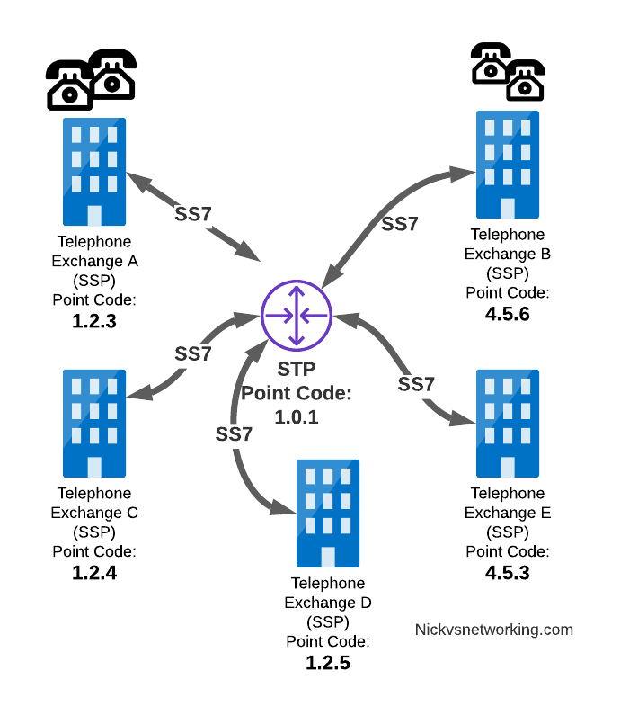
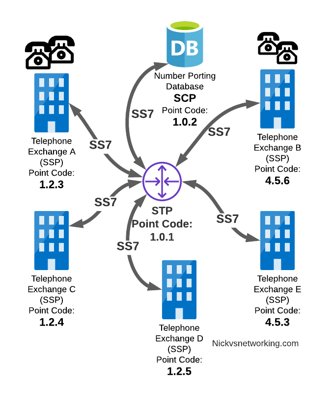
So to keep things clean and scalable, we’ve got Signalling Transfer Points (STPs).
STPs can be thought of like Routers but in an SS7 network.
When our SSP generates an SS7 message, it’s typically handed to an STP which looks at the Destination Point Code, it’s own routing table and routes it off to where it needs to go.
STP acting as a central router to connect lots of SSPs
This means every SSP doesn’t require a connection to every other SSP. Instead by using STPs we can cut down on the complexity of our network.
When Telephone Exchange A wants to send a message over SS7 to Telephone Exchange B, the MTP header would look the same, but the routing table on Telephone Exchange A would be setup to send the requests out the link towards the STP.
MTP3 Header:
Origin Point Code:      1.2.3
Destination Point Code: 4.5.6
Linksets
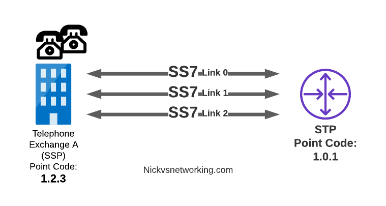
Between SS7 Nodes we have Linksets. Think of Linksets as like LACP or Etherchannel, but for SS7.
You want to have multiple links on every connection, for sharing out the load or for redundancy, and a Linkset is a group of connections from one SS7 node to another, that are logically treated as one link.
Link between an SSP and STP with 3 linksets
Each of the links in a Linkset is identified by a number, and specified in in the MTP3 header’s “Signaling Link Selector” field, so we know what link each message used.
MTP3 Header:
Origin Point Code:       1.2.3
Destination Point Code:  4.5.6
Signaling Link Selector: 2
Service Control Point (SCP)
Somewhere between a Rolodex an relational database, is the Service Control Point (SCP).
For an exchange (SSP) to route a call to another exchange, it has to know the point code of the destination Exchange to send the call to. When fixed line networks were first deployed this was fairly straight forward, each exchange had a list of telephone number prefixes and the point code that served each prefix, simple.
But then services like number porting came along when a number could be moved anywhere. Then 1800/0800 numbers where a number had to be translated back to a standard phone number entered the picture.
To deal with this we need a database, somewhere an SSP can go to query some information in a database and get a response back.
This is where we use the Service Control Point (SCP).
Keep in mind that SS7 long predates APIs to easily lookup data from a service, so there was no RESTful option available in the 1980s.
When a caller on a local exchange calls a toll free (1800 or 0800 number depending on where you are) number, the exchange is setup with the Point Code of an SCP to query with the toll free number, and the SCP responds back with the local number to route the call to.
While SCPs are fading away in favor of technology like DNS/ENUM for Local Number Portability or Routing Databases, but they are still widely used in some networks.
Getting to know the Signalling Transfer Point (STP)
As we saw earlier, instead of a one-to-one connection between each SS7 device to every other SS7 device, Signaling Transfer Points (STP) are used, which act like routers for our SS7 traffic.
The STP has an internal routing table made up of the Point Codes it has connections to and some logic to know how to get to each of them.
Like a router, STPs don’t really create SS7 traffic, or consume traffic, they just receive SS7 messages and route them on towards their destination.
Ok, they do create some traffic for checking links are up, etc, but like a router, their main job is getting traffic where it needs to go.
When an STP receives an SS7 message, the STP looks at the MTP3 header. Specifically the Destination Point Code, and finds if it has a path to that Point Code. If it has a route, it forwards the SS7 message on to the next hop.
Like a router, an STP doesn’t really concern itself with anything higher than the MTP3 layer – As point codes are set in the MTP3 layer that’s the only layer the STP looks at and the upper layers aren’t really “any of its business”.
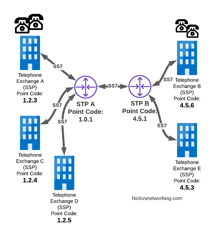
STPs don’t require a direct connection (Linkset) from the Originating Point Code straight to the Destination Point Code. Just like every IP router doesn’t need a direct connection to ever other network. By setting up a routing table of Point Codes and Linksets as the “next-hop”, we can reach Destination Point Codes we don’t have a direct Linkset to by routing between STPs to reach the final Destination Point Code.
Let’s work through an example:
And let’s look at the routing table setup on STP-A:
STP A Routing Table:
1.2.3 - Directly attached (Telephone Exchange A)
1.2.4 - Directly attached (Telephone Exchange C)
1.2.5 - Directly attached (Telephone Exchange D)
4.5.1 - Directly attached (STP-B)
4.5.3 - Via STP-B
4.5.6 - Via STP-B
So what happens when Telephone Exchange A (Point Code 1.2.3) wants to send a message to Telephone Exchange E (Point Code 4.5.3)? Firstly Telephone Exchange A puts it’s message on an MTP3 payload, and the MTP3 header will look something like this:
MTP3 Header:
Origin Point Code:       1.2.3
Destination Point Code:  4.5.3
Signaling Link Selector: 1
Telephone Exchange A sends the SS7 message to STP A, which looks at the MTP3 header’s Destination Point Code (4.5.3), and then in it’s routing table for a route to the destination point. We can see from our example routing table that STP A has a route to Destination Point Code 4.5.3 via STP-B, so sends it onto STP-B.
For STP-B it has a direct connection (linkset) to Telephone Exchange E (Point Code 4.5.3), so sends it straight on
Like IP, Point Codes have their own form of Variable-Length-Subnet-Routing which means each STP doesn’t need full routing info for every Destination Point Code, but instead can have routes based on part of the point code and a subnet mask.
But unlike IP, there is no BGP or OSPF on SS7 networks. Instead, all routes have to be manually specified.
For STP A to know it can get messages to destinations starting with 4.5.x via STP B, it needs to have this information manually added to it’s route table, and the same for the return routing.
Sigtran & SS7 Over IP
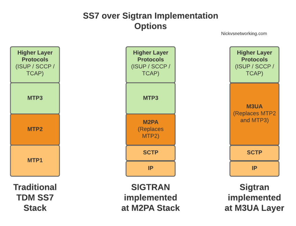
As the world moved towards IP enabled everything, TDM based Sigtran Networks became increasingly expensive to maintain and operate, so a IETF taskforce called SIGTRAN (Signaling Transport) was created to look at ways to move SS7 traffic to IP.
When moving SS7 onto IP, the first layer of SS7 (MTP1) was dropped, as it primarily concerned the physical side of the network. MTP2 didn’t really fit onto an IP model, so a two options were introduced for transport of the MTP2 data, M2PA (Message Transfer Part 2 User Peer-to-Peer Adaptation Layer) and M2UA (MTP2 User Adaptation Layer) were introduced, which rides on top of SCTP. This means if you wanted an MTP2 layer over IP, you could use M2UA or M2TP.
SCTP is neither TCP or UDP. I’ve touched upon SCTP on this blog before, it’s as if you took the best bits of TCP without the issues like head of line blocking and added multi-homing of connections.
So if you thought all the layers above MTP2 are just transferred, unchanged on top of our M2PA layer, that’s one way of doing it, however it’s not the only way of doing it.
There are quite a few ways to map SS7 onto IP Networks, which we’ll start to look into it more detail, but to keep it simple, for the next few posts we’ll be assuming that everything above MTP2/M2PA remain unchanged.
In the next post, we’ll get some actual SS7 traffic flowing!
This is part of a series of posts looking into SS7 and Sigtran networks. We cover some basic theory and then get into the weeds with GNS3 based labs where we will build real SS7/Sigtran based networks and use them to carry traffic.
If you use a mobile phone, a VoIP system or a copper POTS line, there’s a high chance that somewhere in the background, SS7 based signaling is being used.
The signaling for GSM, UMTS and WCDMA mobile networks all rely on SS7 based signaling, and even today the backbone of most PSTN traffic relies SS7 networks. To many this is mysterious carrier tech, and as such doesn’t get much attention, but throughout this series of posts we’ll take a hands-on approach to putting together an SS7 network using GNS3 based labs and connect devices through SS7 and make some stuff happen.
Overview of SS7
Signaling System No. 7 (SS7/C7) is the name for a family of protocols originally designed for signaling between telephone switches. In plain English, this means it was used to setup and teardown large volumes of calls, between exchanges or carriers.
When carrier A and Carrier B want to send calls between each other, there’s a good chance they’re doing it over an SS7 Network.
But wait! SIP exists and is very popular, why doesn’t everyone just use SIP? Good question, imaginary asker. The answer is that when SS7 came along, SIP was still almost 25 years away from being defined. Yes. It’s pretty old.
SS7 isn’t one protocol, but a family of protocols that all work together – A “protocol stack”. The SS7 specs define the lower layers and a choice of upper layer / application protocols that can be carried by them.
The layered architecture means that the application layer at the top can be changed, while the underlying layers are essentially the same.
This means while SS7’s original use was for setting up and tearing down phone calls, this is only one application for SS7 based networks. Today SS7 is used heavily in 2G/3G mobile networks for connectivity between core network elements in the circuit-switched domain, for international roaming between carriers and services like Local Number Portability and Toll Free numbers.
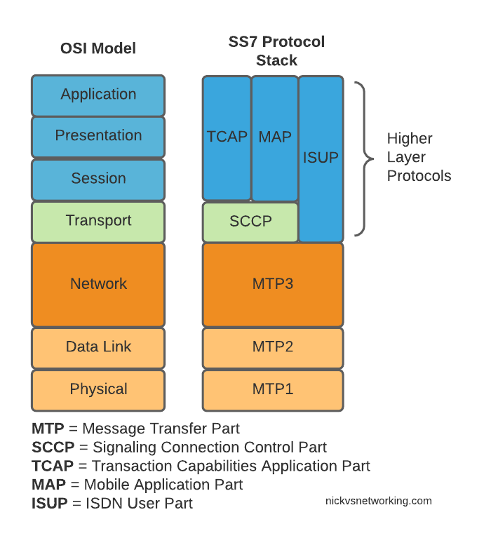
Here’s the layers of SS7 loosely mapped onto the OSI model (SS7 predates the OSI model as well):
OSI Model (Left) and SS7 Protocol Stack (Right)
We do have a few layers to play with here, and we’ll get into them all in depth as we go along, but a brief introduction to the underlying layers:
MTP 1 – Message Transfer Part 1
This is our physical layer. In this past this was commonly E1/T1 lines.
It’s responsible for getting our 1s and 0s from one place to another.
MTP 2 – Message Transfer Part 2
MTP2 is responsible for the data link layer, handling reliable transfer of data, in sequence.
MTP 3 – Message Transfer Part 3
The MTP3 header contains an Originating and a Destination Point Code.
These point codes can be thought of as like an IP Address; they’re used to address the source and destination of a message. A “Point Code” is the unique address of a SS7 Network element.
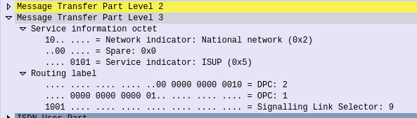
MTP3 header showing the Destination Point Code (DPC) and Origin Point Code (OPC) on a National Network, carrying ISUP traffic
Every message sent over an SS7 network will contain an Origin Point Code that identifies the sender, and a Destination Point Code that identifies the intended recipient.
This is where we’ll bash around at the start of this course, setting up Linksets to allow different devices talking to each other and addressing each other via Point Codes.
The MTP3 header also has a Service Indicator flag that indicates what the upper layer protocol it is carrying is, like the Protocol indicator in IPv4/IPv6 headers.
A Signaling Link Selector indicates which link it was transported over (did I mention we can join multiple links together?), and a Network Indicator for determining if this is signaling is at the National or International level.
TUP/MAP/SCCP/ISUP
These are the “higher-layer” protocols. Like FTP sits on top of TCP/IP, a SS7 network can transport these protocols from their source to their destination, as identified by the Origin Point Code (OPC), to the Destination Point Code (DPC), as specified in the MTP3 header.
We’ll touch on these protocols more as we go on. SCCP has it’s own addressing on top of the OPC/DPC (Like IP has IP Addressing, but TCP has port numbers on top to further differentiate).
Why learn SS7 today?
SS7 and SIGTRAN are still widely in use in the telco world, some of it directly, other parts derived / evolved from it.
So stick around, things are about to get interesting!
We’ve covered SMS in the past, but MMS is a different kettle of fish.
Let’s look at how the call flow goes, when Bob wants to send a picture to Alice.
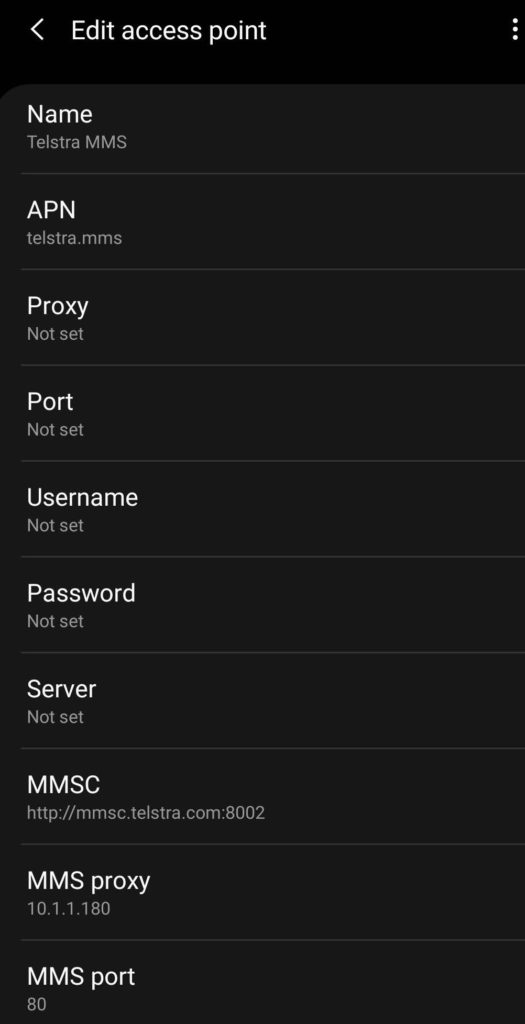
Before Bob sends the MMS, his phone will have to be setup with the correct settings to send MMS. Sometimes this is done manually, for others it’s done through the Carrier provisioning SMS that preloads the settings, and for others it’s baked in based on the Android Carrier settings XML,
APN settings for Telstra in Australia for MMS
It’s made up of the APN to send MMS traffic over, the MMSC address (Multimedia Message Switching Center) and often an MMS proxy and port combination for where the traffic will actually go.
Message Flow – Bob to MMSC (Mobile Originated MMS)
Bob opens his phone, creates a new message to Alice, selects the picture (or other multimedia filetype) to send to her and hits the send button.
For starters, MMS has a file size limit, like MTU it’s not advertised, so you don’t know if you’ve hit it, so rather like MTU is a “lowest has the highest success of getting through” rule. So Bob’s phone will most likely scale the image down to fit inside 300K.
Next Bob’s phone knows it has an MMS to send, for this is opens up a new bearer on the MMS APN, typically called MMS, but configured in the phone by Bob.
Why use a separate APN for sending 300K of MMS traffic? Once upon a time mobile data was expensive. By having a separate APN just for MMS traffic (An APN that could do nothing except send / receive MMS) allowed easier billing / tariffing of data, as MMS traffic was sent over a APN which was unmetered.
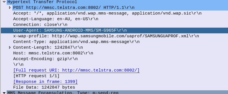
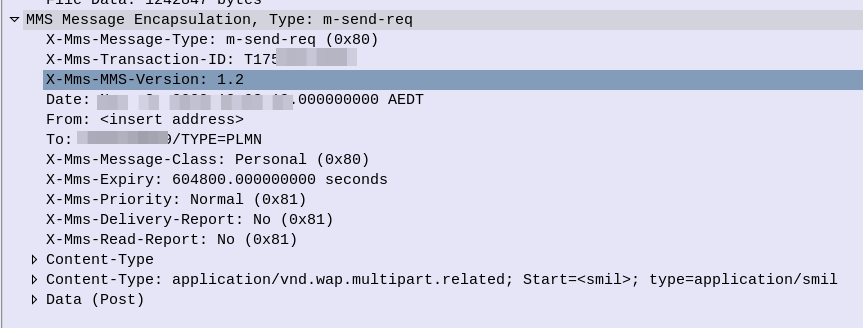
After the bearer is setup on the MMS APN, Bob’s phone begins crafting a HTTP 1.1 Post to be sent to the MMSC. The content type of this request will be application/vnd.wap.mms-message and the body of the HTTP post will be made up of MMS Message Encapsulation, with the body containing the picture he wants to send to Alice.
Note: Historically Wireless Session Protocol (WSP) was used in lieu of HTTP. These clients would now need a WAP gateway to translate into HTTP.
This HTTP Post is then sent to the MMSC Address, or, if present, the MMSC Proxy address. This traffic is sent over the MMS APN that we just brought up.
HTTP POST Headers for the MO MMS MessageMMS Message Encapsulation from MO MMS Message
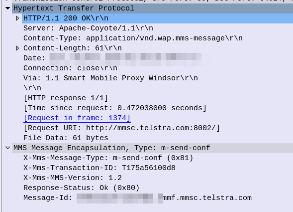
The MMSC receives this information, and then, if all was successful, responds with a 200 OK,
200 OK response to MO MMS Message
So now the MMSC has the information from Bob, let’s flip over to Alice.
Message Flow – MMSC to Alice (Mobile Terminated MMS)
For the purposes of simplicity, we’re going to rule out the MMSC from doing clever things like converting the media, accepting email (SMPP) as MMS, etc, etc. Instead we’re going to assume Alice and Bob are on the same Network, and our MMSC is just doing store-and-forward.
The MMSC will look at the To address in the MMS Message Encapsulation of the request Bob sent, to determine that this message is destined for Alice.
The MMSC will load the media content (photo) sent by Bob destined for Alice and serve it via HTTP. The MMSC generates a random URL to serve it this particular file on, with each MMS the MMSC handles being assigned a random URL containing the media content.
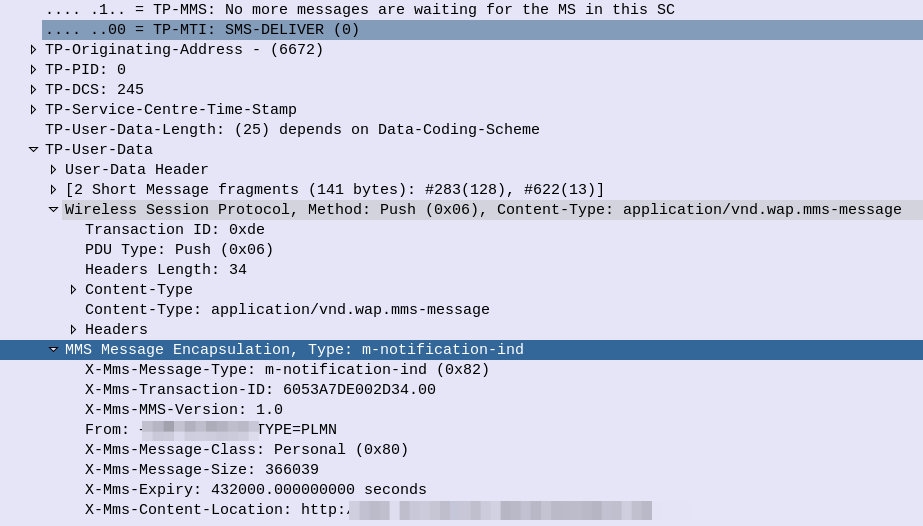
Next the MMSC will need to tell Alice’s phone, that she has an MMS waiting for her. This is done by generating an SMS to send to Alice’s phone,
The user-data of this SMS is the Wireless Session Protocol with the method PUSH – Aka WAP Push.
SMS alerting the user of an MMS waiting for delivery
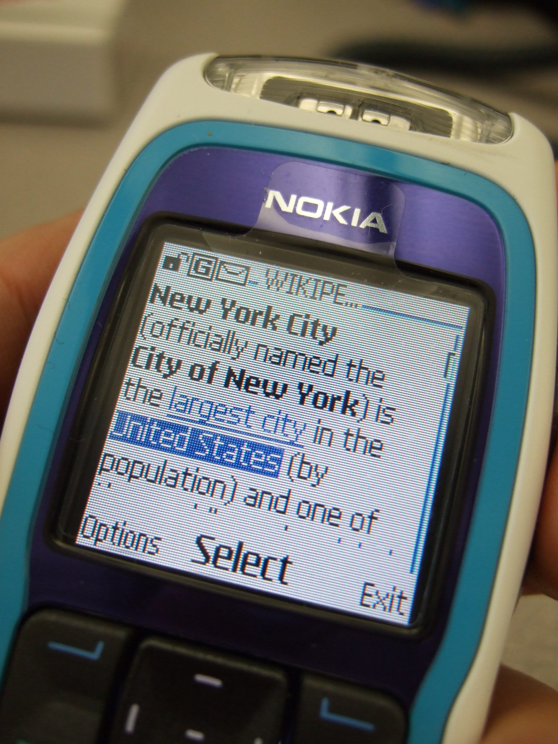
This specially encoded SMS is parsed by the Alice’s phone, which tells the her there is an MMS message waiting for her.
On some operating systems this is pulled automatically, on others, users need to select “Download” to actually get the file.
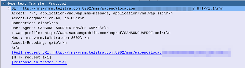
The UE then just runs an HTTP get to the address in the X-Mms-Content-Location: Header to pull the multimedia content that Bob sent.
HTTP GET from Alice’s Phone / UE to retrieve MMS sent by Bob (MT-MMS)
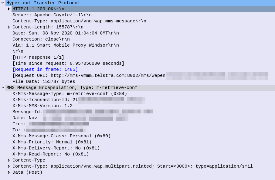
All going well the URL is valid and Alice’s phone retrieves the message, getting a 200 OK back from the server with the message content.
HTTP Response (200 OK) for MT-MMS, sent by the MMSC to Alice’s phone with the MMS Body
So now Alice’s phone has the MMS content and renders it on the screen, Alice can see the Photo Bob sent her.
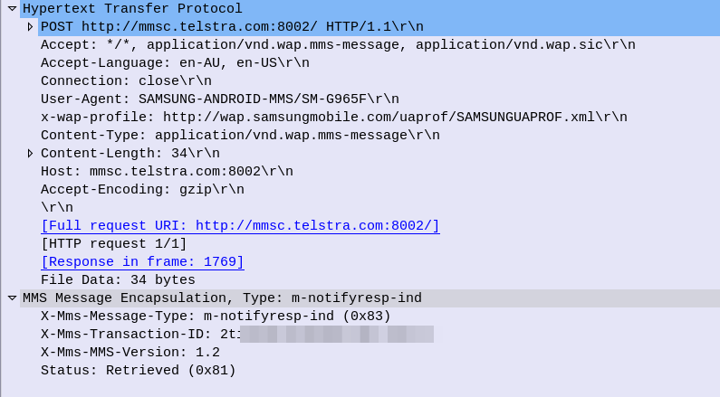
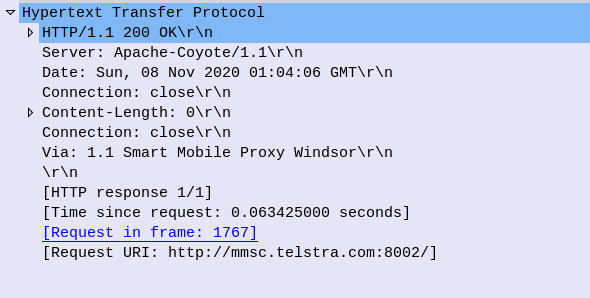
Lastly Alice’s phone sends a HTTP POST again to the MMSC, this time indicating the message status is “Retrieved”,
And to close everything off the MMSC confirms receipt of the Retrieved status with a 200 OK, and we are done.
What didn’t we cover?
So that’s a basic MMS message flow, but there’s a few parts we didn’t cover.
The overall architecture beyond just the store-and forward behaviour, charging and authentication we didn’t cover. So let’s look at each of these points.
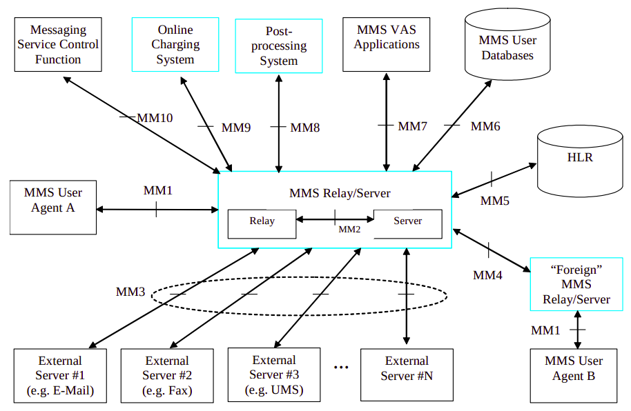
Overall Architecture
What we just covered what what’s defined as the MM1 interface.
There’s obviously a stack of other interfaces, such as for charging, messaging between MMSC/Carriers, subscriber locating / user database, etc.
Charging
MMSCs would typically have a connection to trigger charging events / credit-control events prior to processing the message.
For online charging the Ro interface can be used, as you would for IMS charging events.
3GPP 3GPP TS 32.270 covers the charging architecture for online/offline charging for MMS.
Authentication
Unfortunately authentication was a bit of an afterthought for the MMS standard, and can be done several different ways.
The most common is to correlate the IP Address on the MMS APN against a subscriber.
Network Slicing, is a new 5G Technology. Or is it?
Pre 3GPP Release 16 the capability to “Slice” a network already existed, in fact the functionality was introduced way back at the advent of GPRS, so what is so new about 5G’s Network Slicing?
Network Slice: A logical network that provides specific network capabilities and network characteristics
3GPP TS 123 501 / 3 Definitions and Abbreviations
Let’s look at the old and the new ways, of slicing up networks, pre release 16, on LTE, UMTS and GSM.
Old Ways: APN Separation
The APN or “Access Point Name” is used so the SGSN / MME knows which gateway to that subscriber’s traffic should be terminated on when setting up the session.
APN separation is used heavily by MVNOs where the MVNO operates their own P-GW / GGSN. This allows the MNVO can handle their own rating / billing / subscriber management when it comes to data. A network operator just needs to setup their SGSN / MME to point all requests to setup a bearer on the MVNO’s APN to the MNVO’s gateways, and presoto, it’s no longer their problem.
Later as customers wanted MPLS solutions extended over mobile (Typically LTE), MNOs were able to offer “private APNs”. An enterprise could be allocated an APN by the MNO that would ensure traffic on that APN would be routed into the enterprise’s MPLS VRF. The MNO handles the P-GW / GGSN side of things, adding the APN configuration onto it and ensuring the traffic on that APN is routed into the enterprise’s VRF.
Different QCI values can be assigned to each APN, to allow some to have higher priority than others, but by slicing at an APN level you lock all traffic to those QoS characteristics (Typically mobile devices only support one primary APN used for routing all traffic), and don’t have the flexibility to steer which networks which traffic from a subscriber goes to.
It’s not really practical for everyone to have their own APNs, due in part to the namespace limitations, the architecture of how this is usually done limits this, and the simple fact of everyone having to populate an APN unique to them would be a real headache.
5G replaces APNs with “DNNs” – Data Network Names, but the functionality is otherwise the same.
In Summary: APN separation slices all traffic from a subscriber using a special APN and provide a bearer with QoS/QCI values set for that APN, but does not allow granular slicing of individual traffic flows, it’s an all-or-nothing approach and all traffic in the APN is treated equally.
The old Ways: Dedicated Bearers
Dedicated bearers allow traffic matching a set rule to be provided a lower QCI value than the default bearer. This allows certain traffic to/from a UE to use GBR or Non-GBR bearers for traffic matching the rule.
The rule itself is known as a “TFT” (Traffic Flow Template) and is made up of a 5 value Tuple consisting of IP Source, IP Destination, Source Port, Destination Port & Protocol Number. Both the UE and core network need to be aware of these TFTs, so the traffic matching the TFT can get the QCI allocated to it.
This can be done a variety of different ways, in LTE this ranges from rules defined in a PCRF or an external interface like those of an IMS network using the Rx interface to request a dedicated bearers matching the specified TFTs via the PCRF.
Unlike with 5G network slicing, dedicated bearers still traverse the same network elements, the same MME, S-GW & P-GW is used for this traffic. This means you can’t “locally break out” certain traffic.
In Summary: Dedicated bearers allow you to treat certain traffic to/from subscribers with different precedence & priority, but the traffic still takes the same path to it’s ultimate destination.
This means one eNodeB can broadcast more than one PLMN and server more than one mobile network.
This slicing is very coarse – it allows two operators to share the same eNodeBs, but going beyond a handful of PLMNs on one eNB isn’t practical, and the PLMN space is quite limited (1000 PLMNs per country code max).
In Summary: MOCN allows slicing of the RAN on a very coarse level, to slice traffic from different operators/PLMNs sharing the same RAN.
Its use is focused on sharing RAN rather than slicing traffic for users.
In our last Osmocom post we talked about the basics of packet data, and configuring our BTSs to support it.
In this post we’ll take a look at using Osmocom’s Serving Gateway Support Node (SGSN) named OsmoSGSN.
At the BSC traffic is divided into two categories, Circuit Switched (CS) traffic (Like voice calls & SMS) which is handed by the MSC, and Packet Switched (PS) traffic (Mobile data) is handled by the SGSN.
The SGSN acts as an anchor point for our packet data, it connects our BSC (that handles our RAN) to the GGSN (that handles the connection to external data networks).
Although it’s not technically possible to run a data only 2G/3G network (you require the MSC) it almost could be. The SGSN handles authentication of subscribers, and runs the PS network completely standalone from the CS network. The SGSN does it’s own handover management, authentication, etc, without any connection to the MSC.
Basic SGSN Config
Like the previous Osmocom network elements we’ve covered, we’ll access the SGSN via Telnet on localhost (the server running the Osmocom stack) on port 4254.
Once we’ve accessed the terminal we’ll escalate our privileges using the enable command, and run configure terminal to start configuring,
We’ll begin by setting the local IP our SGSN will listen on, the gtp local-ip, we’ll need this to be externally accessible for our BTSs, so set it to the IP of the server.
sgsn
  gtp local-ip 10.0.1.201
Next we’ll need to configure the IP of our GGSN. It gets a bit messy if we’re running everything on one box, as we’re going to have the SGSN and the GGSN trying to communicate on the same ports for GTP, so best to assign an IP in the loopback range, like 127.0.0.2 in my case, for the GGSN:
We can also steer GGSN selection based on the APN, for example an APN for a corporate network, you may want to have a dedicated GGSN for, for example, we could create a second GGSN – GGSN 1 and route any traffic on our “special.access.net” APN to that GGSN, and everything else to GGSN0:
You may notice that APNs look like domain names – that’s because they can be,
If we owned the domain special.access.net we could set it to resolve to the GGSN IP we’re using for the special.access.net GGSN at 10.0.1.99, and instead of hardcoding the IP in our config use a DNS server (like 8.8.8.8) to resolve these.
To learn more about setting up compression and encryption of the data, take a look in the Osmo-SGSN Manual.
Charging
Charging in mobile networks is a topic we could spend weeks on, but we’re not going to!
OsmoSGSN implements a simple CDR based charging mechanism that writes to a text file a simple CSV file with most importantly the IMSI and bytes in / out for each subscriber, that can be used to implement offline charging (Post paid) if required, and with some hacky scripts can even cut off sessions after reaching a certain amount of throughput (online charging aka pre-paid).
By adding the below to our config OsmoSGSN will write CDRs into /home/nick/sgsn.cdr every 60 seconds.
These antennas claimed to operate on 900/1800/2100MHz and this time had the correct connector (SMA not RP-SMA)…
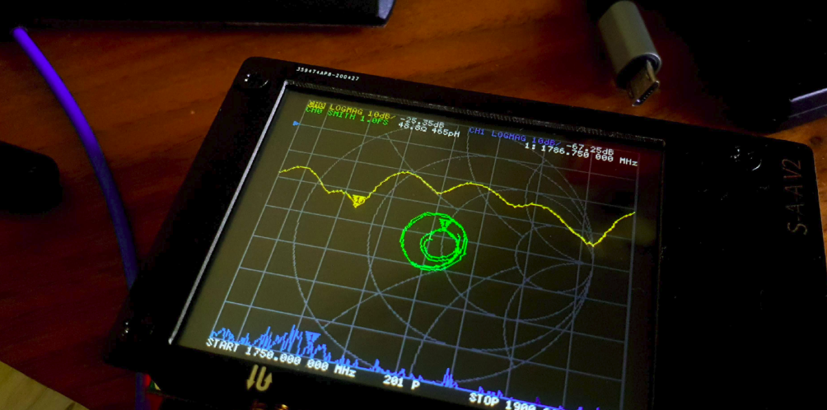
I ordered two of these antennas for the princely sum of $3 and hooked them onto the NanoVNA to analyse the antennas – the poor man’s Anritsu SiteMaster!
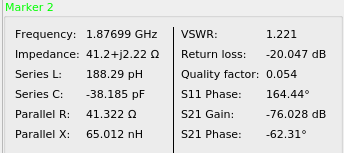
I was operating the GSM network using ARFCN 871 with the SDR which translates to 1782 MHz for Uplink and 1877 MHz for Downlink, so I plugged in the values into the VNA to take a look at how it performs in those ranges,
Performance is actually pretty on point,
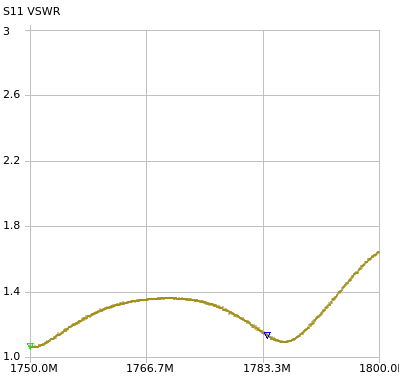
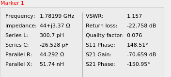
On the Uplink frequency we’ve got a VSWR of 1.15 which is about as good as it gets,
And in the downlink we’ve got a VSWR of 1.221, still pretty good.
Performance on the remainder of the 1800MHz band is pretty decent, with clear drops in VSWR where the Uplink and Downlink channels lie.
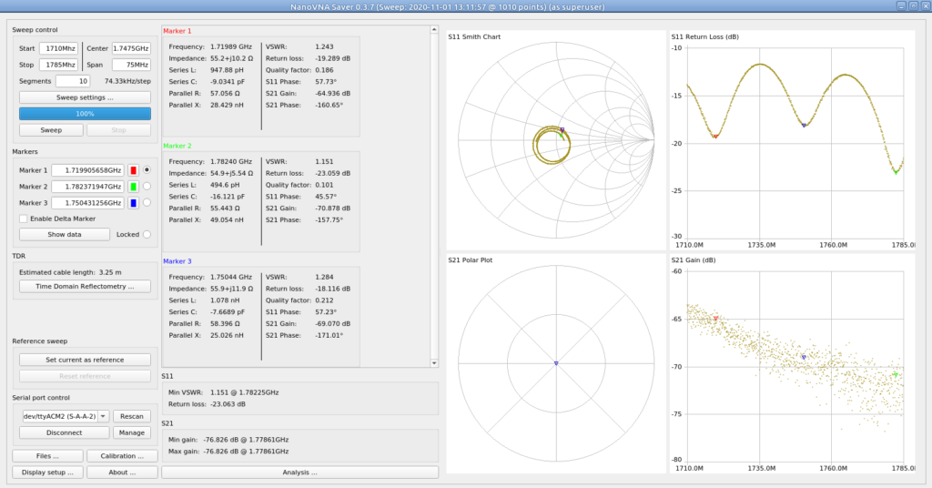
I measured the full band for Uplink on the 1800Mhz band (1710Mhz – 1785Mhz):
Analysis of Uplink Bands
Which shows not all channels are created equal, if you were looking for real performance on these antennas and not just playing, you’d probably want to put your uplink channel on one of the frequencies shown by the marker,
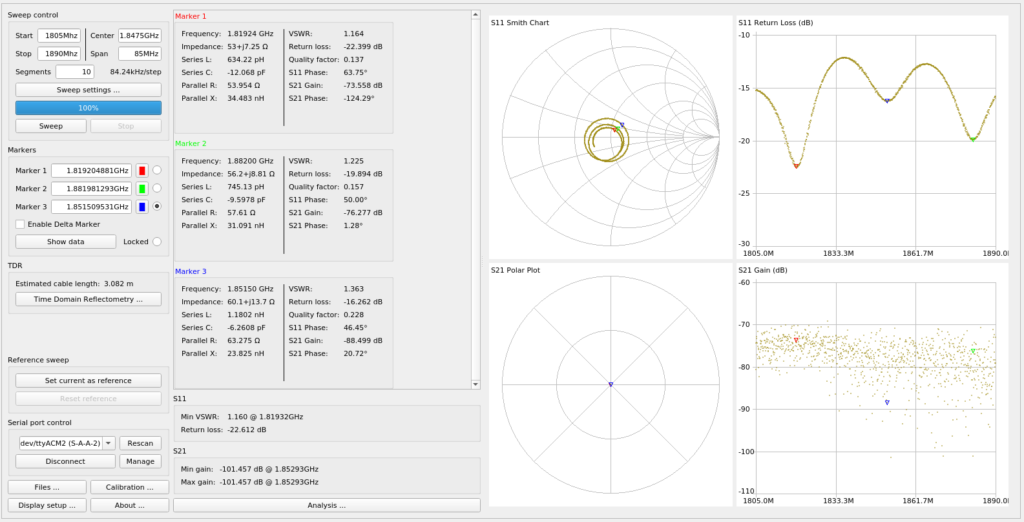
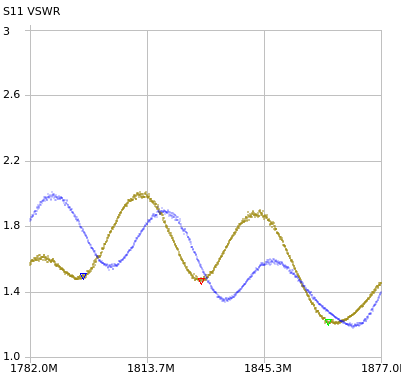
And the full band for Downlink on the 1800Mhz band (1805Mhz – 1890Mhz):
Again, varied performance, but the peaks and troughs line up on the uplink and downlink, so a lower ARFCN in the 1800Mhz band would put you about on the red marker for both,
Comparing the output of each of the antennas I’ve got
In reality I could be using a bent coat hanger for an antenna, the signals shouldn’t be able to leave the room, but it’s a good excuse to use the toys!
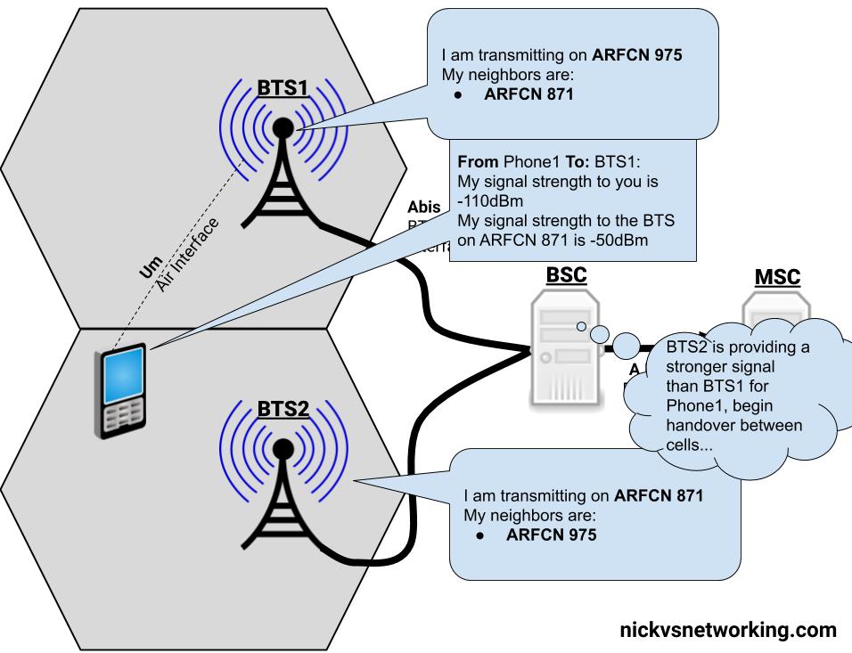
With just one cell/BTS, your mobile phone isn’t all that mobile.
So GSM has the concept of handovers – Once BTS (cell) can handover a call to another cell (BTS), thus allowing us to move between BTSs and keep talking on a call.
Note: I’ll use the term BTS here, because we’ve talked a lot about BTSs throughout this series. Technically a BTS can be made up of one or more cells, but to keep the language consistent with the rest of the posts I’ll use BTS, even though were talking about the cell of a BTS.
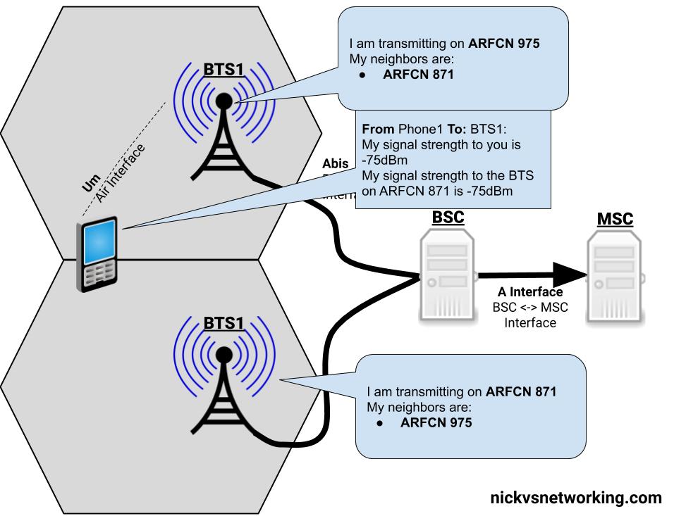
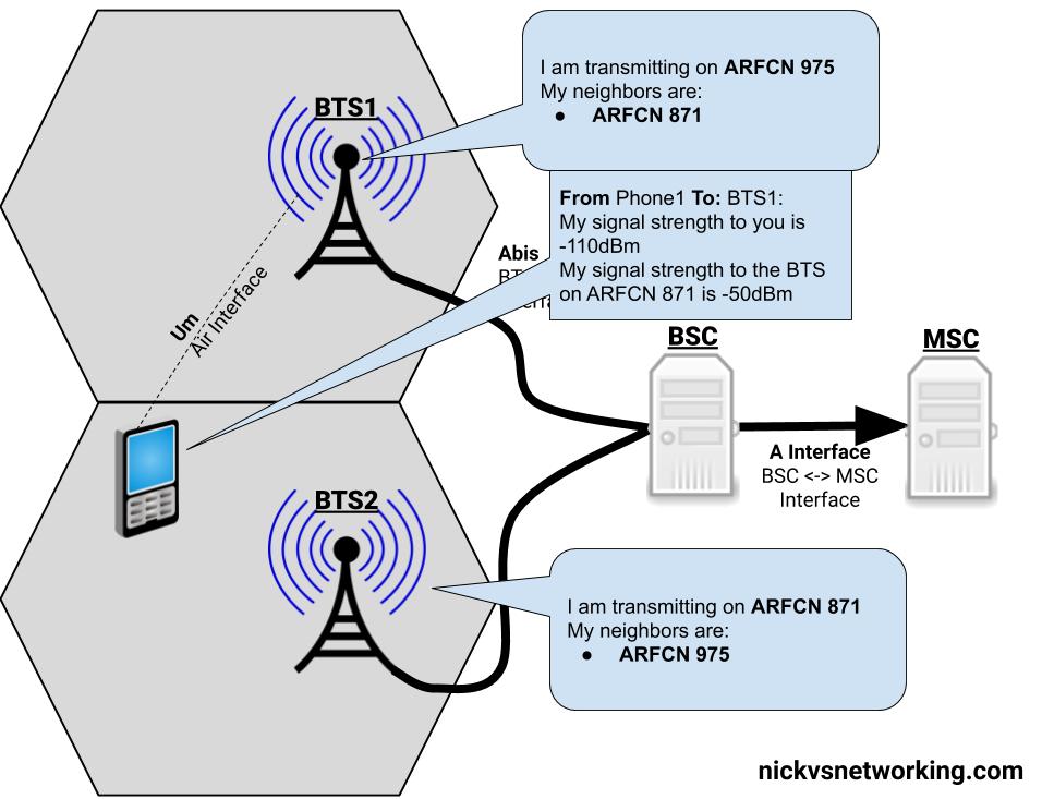
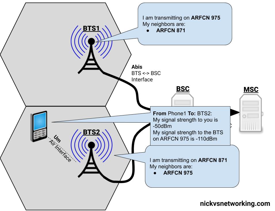
If we’re on a call, in an area served by BTS1, and we’re moving towards BTS2, at some point the signal strength from BTS2 will surpass the signal strength from BTS1, and the phone will be handed over from BTS1 to BTS2.
Handovers typically only occur when a channel is in use (ie on a phone call) if a phone isn’t in use, there’s no need to seamlessly handover as a brief loss of connectivity isn’t going to be noticed by the users.
Measurements
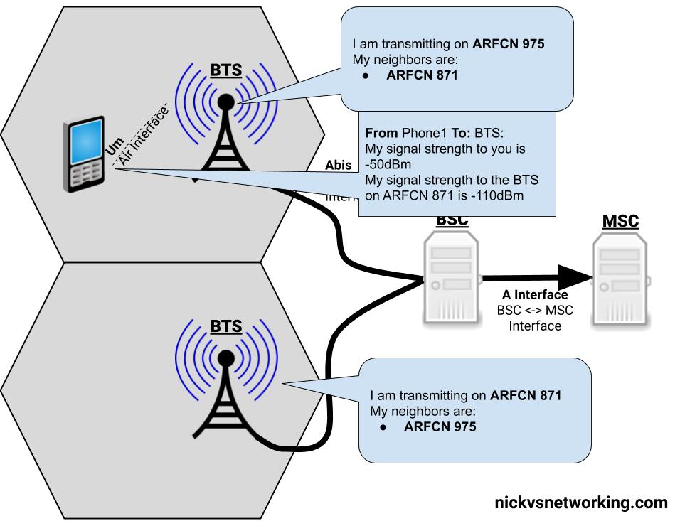
The question as to when to handover a call to a neighbouring cell, comes down to the signal strength levels the phone is experiencing.
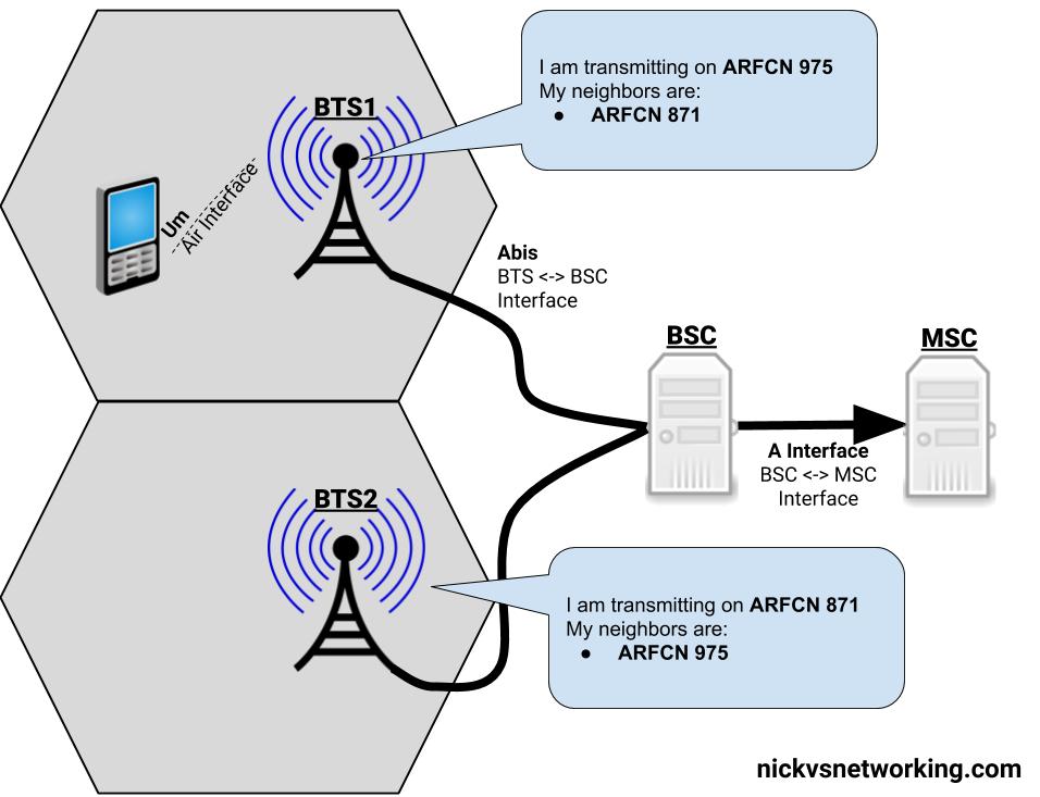
The phone measures the signal strength of up to 6 nearby (neighbouring) BTSs, and reports what signal strength it’s receiving to the BTS that’s currently serving it.
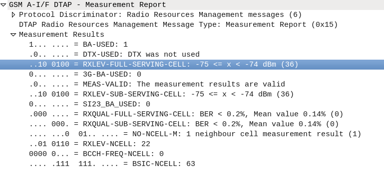
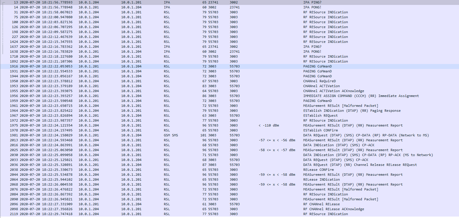
The BTS then sends this info to the BSC, in the RXLEV fields of a RSL Measurement Report packet.
RXLEV fields of a RSL Measurement Report packet.
With this information the BSC makes the determination of when to handover the call to a neighbouring BTS.
There’s a lot of parameters that the BSC takes into account when making the decision to handover to a neighbouring BTS, but for the purposes of this explanation, we’ll simplify this and just imagine it’s based on which BTS has the strongest signal strength as seen by the phone.
Everybody needs good Neighbors
Our phone can only monitor the signal strength of so many neighboring cells at once (Up to 6). So in order to know which frequency (known as ARFCNs) to take signal strength measurements on, our phone needs to know the frequencies it should expect to see neighbours, so it can measure these frequencies.
The System Information Block 2 is broadcast by the BTS on the BCCH and SACCH channels, and contains the ARFCNs (Frequencies) of the BTSs that neighbour that cell.
With this info our Phone only needs to monitor the frequencies (ARFCNs) of the cells nearby it’s been told about in the SIB2 to check the received power levels on those frequences.
The Handover
This is vastly simplified…
So our phone is armed with the list of neighbouring cell frequencies (ARFCNs) and it’s taking signal strength measurements and sending them to the BTS, and onto the BSC. The BSC knows the strength of the signals around our phone on a call.
With this information the BSC makes the decision that the serving cell (BTS) the phone is currently connected to is no longer the best candidate, as another BTS would provide a higher signal strength and begins a handover to a neighbouring BTS with a better signal to the phone.
Our BSC starts by giving the new BTS a heads up it’s going to hand a call of to it, by setting up the channel to use on the new BTS, through a Channel Activation message.
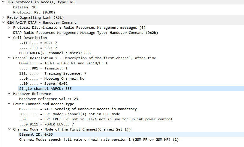
Next a handover command is sent to the phone via the BTS it was initially connected to (RSL Handover Command), telling the phone to begin handover to the new BTS and the channel it should move to on the new BTS it setup earier.
Screenshot of a packet capture showing a GSM Handover
The phone moves to the new BTS, and is acknowledged by the phone. The channels the phone was using on the old BTS are released and the handover is complete.
Simplified Diagram of the Process
There is a lot more to handovers than just this, which we’ll cover in a future post.
When setting up the timeslots on the TRX for each BTS on your BSC, you’ll notice you have to set a channel type.
So what do these acronyms mean, and how do they affect the performance of the network?
GSM channels break down into one of to categories, control channels – used for signalling, and traffic channels, used for carrying information to/from a user.
A network with only control channels wouldn’t allow a call to be made, as there would be no traffic channels to carry the audio of the call,
Conversely a network with only traffic channels would have plenty of capacity for calls, but without a control channel would have no way of setting them up.
Traffic Channels
Traffic channels break down into a further two categories, voice channels for carrying call audio, and data channels for carrying GPRS data.
Traffic Channels for Voice
There’s a few variants of voice channel based on the codec used for encoding the voice data, the more compressed / small the audio signal is, the more you can cram in per channel, at the sacrifice of voice quality.
Common options are Traffic Channel – Full Rate (TCH/F), & Traffic Channel – Half Rate (TCH/F) channels.
Traffic Channels for Data
When GPRS was introduced it needed to be transported on a traffic channel, but unlike a voice channel, the resources weren’t going to be used 100% of the time (like in a voice call) and could be shared on an as-needed basis.
Data channels are also also broken down into full rate and half rate channels, like Traffic Channel – Full Rate (TCH/F), & Traffic Channel – Half Rate (TCH/F) channels.
Control Channels
Control channels carry the out of band signalling between the Phone and the BTS.
Broadcast Channels
Broadcast Channels are by their very nature – Broadcasted, this means every phone on the BTS gets these messages.
There are 3 broadcast channels, the FCCH for frequency corrections, SCH for synchronisation and BCCH for a common channel that transmits information to all phones, containing info on the network such as the PLMN, neighbouring cells, etc.
Common Channels
The PCH – Paging Channel, is used to page phones in idle mode. All phones will listen on the paging channel, and if they hear their identifier will establish a connection back to the network.
RACH the Random Access Control Channel is used for when the phone wants to establish a connection with the network, by picking a random timeslot to transmit it’s data on the RACH.
The ACGC is the Access Grant Channel, containing information about dedicated channels to be assigned to phones.
Dedicated Control Channels
Like dedicated traffic channels, dedicated channels are only in use by one phone at a time.
The SDCCH is the standalone dedicated control channel, over which location updates, SMS, authentication & call setup / teardown signalling is transferred.
The SACCH – slow Associated Control Channel is used for timing advance (when users are further from the BTS timing advances are needed to ensure propogation time is taken into account), power control information, signaling data and radio measurements.
Finally the FACCH – Fast Associated Control is used for transferring larger messages such as for handover information,
Depending on if you’re wearing a tin foil hat or not, silent SMS and silent calls could be a useful tool to for administering the network or a backdoor put in to track citizenry!
Regardless of it’s reasons for existence, let’s take a look at what it actually does, and how we can use it.
To conserve battery and radio resources, terminals / UEs go into an idle state where they monitor the RSSI of the BTS/NodeB and the broadcast/paging channels, but don’t actively send anything on the uplink.
Let’s say we wanted to get the RSSI measurements from a terminal/UE we would need the terminal to go into an active state.
We could do this by calling the terminal, or sending an SMS, but if we wanted to do it without alerting the user, that’s when we can use Silent SMS and silent calls, to do so without alerting the user.
If you want to try this you can send a Silent SMS from Osmo-MSC.
Packet capture shows no traffic on the Abis interface until the Silent SMS is sent
On top of Silent SMS there’s also silent calls, allowing for a continued stream of measurements from the UE, which can also be super useful for creating a single call leg.
Another use for Silent SMS it to interface with the SIM Card, many card manufacturers provide support for “over the air” updating of the SIM Card parameters (think if MNO A purchases MNO B and they want to share a network, you don’t want to have to re-issue every SIM card with the updated PLMN, just update the parameters on the SIM).
Messages from the network operator to their SIM cards don’t need to be shown to the user, so are can be carried via Silent SMS. – SIM card manufacturers don’t make the nitty gritty details of this functionality public – it’s a proprietary interface defined by the manufacturer, simply transported by SMS.
So far we’ve focused on building a plain “2G” (voice and SMS only) network, which was all consumers expected twenty years ago.
As the number of users accessing the internet through DSL, Dial Up & ISDN grew, the idea of getting this data “on the go” became more appealing. TCP/IP was becoming the dominant standard for networking, the first 802.11 WiFi spec had recently been published and demand for mobile data was growing.
There’s a catch however – TCP/IP was never designed to be mobile.
An IP address exists in a single location.
(Disclaimer: While you can “move” a subnet by advertising itself out in a different location via BGP peering relationships with other operators, it’s cumbersome, can only be done per /24 or larger, and most importantly it’s painfully slow. IPv6 has MIPv6 which attempts to fix some of these points, but that’s outside of this scope.)
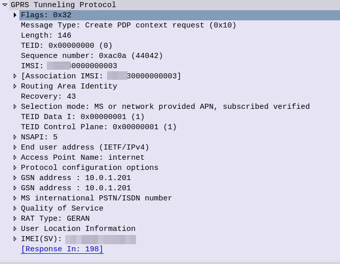
GPRS addressed the mobility issue by having a single fixed point the IP Address is assigned to (the Gateway GPRS Support Node), which encapsulates IP traffic to/from a mobile user into GTP Packet (GPRS Tunnelling Protocol), like GRE or any of the other common routing encapsulation protocols, allowing the traffic to be rerouted to different destinations as the users move from being served by one BTS to another BTS.
So now we’ve got a method of encapsulating our data we’ve got to work out how to get that data out over the air.
BTS Time Slots
Way back when we were first setting up our BSC and adding our BTS(s) you will have configured timeslots for each BTS configured on your BSC.
Chances are if you’ve been following along with this tutorial, that you configured the first time slot (timeslot 0) as a CCCH+SDCCH4, meaning Common Control Channel and 4 standalone dedicated control channels, and all the subsequent timeslots (timeslot 1 – 7) as Traffic Channels (full rate) – TCH/F.
This works well if we’re only carrying voice, but to carry data we need timeslots to put the data traffic on.
For this we’ll re assign a timeslot we were using on our BSC as a voice traffic channel (TCH/F) as a PDCH – a Packet Data Channel.
This means that on the BSC your timeslot config will look something like this:
In the above example I’ve assigned two timeslots for Packet Data Channels,
The more timeslots you allocate for data, the more bandwidth available, but the fewer voice resources available.
(Most GSM networks today have few data timeslots as more recent RATs like 3G/4G are taking the data traffic, and GSM is used primarily for voice and low bandwidth M2M communications)
GPRS and EDGE
GPRS comes in two flavors, GPRS and EDGE.
GPRS (General Packet Radio Services) was the first of the two, standardised in R97, and allowed users to reach a downlink speeds of up to 171Kbps using GMSK on the air interface to encode the data.
Users quickly expected more speed, so EDGE (Enhanced Data rates for Global Evolution) was standardised, from a core perspective it was the same, but from a BTS / Air interface perspective it relied on 8PSK instead of GMSK allowed users to reach a blistering 384Kbps on the downlink.
These speeds are the theoretical maximums.
As the difference between GPRS and EDGE is encoding on the air interface, from a core perspective it’s treated the same way, however as our BTS gets all it’s brains from the BSC, we’ll need to specify if the BTS should use EDGE or GPRS it in the BSC’s BTS config.
BSC Config
On the BSC for each BTS we want to enable for packet data, we’ll need to define the parameters.
There’s two other values we’ll introduce when setting this up,
The first is NSEI – the Network Service Entity Identifier, which is the identifier of the BTS’s Packet Control Unit, like the cell identity.
The second value we’ll touch on is the BVCI – the BSSGP Virtual Connections Identifier, which is used for addressing between the BTS PCU and the SGSN.
SS7 was first introduced in the 1970s and initially was designed for large scale setting up and tearing down of calls, but due to it’s layered architecture and prominence in the industry has been used for signalling between some CS network elements in Mobile Networks, including transporting messages between the MSC and any BSCs or RNCs it’s serving.
This is going to be fairly brief and Osmocom specific, keep in mind SS7 is a giant topic so there’s a huge amount we won’t cover.
Point Codes – SS7 Addressing & Routing
Historically SS7 networks were carried over TDM links of various types, and not over TCP/IP.
A point code is a unique address associated with each network element for addressing messages between network elements, it’s function is similar to that of an IP Address you’d use in IP networks.
When STP messaging is sent it includes a Source Point Code (SPC) and Destination Point Code (DPC).
The Signalling Transfer Point
Instead of a one-to-one connection between each SS7 device and every other SS7 device, a network element called a Signaling Transfer Point (STP) is used, which acts somewhat like a router.
The STP has an internal routing table made up of the Point Codes it has connections to and some logic to know how to get to each of them.
When it receives an SS7 message, the STP looks at the Destination point code, and finds if it has a path to that point code. If it does, it forwards the SS7 message on to the destination.
Like a router, an STP doesn’t really concern itself with the upper layer protocols and what they contain – As point codes are set in the MTP3 layer that’s the only layer the STP looks at and the upper layers aren’t really “any of its business”.
Sigtran & SS7 Over IP
As the world moved towards IP enabled everything, TDM based Sigtran Networks became increasingly expensive to maintain and operate, so a IETF taskforce called SIGTRAN was created to look at moving SS7 traffic to IP.
The first layer of SS7 were dropped it primarily concerned the physical side of the network, and in the Osmocom implementation the MTP3 layer and up were put into SCTP packets and carried on the network.
Notice I said SCTP and not TCP or UDP? I’ve touched upon SCTP on this blog before, it’s as if you took the best bits of TCP without the issues like head of line blocking and added multi-homing of connections.
To establish an SS7 connection over IP the MTP3 message an SCTP socket is established from the device to the STP, and then an ASP Maintenance message is sent, followed by a Registration Request containing it’s point code, and presto, we have a connection.
The Osmo STP
The Osmocom STP acts in a very trusting manner by default,
When a device wants to connect to the STP it does so via a REG_REQ (Registration Request) containing it’s Point Code. The STP accepts the connection with a REG_RSP (Registration Response).
For as long as that connection stays up any SS7 messages destined to that point code of the device that just registered, the STP will now how to get it there.
Assuming you’ve already installed the OsmoSTP you can access it on 4239:
root@gsm-bts:/etc/osmocom# telnet localhost 4239
Trying 127.0.0.1…
Connected to localhost.
Welcome to the OsmoSTP VTY interface
OsmoSTP>
After running enable we can check the current routing table:
OsmoSTP# show cs7 instance 0 sccp users
SS7 instance 0 has no SCCP
OsmoSTP# show cs7 instance 0 ro
OsmoSTP# show cs7 instance 0 route
Routing table = system
C=Cong Q=QoS P=Prio
Destination C Q P Linkset Name Linkset Non-adj Route

0.23.1/14 0 as-rkm-1 ? ? ?
0.23.3/14 0 as-rkm-2 ? ? ?

OsmoSTP# show cs7 instance 0 as all
Routing Routing Key Cic Cic Traffic
AS Name State Context Dpc Si Opc Ssn Min Max Mode

as-rkm-1 AS_ACTIVE 1 0.23.1 override
as-rkm-2 AS_ACTIVE 2 0.23.3 override

OsmoSTP# show cs7 instance 0 asp
Effect Primary
ASP Name AS Name State Type Remote IP Addr:Rmt Port SCTP
------------ ------------ ------------- ---- ----------------------- ----------
asp-dyn-0 ? ASP_ACTIVE m3ua 127.0.0.1:52192
asp-dyn-1 ? ASP_ACTIVE m3ua 127.0.0.1:33570
Packet Capture
Below is a packet capture showing a connection from an MSC to the STP.
So SDR is all well and good, but a late night eBay purchase landed me two ipaccess NanoBTS units second hand from the US.
The hefty metal units are designed as GSM access points / picocells for indoor use, with a stable Uu / radio interface and speaking Abis over IP, it integrates nicely with Osmocom’s stack and was used by the Osmocom team as a bit of a development platform in the past.
Finding the Current IP
Because these units are second hand, first step was finding the current IP.
I ran a packet capture on the interface the units were plugged into until I saw some traffic showing their current IP.
Once you’re in the correct subnet you can use the abisip-find tool to find any units:
abisip-find
Mine showed up on a 10.97.99.15 IP, so I put my machine on the 10.97.99.x/24 subnet so I could reach them.
Changing IP Details
Once I had the current IP details it was time to change the IP details, Unit ID and OML / AbisIP IP address.
My unit came on 10.97.99.15, but I wanted it on 10.0.1.204/24 and pointed to my BSC at 10.0.1.201, so I set that using the command,
One nifty feature of this interface is that you can send SMS using the MSC to switch the SMS traffic and the LTE/EUTRAN to transfer the messaging.
This means you don’t need Circuit Switched Fallback to send or receive SMS on LTE.
I assume this functionality was added to avoid the signalling load of constantly changing RAN technologies each time a subscriber sent or received an SMS, but I couldn’t find much about it’s history.
In order to get this to work you’ll essentially need the exact same setup I outlined in my CSFB example (Osmo-MSC, Osmo-STP, Osmo-HLR populated with the IMSI and MSISDN values you want to use for SMS), although you won’t actually need a GERAN / GSM radio network.
Once that’s in place you can just send SMS between subscribers,
Plus from the VTY terminal of OsmoMSC you can send SMS too:
I’ve talked about how LTE’s EUTRAN / EPC has no knowledge about voice calls or SMS and instead relies on IMS/VoLTE for these services.
Circuit Switched Fallback allows UEs to use a 2G or 3G network (Circuit Switched network) if their device isn’t connected to the IMS network to make calls as the 2G/3G network can handle the voice call or SMS routing via the Mobile Switching Center in the 2G/3G network.
However for incoming calls destined to the UE (Mobile Terminated) the MSC needs a way to keep track of which MME is serving the UE so it can get a message to the MME and the MME can relay it to the UE, to tell it to drop to a 2G or 3G network (Circuit Switched network).
The signalling between the MME (In the LTE EPC) and the MSC (In the GSM/UTRAN core) is done over the SGs interface.
While the SGs interface is primarily for managing user location state across multiple RAN types, it’s got a useful function for sending SMS over SGi, allowing users on an LTE RAN to send SMS via the MSC of the 2G/3G network (GSM/UTRAN core).
How it Works:
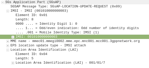
When a UE connects to the LTE RAN (EUTRAN) the MME signals the GSM/UMTS MSC with an SGsAP-LOCATION-UPDATE-REQUEST,
This request includes the IMSI of the subscriber that just attached and the FQDN of the MME serving that UE.
The MSC now knows that IMSI 001010000000003 is currently on LTE RAN served by MME mmec01.mmegi0002.mme.epc.mnc001.mcc001.3gppnetwork.org,
If a call or SMS comes into the MSC destined for the MSISDN of that IMSI, the MSC can page the UE on the LTE RAN to tell it to do an inter-RAN handover to GSM/UMTS.
Setting it Up
In order to get this working you’ll need OsmoMSC in place, your subscribers to exist on OsmoHLR and the LTE HSS – For example Open5GS-HSS.
Once you’ve done that the additional config on OsmoMSC is fairly simple, we just define a new SGs interface to listen on:
OsmoMSC Config:
sgs
  local-port 29118
  local-ip 0.0.0.0
  vlr-name vlr.msc001.mnc001.mcc001.3gppnetwork.org
end
On the Open5GS side we’ve got to include the SGs info the MME config. Keep in mind the Tracking Area Code (TAC) in LTE must exist as the Location Area code (LAC) in GSM, here’s an extract of the MME section of YAML config in the Open5GS MME config:
The EUTRAN will need to advertise the presence of it’s GERAN neighbours and vise-versa so the UE/terminals know what ARFCN to move to so they don’t need to scan for the presence of other RATs when performing the handover.
Setting this up will depend on your eNB / BSC and goes beyond the scope of this post.
I’ll cover setting up neighbours in a later post as it’s a big topic.
If you don’t have neighbours configured, the handover will still work but will be much slower as the UE will have to scan to find the serving cell it’s reselecting to.
So we’ve got a functional network, but let’s dive deeper into what we can do to connect it with other networks and how things work in “the real world”.
Media Handling – OsmoMGW
The Audio/Voice (media stream) data on a call between subscribers does not go directly between the subscribers and instead needs to be proxed relayed. The reason for this is because there’s no direct link from one BTS to another BTS (even if they are served by the same BSC) and as our subscribers can move from cell to cell while on a call – which may mean moving from one BSC to another depending on where they’re heading – we need to have a single point for the audio to remain.
To handle this a Media Gateway is used, a single point for call audio to be “anchored” – meaning regardless of which BTS/BSC is serving the subscribers on either end of the call, the media will be sent by both parties to a single destination (The Media Gateway), and that destination will send the audio to the other party.
The Media gateway relays / proxies the Media Stream – the RTP packets containing the call audio. OsmoMSC provides the SDP payload containing the codecs and RTP details for the session via MGCP (Media Gateway Control Protocol) to the OsmoMGW which relays the audio.
In terms of running osmo-mgw we installed it earlier,
The only parameter you really need to change is the rtp bind-ip,
On the MGW you can also limit and restrict the codecs supported and also allow or disallow transcoding.
MNCC-SAP & Call Routing
In it’s default mode, the OsmoMSC will look at the destination a call is being sent to, and if the destination is a subscriber on the network (in it’s VLR), will route the call to that subscriber
This on-net only mode is great but it puts our network on an island – cut off from the outside world.
Calls between MSCs, to the PSTN and users everywhere else are not possible in this scenario.
3GPP defined “MNCC-SAP” (Mobile Network Call Control – Service Access Point) a protocol for handling calls to/from destinations outside of the local MSC.
When in MNCC-SAP mode all calls (even on-net calls between subscribers on the same MSC) are routed to the external MNCC-SAP, and left up to it to determine how to route the call.
Configuring Osmo-MSC to talk MNCC
As we just covered by default Osmo-MSC only switches calls internally between subscribers, so we’ll need to turn off this behaviour and isntead reconfigure it to talk MNCC-SAP.
To do this we’ll telnet / VTY into Osmo-MSC;
root@gsm-bts:/etc/osmocom# telnet localhost 4254
Welcome to the OsmoMSC VTY interface
OsmoMSC - Osmocom Circuit-Switched Core Network implementation
OsmoMSC> enable
OsmoMSC# configure terminal
OsmoMSC(config)# msc
OsmoMSC(config-msc)# mncc external /tmp/msc_mncc
OsmoMSC(config-msc)# end
OsmoMSC# cop run st
Configuration saved to /etc/osmocom/osmo-msc.cfg
After making this change we have to restart OsmoMSC;
systemctl restart osmo-msc
Now OsmoMSC will not switch calls locally, but instead when a mobile originated call comes to the MSC, it will signal to the external MNCC via the file sock at /tmp/msc_mncc,
MNCC-SAP sounds great but platform X only speaks SIP
Enter the Osmo-SIP-Connector, which takes the MNCC-SAP messages and converts them to SIP.
From here you can tie the call control functions of the MNC into any SIP software such as Kamailio, FreeSwitch, Asterisk, etc, to handle call routing, number translation, application services like voicemail and conferencing, etc, etc.
On my to-do list is to make a call between one subscriber on GSM and one on VoLTE, I’ll cover that in a subsequent post.
So anywho, let’s get Osmo-SIP-Connector setup, I’m running it on the same box as the MSC on 10.0.1.201, My softphone client is running on 10.0.1.252
root@gsm-bts:/etc/osmocom# apt-get install osmo-sip-connector
root@gsm-bts:/etc/osmocom# telnet localhost 4256
Welcome to the OsmoSIPcon VTY interface
OsmoSIPcon> enable
OsmoSIPcon# configure t
OsmoSIPcon(config)# mncc
OsmoSIPcon(config-mncc)# socket-path /tmp/msc_mncc
OsmoSIPcon(config-mncc)# exit
OsmoSIPcon(config)# sip
OsmoSIPcon(config-sip)# local 10.0.1.201 5060
OsmoSIPcon(config-sip)# remote 10.0.1.252 5060
OsmoSIPcon(config-sip)# end
OsmoSIPcon# cop run st
Configuration saved to /etc/osmocom/osmo-sip-connector.cfg
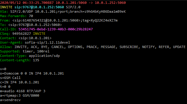
Now any Mobile Originated calls will result in a SIP INVITE being sent to 10.0.1.252 port 5060 (using UDP).
Any SIP INVITES where the request URI is a valid MSISDN @ 10.0.1.201 from 10.0.1.252 will be routed to the correct subscriber for that MSISDN.
A small note – The GSM codec is (unsurprisingly) used as the codec for GSM calls by default.
Some handsets support different codecs, but many off-the-shelf IP phones don’t include GSM support, so you may find you’re required to transcode between codecs if there is no support for the other codecs.
So now we’re able to define our call routing logic in something that speaks SIP and connect calls between multiple MSCs, VoLTE / IMS networks and fixed networks, all based on what we do with the SIP.
Local Call, Local Switch
If two subscribers on the same BSC call each other, the RTP / call audio will route to the MGW where it’s anchored.
This makes sense from a mobility standpoint, but adds load to the MGW and relies on a quality A interface connection, which may be an issue depending on what backhaul options you have.
Local Call, Local Switch is a 3GPP spec to allow the RTP / call audio to act as the RTP proxy instead of the MGW.