Tag Archives: UCCID

SIM / Smart Card Deep Dive – Part 3 – APDUs and Hello Card

In our last post we covered the file system structure of a smart card and the basic concepts of communication with cards. In this post we’ll look at what happens on the application layer, and how to interact with a card.

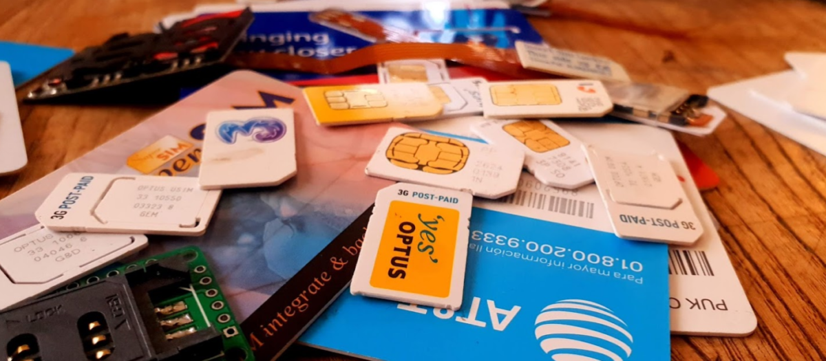
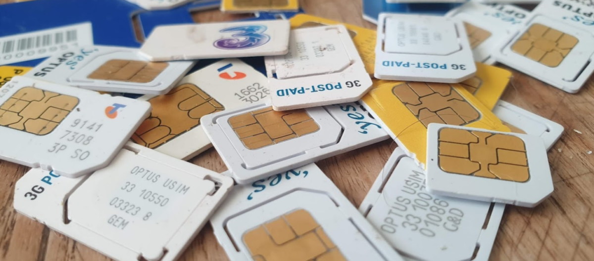
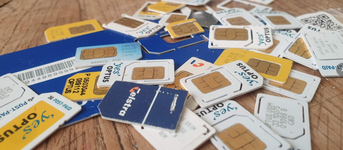
For these examples I’ll be using SIM cards, because admit it, you’ve already got a pile sitting in a draw, and this is a telco blog after all. You won’t need the ADM keys for the cards, we’ll modify files we’ve got write access to by default.

Commands & Instructions

So to do anything useful with the card we need issue commands / instructions to the card, to tell it to do things. Instructions like select this file, read it’s contents, update the contents to something else, verify my PIN, authenticate to the network, etc.

The term Command and Instruction are used somewhat interchangeably in the spec, I realise that I’ve done the same here to make it just as confusing, but instruction means the name of the specific command to be called, and command typically means the APDU as a whole.

The “Generic Commands” section of 3GPP TS 31.101 specifies the common commands, so let’s take a look at one.

The creatively named SELECT command/instruction is used to select the file we want to work with. In the SELECT command we’ll include some parameters, like where to find the file, so some parameters are passed with the SELECT Instruction to limit the file selection to a specific area, etc, the length of the file identifier to come, and the identifier of the file.

The card responds with a Status Word, returned by the card, to indicate if it was successful. For example if we selected a file that existed and we had permission to select, we’d get back a status word indicating the card had successfully selected the file. Status Words are 2 byte responses that indicate if the instruction was successful, but also the card has data it wants to send to the terminal as a result of the instruction, how much data the terminal should expect.

So if we just run a SELECT command, telling the card to select a file, we’ll get back a successful response from the card with a data length. Next need to get that data from the card. As the card can’t initiate communication, the GET RESPONSE instruction is sent to the card to get the data from the card, along with the length of the data to be returned.

The GET RESPONSE instruction/command is answered by the card with an APDU containing the data the card has to send, and the last 2 bytes contain the Status Word indicating if it was successful or not.

APDUs

So having covered the physical and link layers, we now move onto the Application Layer – where the magic happens.

Smart card communications is strictly master-slave based when it comes to the application layer.

The terminal sends a command to the card, which in turn sends back a response. Command -> Response, Command -> Response, over and over.

These commands are contained inside APplication Data Units (APDUs).

So let’s break down a simple APDU as it appears on the wire, so to speak.

The first byte of our command APDU is taken up with a header called the class byte, abbreviated to CLA. This specifies class coding, secure messaging options and channel options.

In the next byte we specify the Instruction for the command, that’s the task / operation we want the card to perform, in the spec this is abbreviated to INS.

The next two bytes, called P1 & P2 (Parameter 1 & Parameter 2) specify the parameters of how the instruction is to be to be used.

Next comes Lc – Length of Command, which specifies the length of the command data to follow,

Data comes next, this is instruction data of the length specified in Lc.

Finally an optional Le – Length of expected response can be added to specify how long the response from the card should be.

Crafting APDUs

So let’s encode our own APDU to send to a card, for this example we’ll create the APDU to tell the card to select the Master File (MF) – akin to moving to the root directory on a *nix OS.

For this we’ll want a copy of ETSI TS 102 221 – the catchily named “Smart cards; UICC-Terminal interface; Physical and logical characteristics” which will guide in the specifics of how to format the command, because all the commands are encoded in hexadecimal format.

So here’s the coding for a SELECT command from section 11.1.1.1 “SELECT“,

For the CLA byte in our example we’ll indicate in our header that we’re using ISO 7816-4 encoding, with nothing fancy, which is denoted by the byte A0.

For the next but we’ve got INS (Instruction) which needs to be set to the hex value for SELECT, which is represented by the hex value A4, so our second byte will have that as it’s value.

The next byte is P1, which specifies “Selection Control”, the table in the specification outlines all the possible options, but we’ll use 00 as our value, meaning we’ll “Select DF, EF or MF by file id”.

The next byte P2 specifies more selection options, we’ll use “First or only occurrence” which is represented by 00.

The Lc byte defines the length of the data (file id) we’re going to give in the subsequent bytes, we’ve got a two byte File ID so we’ll specify 2 (represented by 02).

Finally we have the Data field, where we specify the file ID we want to select, for the example we’ll select the Master File (MF) which has the file ID ‘3F00‘, so that’s the hex value we’ll use.

So let’s break this down;

CodeMeaningValue
CLAClass bytes – Coding optionsA0 (ISO 7816-4 coding)
INSInstruction (Command) to be calledA4 (SELECT)
P1Parameter 1 – Selection Control (Limit search options)00 (Select by File ID)
P2Parameter 1 – More selection options00 (First occurrence)
LcLength of Data 02 (2 bytes of data to come)
DataFile ID of the file to Select3F00 (File ID of master file)

So that’s our APDU encoded, it’s final value will be A0 A4 00 00 02 3F00

So there we have it, a valid APDU to select the Master File.

In the next post we’ll put all this theory into practice and start interacting with a real life SIM cards using PySIM, and take a look at the APDUs with Wireshark.

SIM / Smart Card Deep Dive – Part 2 – Meet & Greet

Layer 1 – Pinout and Connections

Before we can get all excited about talking to cards, let’s look at how we interface with them on a physical level.

For “Classic” smart cards interface is through the fingernail sized contacts on the card.

As you’d expect there’s a VCC & Ground line for powering the card, a clock input pin for clocking it and a single I/O pin.

ISO/IEC 7816-3 defines the electrical interface and transmission protocols.

The pins on the terminal / card reader are arranged so that when inserting a card, the ground contact is the first contact made with the reader, this clever design consideration to protect the card and the reader from ESD damage.

Operating Voltages

When Smart Cards were selected for use in GSM for authenticating subscribers, all smart cards operated at 5v. However as mobile phones got smaller, the operating voltage range became more limited, the amount of space inside the handset became a premium and power efficiency became imperative. The 5v supply for the SIM became a difficult voltage to provide (needing to be buck-boosted) so lower 3v operation of the cards became a requirement, these cards are referred to as “Class B” cards. This has since been pushed even further to 1.8v for “Class C” cards.

If you found a SIM from 1990 it’s not going to operate in a 1.8v phone, but it’s not going to damage the phone or the card.

The same luckily goes in reverse, a card designed for 1.8v put into a phone from 1990 will work just fine at 5v.

This is thanks to the class flag in the ATR response, which we’ll cover later on.

Clocks

As we’re sharing one I/O pin for TX and RX, clocking is important for synchronising the card and the reader. But when smart cards were initially designed the clock pin on the card also served as the clock for the micro controller it contained, as stable oscillators weren’t available in such a tiny form factor. Modern cards implement their own clock, but the clock pin is still required for synchronising the communication.

I/O Pin

The I/O pin is used for TX & RX between the terminal/phone/card reader and the Smart Card / SIM card. Having only one pin means the communications is half duplex – with the Terminal then the card taking it in turns to transmit.

Reset Pin

Resets the card’s communications with the terminal.

Filesystem

So a single smart card can run multiple applications, the “SIM” is just an application, as is USIM, ISIM and any other applications on the card.

These applications are arranged on a quasi-filesystem, with 3 types of files which can be created, read updated or deleted. (If authorised by the card.)

Because the file system is very basic, and somewhat handled like a block of contiguous storage, you often can’t expand a file – when it is created the required number of bytes are allocated to it, and no more can be added, and if you add file A, B and C, and delete file B, the space of file B won’t be available to be used until file C is deleted.

This is why if you cast your mind back to when contacts were stored on your phone’s SIM card, you could only have a finite number of contacts – because that space on the card had been allocated for contacts, and additional space can no longer be allocated for extra contacts.

So let’s take a look at our 3 file types:

MF (Master File)

The MF is like the root directory in Linux, under it contains all the files on the card.

DF (Dedciated File)

An dedicated file (DF) is essentially a folder – they’re sometimes (incorrectly) referred to as Directory Files (which would be a better name).

They contain one or more Elementary Files (see below), and can contain other DFs as well.

Dedicated Files make organising the file system cleaner and easier. DFs group all the relevant EFs together. 3GPP defines a dedicated file for Phonebook entries (DFphonebook), MBMS functions (DFtv) and 5G functions (DF5gs).

We also have ADFs – Application Dedicated Files, for specific applications, for example ADFusim contains all the EFs and DFs for USIM functionality, while ADFgsm contains all the GSM SIM functionality.

The actual difference with an ADF is that it’s not sitting below the MF, but for the level of depth we’re going into it doesn’t matter.

DFs have a name – an Application Identifier (AID) used to address them, meaning we can select them by name.

EF (Elementary File)

Elementary files are what would actually be considered a file in Linux systems.

Like in a Linux file systems EFs can have permissions, some EFs can be read by anyone, others have access control restrictions in place to limit who & what can access the contents of an EF.

There are multiple types of Elementary Files; Linear, Cyclic, Purse, Transparent and SIM files, each with their own treatment by the OS and terminal.

Most of the EFs we’ll deal with will be Transparent, meaning they ##

ATR – Answer to Reset

So before we can go about working with all our files we’ll need a mechanism so the card, and the terminal, can exchange capabilities.

There’s an old saying that the best thing about standards is that there’s so many to choose, from and yes, we’ve got multiple variants/implementations of the smart card standard, and so the card and the terminal need to agree on a standard to use before we can do anything.

This is handled in a process called Answer to Reset (ATR).

When the card is powered up, it sends it’s first suggestion for a standard to communicate over, if the terminal doesn’t want to support that, it just sends a pulse down the reset line, the card resets and comes back with a new offer.

If the card offers a standard to communicate over that the terminal does like, and does support, the terminal will send the first command to the card via the I/O line, this tells the card the protocol preferences of the terminal, and the card responds with it’s protocol preferences. After that communications can start.

Basic Principles of Smart Cards Communications

So with a single I/O line to the card, it kind of goes without saying the communications with the card is half-duplex – The card and the terminal can’t both communicate at the same time.

Instead a master-slave relationship is setup, where the smart card is sent a command and sends back a response. Command messages have a clear ending so the card knows when it can send it’s response and away we go.

Like most protocols, smart card communications is layered.

At layer 1, we have the physical layer, defining the operating voltages, encoding, etc. This is standardised in ISO/IEC 7816-3.

Above that comes our layer 2 – our Link Layer. This is also specified in ISO/IEC 7816-3, and typically operates in one of two modes – T0 or T1, with the difference between the two being one is byte-oriented the other block-oriented. For telco applications T0 is typically used.

Our top layer (layer 7) is the application layer. We’ll cover the details of this in the next post, but it carries application data units to and from the card in the form of commands from the terminal, and responses from the card.

Coming up Next…

In the next post we’ll look into application layer communications with cards, the commands and the responses.

SIM / Smart Card Deep Dive – Part 1 – Introduction to Smart Cards

I know a little bit about SIM cards / USIM cards / ISIM Cards.
Enough to know I don’t know very much about them at all.

So throughout this series of posts of unknown length, I’ll try and learn more and share what I’m learning, citing references as much as possible.

So where to begin? I guess at the start,

A supposedly brief history of Smart Cards

There are two main industries that have driven the development and evolution of smart cards – telecom & banking / finance, both initially focused on the idea that carrying cash around is unseemly.

This planet has – or rather had – a problem, which was this: most of the people living on it were unhappy for pretty much of the time. Many solutions were suggested for this problem, but most of these were largely concerned with the movement of small green pieces of paper, which was odd because on the whole it wasn’t the small green pieces of paper that were unhappy.

Douglas Adams – The Hitchhiker’s Guide to the Galaxy

When the idea of Credit / Debit Cards were first introduced the tech was not electronic, embossed letters on the card were fed through that clicky-clacky-transfer machine (Google tells me this was actually called the “credit card imprinter”) and the card details imprinted onto carbon copy paper.

Customers wanted something faster, so banks delivered magnetic strip cards, where the card data could be read even more quickly, but as the security conscious of you will be aware, storing data on magnetic strips on a card to be read by any reader, allows them to be read by any reader, and therefore duplicated really easily, something the banks quickly realised.

To combat this, card readers typically would have a way to communicate back to a central bank computer. The central computer verified the PIN entered by the customer was correct, confirmed that the customer had enough money in their balance for the transaction and it wasn’t too suspicious. This was, as you would imagine in the late 1980’s early 1990’s, rather difficult to achieve. A reliable (and cheap) connection back to a central bank computer wasn’t always a given, nor instant, and so this was still very much open to misuse.

“Carders” emmerged, buying/selling/capturing credit card details, and after programming a blank card with someone else’s fraudulently obtained card details, could write them on a blank card before going on a spending spree for a brief period of time. Racking up a giant debt that wasn’t reconciled against the central computer until later, when the card was thrown away and replaced with another.

I know what you’re thinking – I come to this blog for ramblings about Telecommunications, not the history of the banking sector. So let’s get onto telco;

The telecom sector faced similar issues, at the time mobile phones were in their infancy, and so Payphones were how people made calls when out and about.

A phone call from a payphone in Australia has sat at about $0.40 for a long time, not a huge amount, but enough you’d always want to be carrying some change if you wanted to make calls. Again, an inconvenience for customers as coins are clunky, and an inconvenience for operators as collecting the coins from tens of thousands of payphones is expensive.

Telcos around the world trailed solutions, including cards with magnetic strips containing the balance of the card, but again people quickly realised that you could record the contents of the magnetic stripe data of the card when it had a full balance, use all the balance on the card, and then write back the data you stored earlier with a full balance.

So two industries each facing the same issue: it’s hard to securely process payments offline in a way that can’t be abused.

Enter the smart card – a tiny computer in a card that the terminal (Payphone or Credit Card Reader) interacts with, but the card is very much in charge.

When used in a payphone, the caller inserts the smart card and dials the number, and dialog goes something like this (We’ll assume Meter Pulses are 40c worth):

Payphone: “Hey SmartCard, how much credit do you have on you?”

Smart Card: “I have $1.60 balance”

*Payphone ensures card has enough credit for the first meter pulse, and begins listening for Meter Pulses*

*When a meter pulse received:*

Payphone: “Please deduct $0.40 from your Balance”

Smart Card: “Ok, you have $1.20 remaining”

This process repeats for each meter pulse (Payphone metering is a discussion for another day) until all the credit has been used / Balance is less than 1 meter pulse charge.

While anyone could ask the smart card “Hey SmartCard, how much credit do you have on you?” it would only return the balance, and if you told the smart card “I used $1 credit, please deduct it” like the payphone did, you’d just take a dollar off the credit stored on the card.

Saying “Hey SmartCard set the balance to $1,000,000” would result in a raised eyebrow from the SmartCard who rejects the request.

After all – It’s a smart card. It has the capability to do that.

So in the telecom sector single use smart cards were rolled out, programmed in the factory with a set dollar value of credit, sold at that dollar value and thrown away when depleted.

The banking industry saw even more potential, balance could be stored on the card, and the PIN could be verified by the card, the user needs to know the correct PIN, as does the smart card, but the terminal doesn’t need to know this, nor does it need to talk back to a central bank computer all the time, just every so often so the user gets the bill.

It worked much the same way, although before allowing a deduction to be made from the balance of the card, a user would have to enter their PIN which was verified by the card before allowing the transaction.

Eventually these worlds collided (sort of), both wanting much the same thing from smart cards. So the physical characteristics, interface specs (rough ones) and basic communications protocol was agreed on, and what eventually became ISO/IEC 7816 was settled upon.

Any card could be read by any terminal, and it was up to the systems implementer (banks and telecos initially) what data the card did and what the terminal did.

Active RFID entered the scene and there wasn’t even a need for a physical connection to the card, but the interaction was the same. We won’t really touch on the RFID side, but all of this goes for most active RFID cards too.

Enter Software

Now the card was a defined standard all that was important really was the software on the card. Banks installed bank card software on their cards, while telcos installed payphone card software on theirs.

But soon other uses emerged, ID cards could provide a verifiable and (reasonably) secure way to verify the card’s legitimacy, public transport systems could store commuter’s fares on the card, and vending machines, time card clocks & medical records could all jump on the bandwagon.

These were all just software built on the smart card platform.

Hello SIM Cards

A early version Smart card was used in the German C-Netz cellular network, which worked in “mobile” phones and also payphones, to authenticate subscribers.

After that the first SIM cards came into the public sphere in 1991 with GSM as a way to allow a subscriber’s subscription to be portable between devices, and this was standardised by ETSI to become the SIM cards still used in networks using GSM, and evolved into the USIM used in 3G/4G/5G networks.

Names of Smart Cards & Readers

To make life a bit easier I thought I’d collate all the names for smart cards and readers that are kind of different but used interchangeably depending on the context.

Smart Card|Terminal
UICC (Universal Integrated Circuit Card) – Standards name for Smart CardCard Reader (Generic)
SIM (Mobile Telco application running on UICC)Phone (Telco)
USIM (Mobile Telco application running on UICC)SIM Slot (Telco)
Credit / Debit / EFTPOS Card (Banking)UE (Telco)
Java Card (Type of Smart Card OS)EFTPOS Terminal (Banking)
Phone Card (Telco / Payphone)

And then…

From here we’ll look at various topics:

  • Introduction to Smart Cards (This post)
  • Meet & Greet (The basics of Smart Cards & their File System)
  • APDUs and Hello Card (How terminals interact with a smart cards)
  • (Interacting with real life cards using Smart Card readers and SIM cards)
  • Mixing It Up (Changing values on Cards)

Other topics we may cover are Javacard and Global Platform, creating your own smart card applications, a deeper look at the different Telco apps like SIM/USIM/ISIM, OTA Updates for cards / Remote File Management (RFM), and developing for SimToolkit.

Magic SIM Card Art

16 in 1 Magic SIM Card Revisited

I found a “16-in-1 Super SIM X-SIM” in my SIM card drawer, I think I ordered these when I was first playing with GSM and never used it.

I was kind of curious about how these actually worked, so after some online sleuthing I found a very suspicious looking rar file, which I ended up running in a VM and mapping the Card Reader to the VM.

What a treat I was in for in terms of UI.

The concept is quite simple, you program a series of IMSI and K key values onto the SIM card, and then using a SIM Toolkit application, you’re able to select which IMSI / K key combination you want to use.

A neat trick, I’d love a LTE version of this for changing values on the fly, but it’d be a pretty niche item considering no operator is going to give our their K and OPc keys,

But come to think of it, no GSM operator would give out K keys, so how do you get the K key from your commercial operator?

I noticed the grayed out “Crack” icon on the menu.

After rifling through my SIM drawer I found a few really old 2G SIMs, stuck one in, reconnected and clicked “Crack” and then start.

I left it running in the background after the manual suggested it could take up to 24 hours to run through all the codes.

To my surprise after 2 minutes the software was requesting I save the exported data, which I did.

Then I put the 16 in 1 back in, selected Magic and then imported the cracked SIM data (IMSI, ICCID, Ki & SMSp).

By the looks of it the software is just running a brute force attack on the SIM card, and the keyspace is only so large meaning it can be reversed in.

I did a bit of research to find out if this is exploiting any clever vulnerabilities in UCCID cards, but after running some USB Pcap traces it looks like it’s just plain old brute force, which could be easily defended against by putting a pause between auth attempts on the SIM.

I’ve no idea if that’s the actual K value I extracted from the SIM – The operator that issued the SIM doesn’t even exist anymore, but I’ll add the details to the HLR of my Osmocom GSM lab and see if it matches up.

Out of curiosity I also connected some of my development USIM/ISIM/SIM cards that I can program, the software is amazing in it’s response: