Tag Archives: TIED

Getting TEID up with GTP Tunnels

If you’re using an GSM / GPRS, UMTS, LTE or NR network, there’s a good chance all your data to and from the terminal is encapsulated in GTP.

GTP encapsulates user’s data into a GTP PDU / packet that can be redirected easily. This means as users of the network roam around from one part of the network to another, the destination IP of the GTP tunnel just needs to be updated, but the user’s IP address doesn’t change for the duration of their session as the user’s data is in the GTP payload.

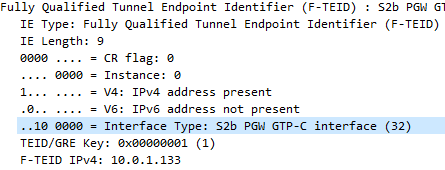
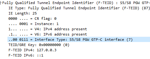
One thing that’s a bit confusing is the TEID – Tunnel Endpoint Identifier.

Each tunnel has a sender TEID and transmitter TEID pair, as setup in the Create Session Request / Create Session Response, but in our GTP packet we only see one TEID.

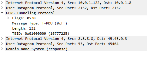
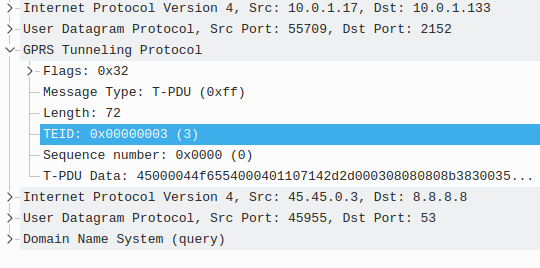
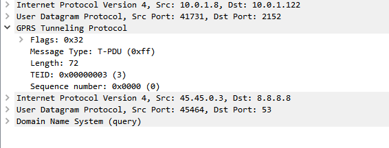
There’s not much to a GTP-U header; at 8 bytes in all it’s pretty lightweight. Flags, message type and length are all pretty self explanatory. There’s an optional sequence number, the TEID value and the payload itself.

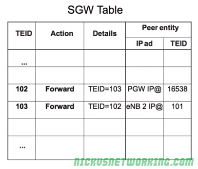
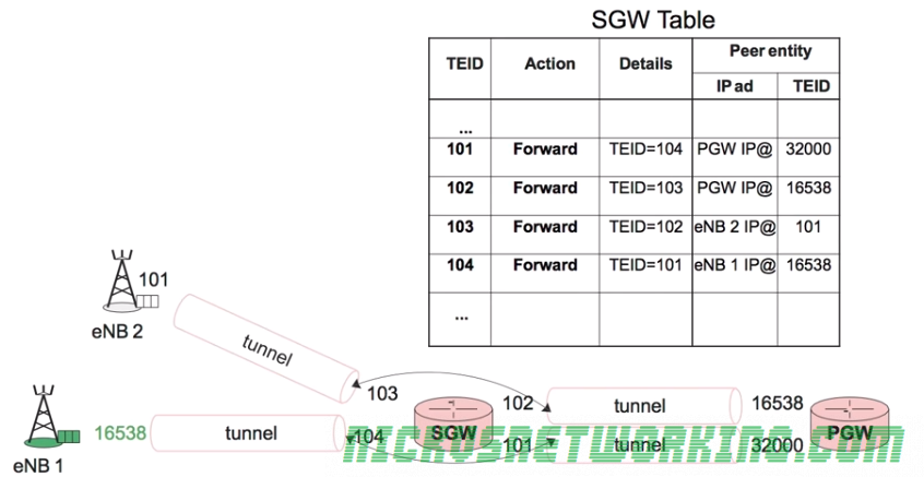
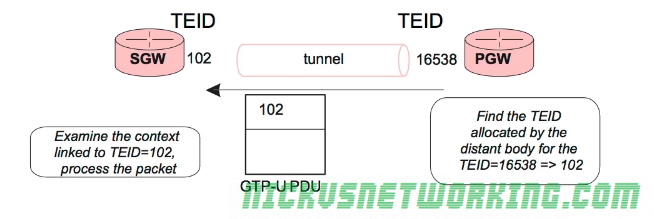
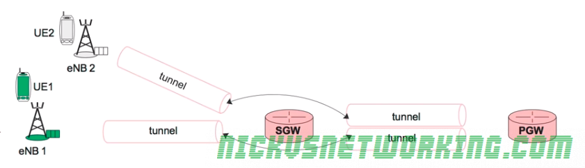
So the TEID identifies the tunnel, but it’s worth keeping in mind that the TEID only identifies a data flow from one Network Element to another, for example eNB to S-GW would have one TEID, while S-GW to P-GW would have another TEID.

Each tunnel has two TEIDs, a sending TEID and a receiving TEID. For some reason (Minimize overhead on backhaul maybe?) only the sender TEID is included in the GTP header;

This means a packet that’s coming from a mobile / UE will have one TEID, while a packet that’s going to the same mobile / UE will have a different TEID.

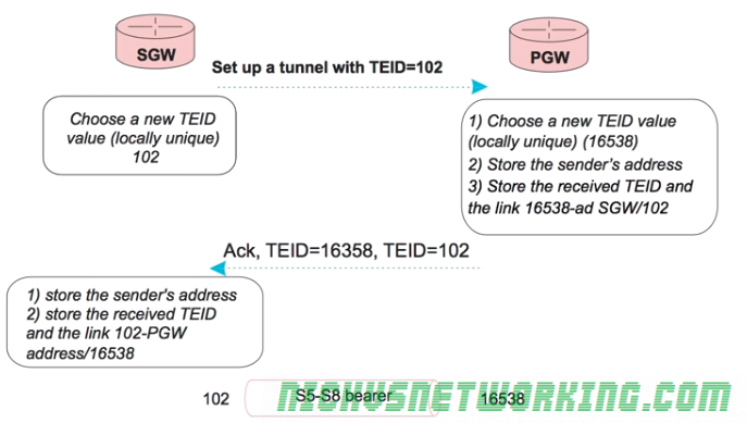
Mapping out TIEDs is typically done by looking at the Create Session Request / Responses, the Create Session Request will have one TIED, while the Create Session Response will have a different TIED, thus giving you your TIED pair.

GTPv2 – F-TEID Interface Types

I’ve been working on a ePDG for VoWiFi access to my IMS core.

This has led to a bit of a deep dive into GTP (easy enough) and GTPv2 (Bit harder).

The Fully Qualified Tunnel Endpoint Identifier includes an information element for the Interface Type, identified by a two digit number.

Here we see S2b is 32

In the end I found the answer in 3GPP TS 29.274, but thought I’d share it here.

0S1-U eNodeB GTP-U interface
1S1-U SGW GTP-U interface
2S12 RNC GTP-U interface
3S12 SGW GTP-U interface
4S5/S8 SGW GTP-U interface
5S5/S8 PGW GTP-U interface
6S5/S8 SGW GTP-C interface
7S5/S8 PGW GTP-C interface
8S5/S8 SGW PMIPv6 interface (the 32 bit GRE key is encoded in 32 bit TEID field and since alternate CoA is
not used the control plane and user plane addresses are the same for PMIPv6)
9S5/S8 PGW PMIPv6 interface (the 32 bit GRE key is encoded in 32 bit TEID field and the control plane and
user plane addresses are the same for PMIPv6)
10S11 MME GTP-C interface
11S11/S4 SGW GTP-C interface
12S10 MME GTP-C interface
13S3 MME GTP-C interface
14S3 SGSN GTP-C interface
15S4 SGSN GTP-U interface
16S4 SGW GTP-U interface
17S4 SGSN GTP-C interface
18S16 SGSN GTP-C interface
19eNodeB GTP-U interface for DL data forwarding
20eNodeB GTP-U interface for UL data forwarding
21RNC GTP-U interface for data forwarding
22SGSN GTP-U interface for data forwarding
23SGW GTP-U interface for DL data forwarding
24Sm MBMS GW GTP-C interface
25Sn MBMS GW GTP-C interface
26Sm MME GTP-C interface
27Sn SGSN GTP-C interface
28SGW GTP-U interface for UL data forwarding
29Sn SGSN GTP-U interface
30S2b ePDG GTP-C interface
31S2b-U ePDG GTP-U interface
32S2b PGW GTP-C interface
33S2b-U PGW GTP-U interface

I also found how this data is encoded on the wire is a bit strange,

In the example above the Interface Type is 7,

This is encoded in binary which give us 111.

This is then padded to 6 bits to give us 000111.

This is prefixed by two additional bits the first denotes if IPv4 address is present, the second bit is for if IPv6 address is present.

Bit 1Bit 2Bit 3-6
IPv4 Address Present IPv4 Address PresentInterface Type
11 000111

This is then encoded to hex to give us 87

Here’s my Python example;

interface_type = int(7)
interface_type = "{0:b}".format(interface_type).zfill(6)   #Produce binary bits
ipv4ipv6 = "10" #IPv4 only
interface_type = ipv4ipv6 + interface_type #concatenate the two
interface_type  = format(int(str(interface_type), 2),"x") #convert to hex

IMTx: NET02x (4G Network Essentials) – Management of Data Flows – 7. NAS and Global View of Protocol Stack

These are my lecture notes from IMT’s NET02x (4G Network Essentials) course, I thought I’d post them here as they may be useful to someone. You can find my complete notes here.

The LTE architecture compartmentalises the roles in the mobile network.

For example the eNB concentrates on radio connection management, while the MME focuses on security and mobility.

Non Access Stratum (NAS) messages are exchanged between the terminal and the MME.

Access Stratum (AS) messages are exchanged over the air between the UE and the eNB. It contains all the radio related information.

The eNB must map the NAS messages from an MME to a LCID and RNTI and transmit them over the air, and vice-versa. The eNB forwards this data without ever analyzing it.

Transport of S1 messages is carried over SCTP which I’ve spoken about in the past.

The above image overlaps with the radio version we talked about earlier.

IMTx: NET02x (4G Network Essentials) – Management of Data Flows – 5/6. S1AP Connection

These are my lecture notes from IMT’s NET02x (4G Network Essentials) course, I thought I’d post them here as they may be useful to someone. You can find my complete notes here.

Each MME can manage millions of UEs.

To handle this load the requirements of each subscriber for the MME must be as minimal and simple as possible so as to scale easily.

For each UE in the network a connection is setup between the UE and the MME.

This is done over the S1-AP’s Control Plane interface (sometimes calls S1-Control Plane or S1-CP) which carries control plane data to & from the UE via the eNB to the MME.

S1-CP is connection-oriented, meaning each UE has it’s own connection to the MME, so there are as many S1-CP connections to the MME as UE’s connected.

Each of these S1-CP connections is identified by a pair of unique connection IDs. The eNB keeps track of the connection IDs for each UE connected and hands this information off each time the UE moves to a different eNB.

The eNB keeps a lookup table between the RNTI of the UE and the LCID – the Logical Channel Identifier. This means that the eNB knows the sent and received ID of the S1-CP connection for each UE, and is able to translate that into the RNTI and LCID used to send the data over the air interface to the UE.

S1-CP Connect (Attach Procedure)

As we discussed in radio interfaces, when a UE connects to the network it is assigned an RNTI to identify it on the radio interface and allocate radio resources to it.

Once the RNTI is confirmed by both the eNB and the UE, a EMM Attach Request, which is put into an RRC Message called RRCConnectionSetupComplete.

The eNB must next choose a serving MME for this UE. It picks one based on it’s defined logic, and sends a S1-AP Intial UE Message (EMM Attach Request) to the MME along with the eNB’s connection identity assigned for this connection.

The MME stores the connection identity assigned by the eNB and chooses it’s own connection identity for it’s side, and sends back an S1AP Downlink NAS Transport response with both connection identities and the response for the attach request (This will be an EMM Authentication Request).

The eNB then stores the connection identity pair and the associated RNTI and LCID for the UE, and forwards the EMM Authentication Request to the RNTI of the UE via RRC.

The UE will pass the authentication challenge input parameters to the USIM which will generate a response. The UE will send the output of this response in a EMM Authentication Responseto the eNB, which will look at the RNTI and LCID received and consult the table to find the Connection Identifiers and IP of the serving MME for this UE.

S1AP Connect procedure

IMTx: NET02x (4G Network Essentials) – Management of Data Flows – 4. Transmitting Packets in a Tunnel

These are my lecture notes from IMT’s NET02x (4G Network Essentials) course, I thought I’d post them here as they may be useful to someone. You can find my complete notes here.

Establishing a GTP Tunnel

When a new tunnel is setup between two nodes, GTP-C will be used to setup the tunnel and the both ends of the tunnel will allocate a their own locally unique TEID to the tunnel.

Let’s take a look at setting up a GTP tunnel between a S-GW and a P-GW, initiated by the S-GW.

The process will start with the S-GW sending the P-GW a GTP-C tunnel establishment request and include the TEID the S-GW has allocated for it’s end of the tunnel (using TEID 102 in this example), sent from the S-GW to the P-GW.

The P-GW will receive this packet. When it does it will allocate a new TEID for this tunnel for it’s side (In this case it’s 16538), store the sender’s address and received TEID, and link local TEID 16538 with S-GW/102.

An ACK is sent from the P-GW to the S-GW with both TEID values.

Finally the S-GW stores the senders’ address, the received TEID and the link 102-PGW address 16538.


Now the exchange is complete the S-GW and the P-GW each know the TEID of it’s local side of the tunnel, and the remote side of the tunnel.

TEID Management Tables

After GTP tunnels are setup a management table is populated defining the forward rules for that traffic.

For example a packet coming in on TEID 103 would, according to the table forward to TEID 102. TEID 102 sends traffic to the P-GW’s IP using remote TEID 16538.

The same rules for uplink are applied for downlink.

Each tunnel has pair of TEIDs a local TEID and a remote TEID.

Because it’s such a simple table it can be updated very easily and scales well.

Different QoS parameters can be assigned to each tunnel, called a data bearer.

IMTx: NET02x (4G Network Essentials) – Management of Data Flows – 3. Identifying & Managing Tunnels

These are my lecture notes from IMT’s NET02x (4G Network Essentials) course, I thought I’d post them here as they may be useful to someone. You can find my complete notes here.

As we’ve talked about traffic to and from UEs is encapsulated in GTP-U tunnels, with the idea that by encapsulating data destined for a UE it can be routed to the correct destination (eNB serving UE) transparently and efficiently.

As all traffic destined for a UE will come to the P-GW, the P-GW must be able to quickly determine which eNB and S-GW to send the encapsulated data too.

The encapsulated data is logically grouped into tunnels between each node.

A GTP tunnel exists between the S-GW and the P-GW, another GTP tunnel exists between the S-GW and the eNB.

Each tunnel between the eNB and the S-GW, and each tunnel between S-GW and P-GW, is allocated a unique 32 bit value called a Tunnel Endpoint Identifier (TEID) allocated by the node that corresponds to each end of the tunnel and each TEID is locally unique to that node.

For each packet of user data (GTP-U) sent through a GTP tunnel the TEID allocated by the receiver is put in the GTP header by the sender.

The destinations of the tunnels can be updated, for example if a UE moves to a different eNB, the tunnel between the S-GW and the eNB can be quickly updated to point at the new eNB.

If the UE moves to a different eNB only the tunnel between the S-GW and the eNB needs to be updated

Each end of the tunnel is associated with a TEID, and each time a GTP packet is sent through the tunnel it includes the TEID of the remote end (reciever) in the GTP header.