Note: I’m running version 19.12.0 which I installed from the repos due to issues with 20.4.0 (latest when I wrote this) and stability on LimeSDR.
I wrote the other day about installing SRS LTE stack,
But installing it is one thing, meeting all the requirements to use it with your SDR hardware turns out to be another whole thing all together.
srsENB is a software defined eNodeB, allowing you to use a Software Defined Radio to serve as an eNodeB, UE and a few other utilities.
SRS’ implementation of the eNB is supposed to be 3GPP R10 compliant and supports eMBMS to boot.
Meeting Dependencies
Installing prerequisites
I’m using a LimeSDR, but these instructions also for for the BladeRF. I found the frequency stability of my BladeRF X40 wasn’t great, meaning when running SRS’s eNodeB the cell wasn’t visible to my UE.
sudo apt install tree vim git g++ make cmake pkg-config python-numpy swig libi2c-dev libusb-1.0-0-dev libfftw3-dev libmbedtls-dev libboost-program-options-dev libconfig++-dev libsctp-dev gnuradio
Install SoapySDR from Source
git clone https://github.com/pothosware/SoapySDR.git
pushd SoapySDR
git checkout tags/soapy-sdr-0.7.2 -b soapy-sdr-0.7.2
mkdir build
cd build
cmake ..
make
sudo make install
sudo ldconfig
popd
Install LimeSuite
You can skip this if you’re using a BladeRF
git clone https://github.com/myriadrf/LimeSuite.git
pushd LimeSuite
#git checkout tags/v19.04.0 -b v19.04.0
mkdir builddir
cd builddir
cmake ..
make
sudo make install
sudo ldconfig
cd ../udev-rules
sudo sh ./install.sh
popd
Install BladeRF
You can skip this if using a LimeSDR
git clone https://github.com/Nuand/bladeRF.git
pushd bladeRF/host/
mkdir build
cd build/
cmake -DCMAKE_BUILD_TYPE=Release -DCMAKE_INSTALL_PREFIX=/usr/local -DINSTALL_UDEV_RULES=ON -DBLADERF_GROUP=plugdev ..
make
sudo make install
sudo ldconfig
sudo mkdir -p /etc/Nuand/bladeRF/
sudo wget https://www.nuand.com/fpga/hostedx40-latest.rbf --output-document /etc/Nuand/bladeRF/hostedx40.rbf
popd


git clone https://github.com/pothosware/SoapyBladeRF.git
pushd SoapyBladeRF
mkdir build
cd build
cmake ..
make
sudo make install
popd
Install SRS GUI
(Optional but makes life easier and has to be done prior to installing SRSLTE)
sudo apt-get install libboost-system-dev libboost-test-dev libboost-thread-dev libqwt-qt5-dev qtbase5-dev
git clone https://github.com/srsLTE/srsGUI.git
pushd srsGUI
mkdir build
cd build
cmake ..
make
sudo make install
popd
Install SRSLTE (SRSenb & SRSue)
pushd srsLTEmkdir build cd build cmake ../ make make test sudo make install sudo ldconfig sudo ./srslte_install_configs.sh service popd
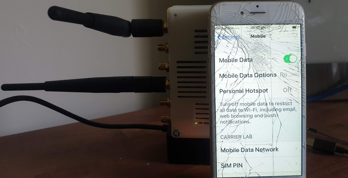
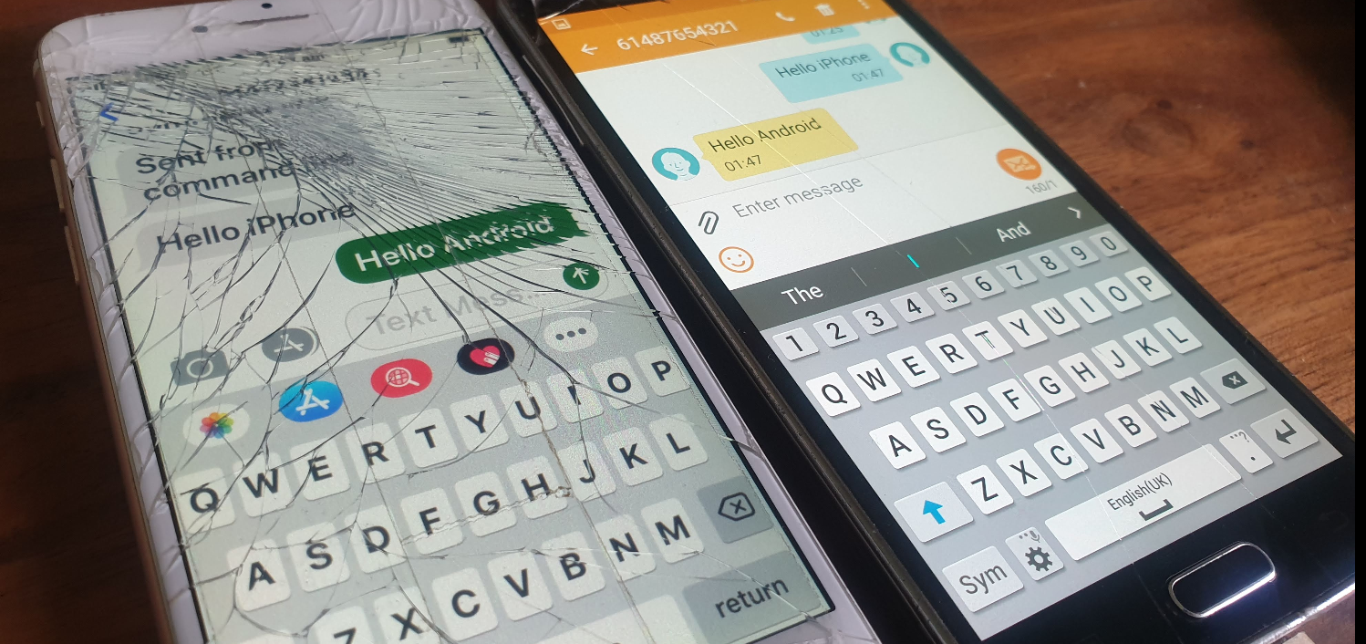
One nifty feature of this interface is that you can send SMS using the MSC to switch the SMS traffic and the LTE/EUTRAN to transfer the messaging.
This means you don’t need Circuit Switched Fallback to send or receive SMS on LTE.
I assume this functionality was added to avoid the signalling load of constantly changing RAN technologies each time a subscriber sent or received an SMS, but I couldn’t find much about it’s history.
In order to get this to work you’ll essentially need the exact same setup I outlined in my CSFB example (Osmo-MSC, Osmo-STP, Osmo-HLR populated with the IMSI and MSISDN values you want to use for SMS), although you won’t actually need a GERAN / GSM radio network.
Once that’s in place you can just send SMS between subscribers,
Plus from the VTY terminal of OsmoMSC you can send SMS too:
I’ve talked about how LTE’s EUTRAN / EPC has no knowledge about voice calls or SMS and instead relies on IMS/VoLTE for these services.
Circuit Switched Fallback allows UEs to use a 2G or 3G network (Circuit Switched network) if their device isn’t connected to the IMS network to make calls as the 2G/3G network can handle the voice call or SMS routing via the Mobile Switching Center in the 2G/3G network.
However for incoming calls destined to the UE (Mobile Terminated) the MSC needs a way to keep track of which MME is serving the UE so it can get a message to the MME and the MME can relay it to the UE, to tell it to drop to a 2G or 3G network (Circuit Switched network).
The signalling between the MME (In the LTE EPC) and the MSC (In the GSM/UTRAN core) is done over the SGs interface.
While the SGs interface is primarily for managing user location state across multiple RAN types, it’s got a useful function for sending SMS over SGi, allowing users on an LTE RAN to send SMS via the MSC of the 2G/3G network (GSM/UTRAN core).
How it Works:
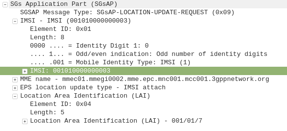
When a UE connects to the LTE RAN (EUTRAN) the MME signals the GSM/UMTS MSC with an SGsAP-LOCATION-UPDATE-REQUEST,
This request includes the IMSI of the subscriber that just attached and the FQDN of the MME serving that UE.
The MSC now knows that IMSI 001010000000003 is currently on LTE RAN served by MME mmec01.mmegi0002.mme.epc.mnc001.mcc001.3gppnetwork.org,
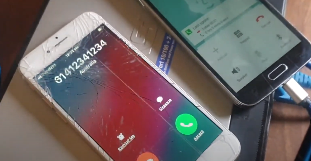
If a call or SMS comes into the MSC destined for the MSISDN of that IMSI, the MSC can page the UE on the LTE RAN to tell it to do an inter-RAN handover to GSM/UMTS.
Setting it Up
In order to get this working you’ll need OsmoMSC in place, your subscribers to exist on OsmoHLR and the LTE HSS – For example Open5GS-HSS.
Once you’ve done that the additional config on OsmoMSC is fairly simple, we just define a new SGs interface to listen on:
OsmoMSC Config:
sgs
  local-port 29118
  local-ip 0.0.0.0
  vlr-name vlr.msc001.mnc001.mcc001.3gppnetwork.org
end
On the Open5GS side we’ve got to include the SGs info the MME config. Keep in mind the Tracking Area Code (TAC) in LTE must exist as the Location Area code (LAC) in GSM, here’s an extract of the MME section of YAML config in the Open5GS MME config:
The EUTRAN will need to advertise the presence of it’s GERAN neighbours and vise-versa so the UE/terminals know what ARFCN to move to so they don’t need to scan for the presence of other RATs when performing the handover.
Setting this up will depend on your eNB / BSC and goes beyond the scope of this post.
I’ll cover setting up neighbours in a later post as it’s a big topic.
If you don’t have neighbours configured, the handover will still work but will be much slower as the UE will have to scan to find the serving cell it’s reselecting to.
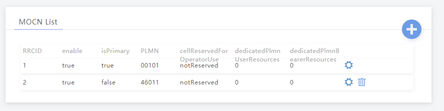
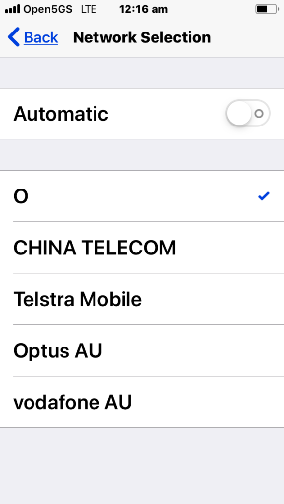
MOCN is one of those great concepts I’d not really come across,
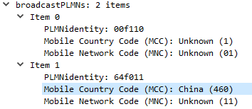
Multi-tenancy on the RAN side of the network, allowing an eNB to broadcast multiple PLMN IDs (MCC/MNC) in the System Information Block (SIB).
It allows site sharing not just on the tower itself, but site sharing on the RAN side, allowing customers of MNO A to see themselves connected to MNO A, and customers from MNO B see themselves as connected to MNO B, but they’re both connected to the same RAN hardware.
Setup in my lab was a breeze; your RAN hardware will probably be different.
In terms of signaling it’s a standard S1AP Setup Request except with multiple broadcast PLMN keys:
I’ve been working for some time on open source mobile network cores, and one feature that has been a real struggle for a lot of people (Myself included) is getting VoLTE / IMS working.
Here’s some of the issues I’ve faced, and the lessons I learned along the way,
Sadly on most UEs / handsets, there’s no “Make VoLTE work now” switch, you’ve got a satisfy a bunch of dependencies in the OS before the baseband will start sending SIP anywhere.
Get the right Hardware
Your eNB must support additional bearers (dedicated bearers I’ve managed to get away without in my testing) so the device can setup an APN for the IMS traffic.
Sadly at the moment this rules our Software Defined eNodeBs, like srsENB.
ISIM – When you thought you understood USIMs – Guess again
According to the 3GPP IMS docs, an ISIM (IMS SIM) is not a requirement for IMS to work.
However in my testing I found Android didn’t have the option to enable VoLTE unless an ISIM was present the first time.
In a weird quirk I found once I’d inserted an ISIM and connected to the VoLTE network, I could put a USIM in the UE and also connect to the VoLTE network.
Obviously the parameters you can set on the USIM, such as Domain, IMPU, IMPI & AD, are kind of “guessed” but the AKAv1-MD5 algorithm does run.
Getting the APN Config Right
There’s a lot of things you’ll need to have correct on your UE before it’ll even start to think about sending SIP messaging.
I was using commercial UE (Samsung handsets) without engineering firmware so I had very limited info on what’s going on “under the hood”. There’s no “Make VoLTE do” tickbox, there’s VoLTE enable, but that won’t do anything by default.
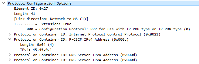
If your P-GW doesn’t know the IP of your P-CSCF, it’s not going to be able to respond to it in the Protocol Configuration Options (PCO) request sent by the UE with that nice new bearer for IMS we just setup.
There’s no way around Mutual Authentication
Coming from a voice background, and pretty much having RFC 3261 tattooed on my brain, when I finally got the SIP REGISTER request sent to the Proxy CSCF I knocked something up in Kamailio to send back a 200 OK, thinking that’d be the end of it.
For any other SIP endpoint this would have been fine, but IMS Clients, nope.
Reading the specs drove home the same lesson anyone attempting to setup their own LTE network quickly learns – Mutual authentication means both the network and the UE need to verify each other, while I (as the network) can say the UE is OK, the UE needs to check I’m on the level.
I saw my 401 response go back to the UE and then no response. Nada.
This led to my next lesson…
There’s no way around IPsec
According to the 3GPP docs, support for IPsec is optional, but I found this not to be the case on the handsets I’ve tested.
After sending back my 401 response the UE looks for the IPsec info in the 401 response, then tries to setup an IPsec SA and sends ESP packets back to the P-CSCF address.
Even with my valid AKAv1-MD5 auth, I found my UE wasn’t responding until I added IPsec support on the P-CSCF, hence why I couldn’t see the second REGISTER with the Authentication Info.
After setting up IPsec support, I finally saw the UE’s REGISTER with the AKAv1-MD5 authentication, and was able to send a 200 OK.
For my LTE lab I got myself a BaiCells Neutrino, it operates on Band 3 (FDD ~1800Mhz) with only 24dBm of output power max and PoE powered it works well in a lab environment without needing -48vDC supply, BBUs, DUs feeders and antennas.
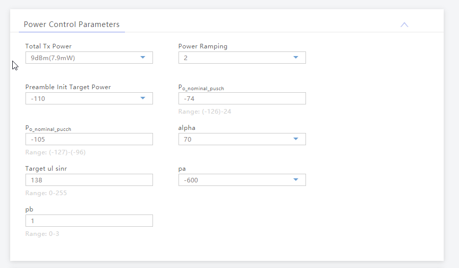
Setup can be done via TR-069 or via BaiCells management server, for smaller setups the web UI makes setup pretty easy,
Logging in with admin/admin to the web interface:
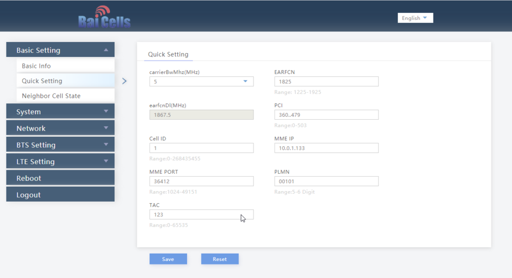
We’ll select Quick Settings, and load in our MME IP address, PLMN (MCC & MNC), Tracking Area Code, Cell ID and Absolute Radio Frequency No.
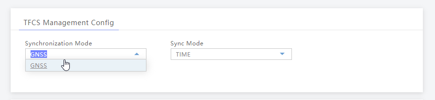
Once that’s done we’ll set our Sync settings to use GPS / GNSS (I’ve attached an external GPS Antenna purchased cheaply online).
Finally we’ll set the power levels, my RF blocking setup is quite small so I don’t want excess power messing around with it, so I’ve dialed the power right back:
And that’s it, it’ll now connect to my MME on 10.0.1.133 port 36412 on SCTP.
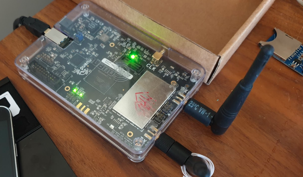
The team at Software Radio Systems in Ireland have been working on an open source LTE stack for some time, to be used with software defined radio (SDR) hardware like the USRP, BladeRF and LimeSDR.
They’ve released SRSUE and SRSENB their open source EUTRAN UE and eNodeB, which allow your SDR hardware to function as a LTE UE and connect to a commercial eNB like a standard UE while getting all the juicy logs and debug info, or as a LTE eNB and have commercial UEs connect to a network you’re running, all on COTS hardware.
The eNB supports S1AP to connect to a 3GPP compliant EPC, like Open5Gs, but also comes bundled with a barebones EPC for testing.
The UE allows you to do performance testing and gather packet captures on the MAC & PHY layers, something you can’t do on a commericial UE. It also supports software-USIMs (IMSI / K / OP variables stored in a text file) or physical USIMs using a card reader.
I’ve got a draw full of SDR hardware, from the first RTL-SDR dongle I got years ago, to a few HackRFs, a LimeSDR up to the BladeRF x40.
Really cool software to have a play with, I’ve been using SRSUE to get a better understanding of the lower layers of the Uu interface.
Installation
After mucking around trying to satisfy all the dependencies from source I found everything I needed could be found in Debian packages from the repos of the maintainers.
To begin with we need to install the BladeRF drivers and SopySDR modules to abstract it to UHD:
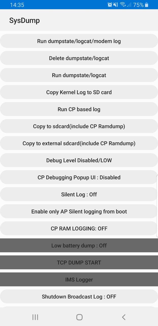
Samsung handsets have a feature built in to allow debugging from the handset, called Sysdump.
Entering *#9900# from the Dialing Screen will bring up the Sysdump App, from here you can dump logs from the device, and run a variety of debugging procedures.
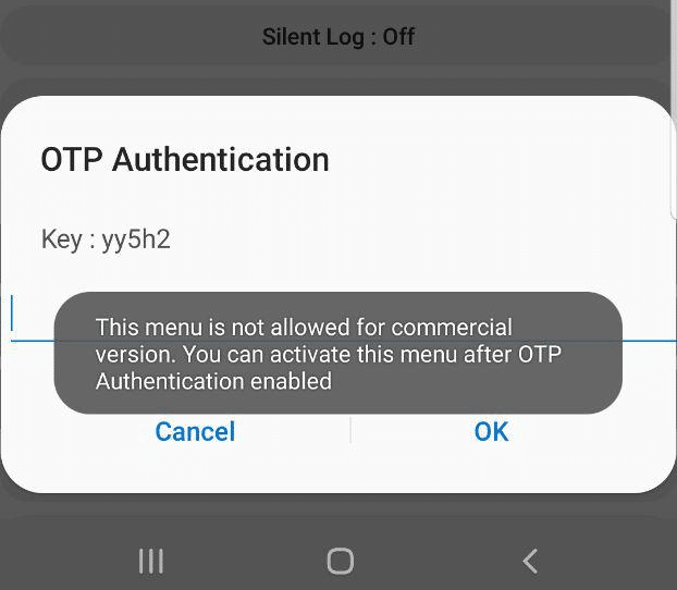
But for private LTE operators, the two most interesting options are by far the TCPDUMP START option and IMS Logger, but both are grayed out.
Tapping on them asks for a one-time password and has a challenge key.
These options are not available in the commercial version of the OS and need to be unlocked with a one time key generated by a tool Samsung for unlocking engineering firmware on handsets.
Luckily this authentication happens client side, which means we can work out the password it’s expecting.
Once you’ve entered the code and successfully unlocked the IMS Debugging tool there’s a few really cool features in the hamburger menu in the top right.
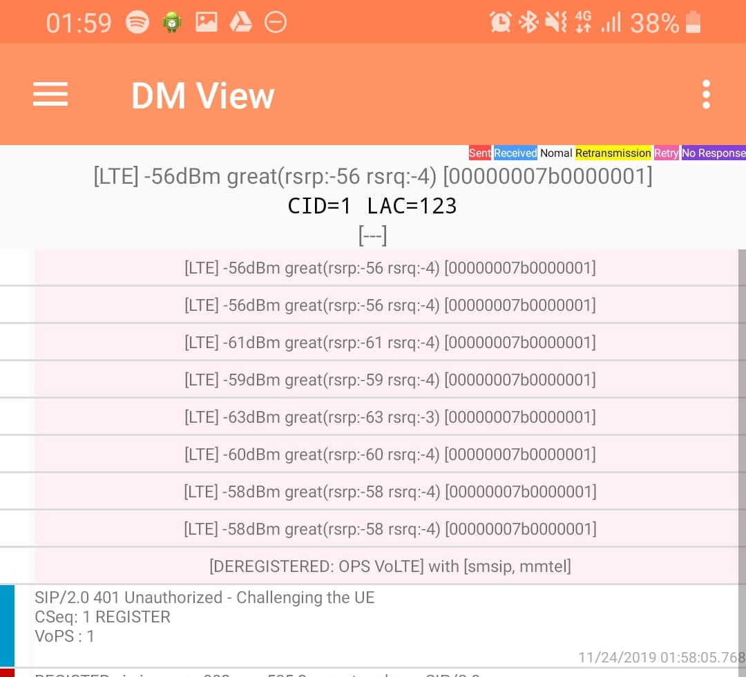
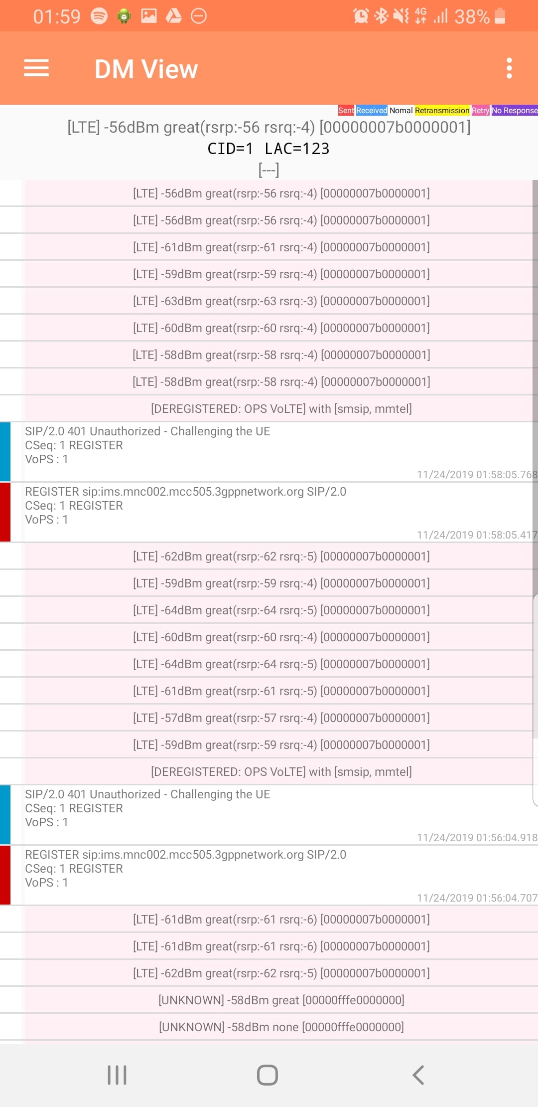
DM View
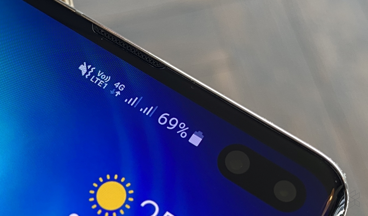
This shows the SIP / IMS Messaging and the current signal strength parameters (used to determine which RAN type to use (Ie falling back from VoLTE to UMTS / Circuit Switched when the LTE signal strength drops).
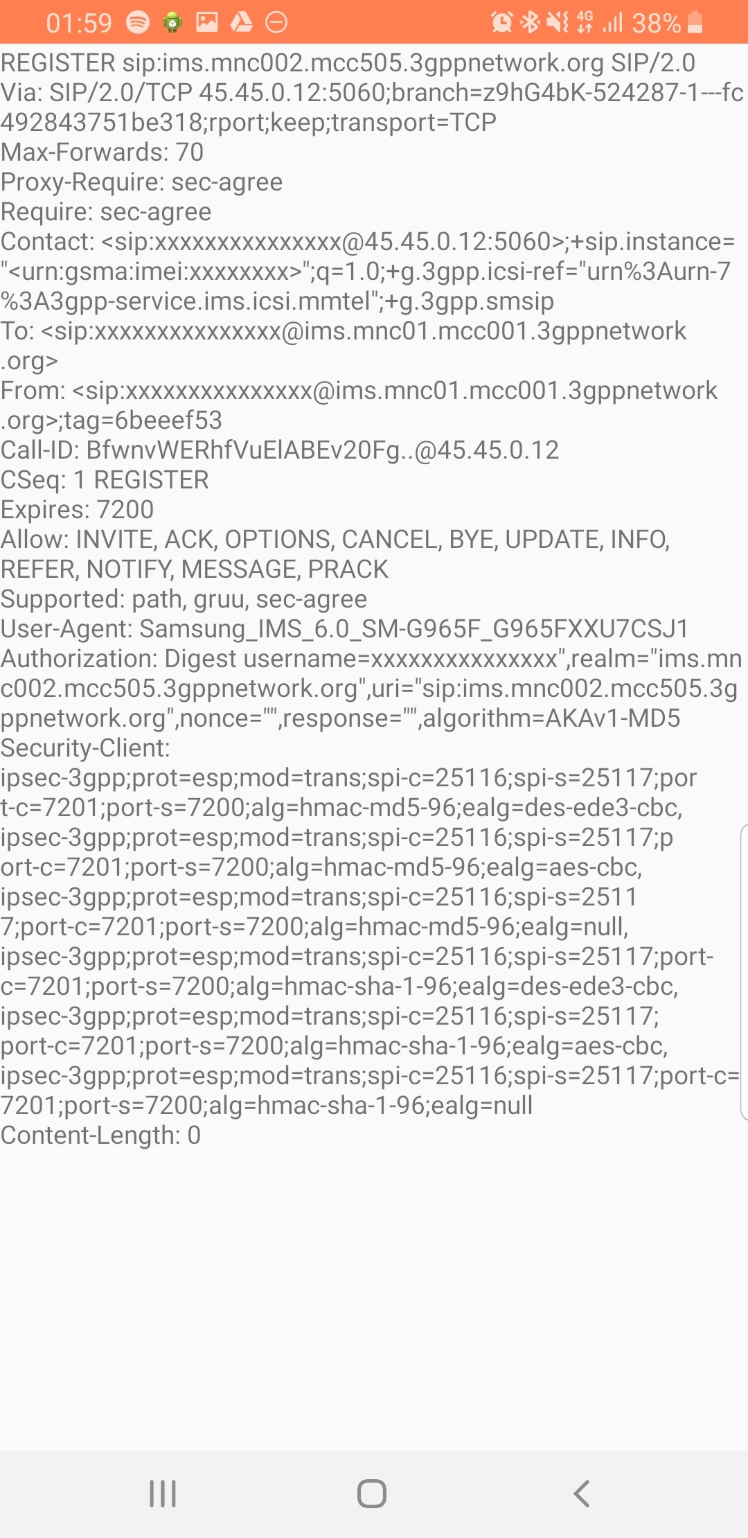
Tapping on the SIP messages expands them and allows you to see the contents of the SIP messages.
Viewing SIP Messaging directly from the handset
Interesting the actual nitty-gritty parameters in the SIP headers are missing, replaced with X for anything “private” or identifiable.
Luckily all this info can be found in the Pcap.
The DM View is great for getting a quick look at what’s going on, on the mobile device itself, without needing a PC.
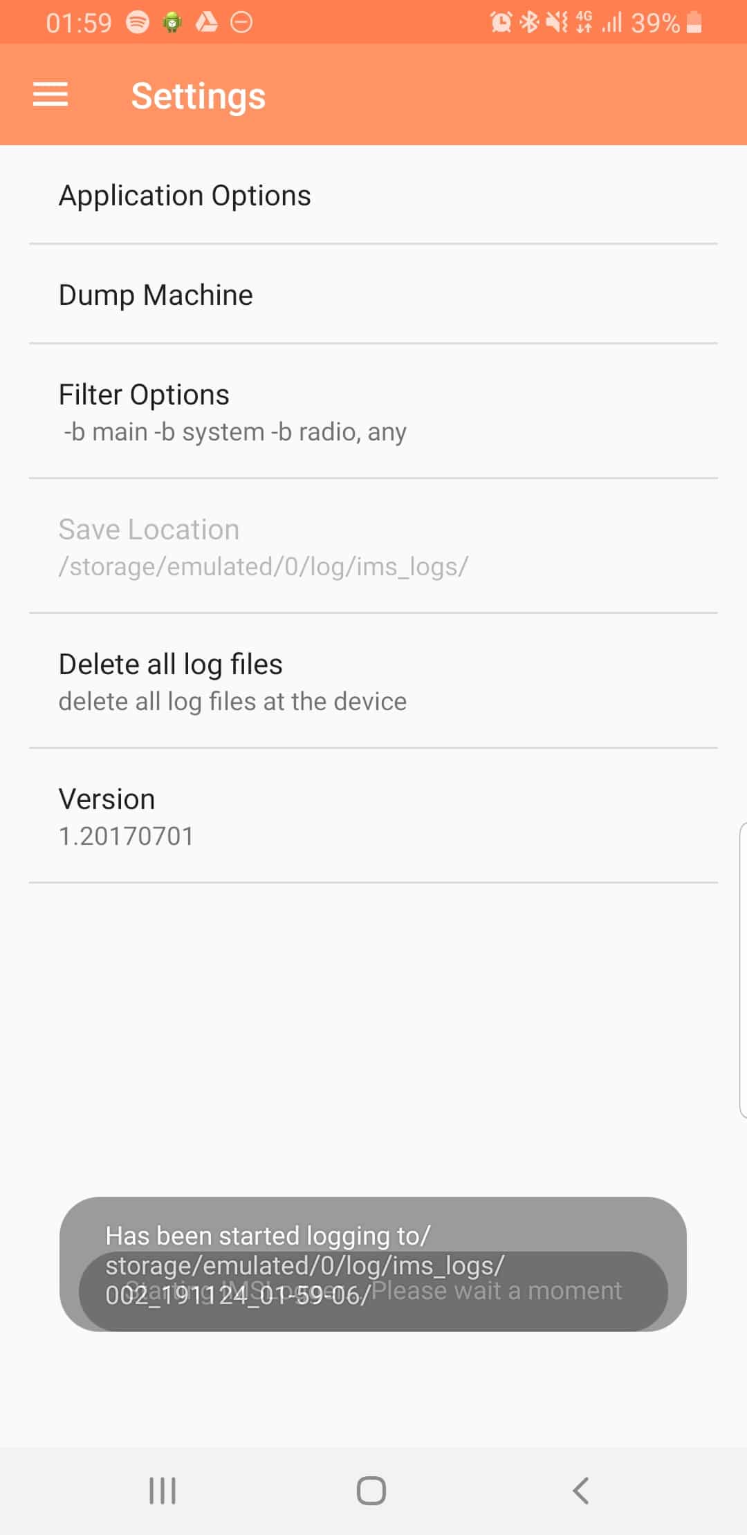
Logging
The real power comes in the logging functions,
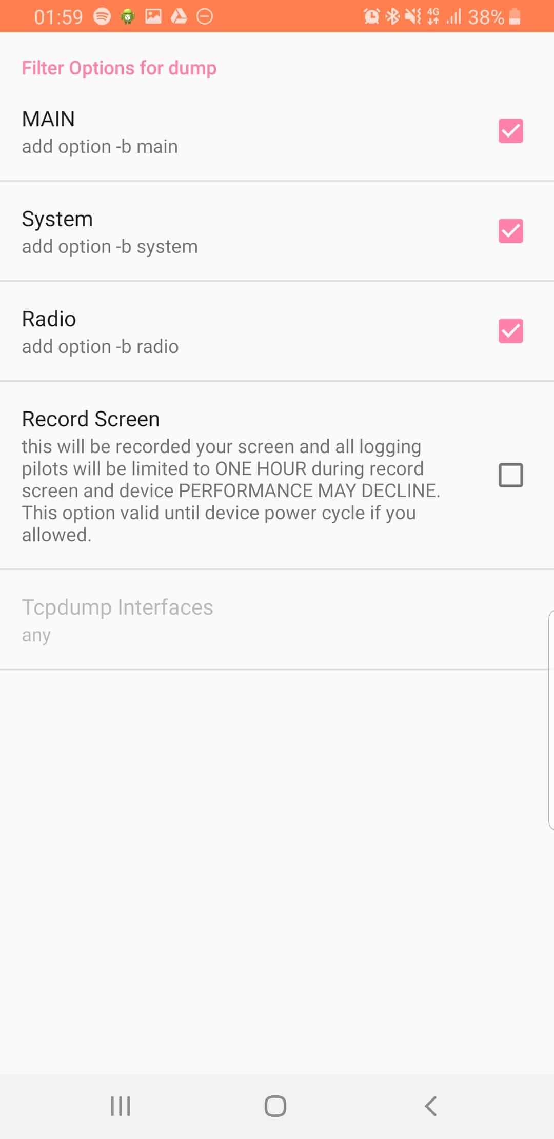
There’s a lot of logging options, including screen recording, TCPdump (as in Packet Captures) and Syslog logging.
From the hamburger menu we can select the logging parameters we want to change.
From the Filter Options menu we can set what info we’re going to log,
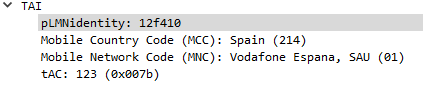
The PLMN Identifier is used to identify the radio networks in use, it’s made up of the MCC – Mobile Country Code and MNC – Mobile Network Code.
But sadly it’s not as simple as just concatenating MCC and MNC like in the IMSI, there’s a bit more to it.
In the example above the Tracking Area Identity includes the PLMN Identity, and Wireshark has been kind enough to split it out into MCC and MNC, but how does it get that from the value 12f410?
This one took me longer to work out than I’d like to admit, and saw me looking through the GSM spec, but here goes:
PLMN Contents: Mobile Country Code (MCC) followed by the Mobile Network Code (MNC). Coding: according to TS GSM 04.08 [14].
If storage for fewer than the maximum possible number n is required, the excess bytes shall be set to ‘FF’. For instance, using 246 for the MCC and 81 for the MNC and if this is the first and only PLMN, the contents reads as follows: Bytes 1-3: ’42’ ‘F6′ ’18’ Bytes 4-6: ‘FF’ ‘FF’ ‘FF’ etc.
TS GSM 04.08 [14].
Making sense to you now? Me neither.
Here’s the Python code I wrote to encode MCC and MNCs to PLMN Identifiers and to decode PLMN into MCC and MNC, and then we’ll talk about what’s happening:
In the above example I take MCC 505 (Australia) and MCC 93 and generate the PLMN ID 05f539.
The first step in decoding is to take the first two bits (in our case 05 and reverse them – 50, then we take the third and fourth bits (f5) and reverse them too, and strip the letter f, now we have just 5. We join that with what we had earlier and there’s our MCC – 505.
Next we get our MNC, for this we take bytes 5 & 6 (39) and reverse them, and there’s our MNC – 93.
Together we’ve got MCC 505 and MNC 93.
The one answer I’m still looking for; why not just encode 50593? What is gained by encoding it as 05f539?
LTE has great concepts like NAS that abstract the actual transport layers, so the NAS packet is generated by the UE and then read by the MME.
One thing that’s a real headache about private LTE is the authentication side of things. You’ll probably bash your head against a SIM programmer for some time.
As your probably know when connecting to a network, the UE shares it’s IMSI / TIMSI with the network, and the MME requests authentication information from the HSS using the Authentication Information Request over Diameter.
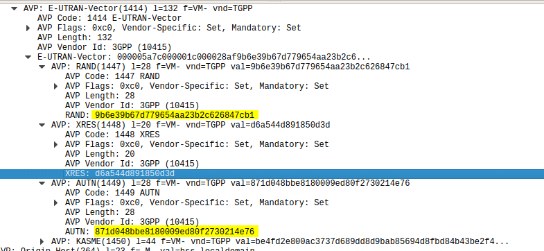
The HSS then returns a random value (RAND), expected result (XRES), authentication token (AUTN) and a KASME for generating further keys,
The RAND and AUTN values are sent to the UE, the USIM in the UE calculates the RES (result) and sends it back to the MME. If the RES value received by the MME is equal to the expected RES (XRES) then the subscriber is mutually authenticated.
Using this tool I was able to plug a USIM into my USIM reader, using the Diameter client built into PyHSS I was able to ask for Authentication vectors for a UE using the Authentication Information Request to the HSS and was sent back the Authentication Information Answer containing the RAND and AUTN values, as well as the XRES value.
Diameter – Authentication Information Response showing E-UTRAN Vectors
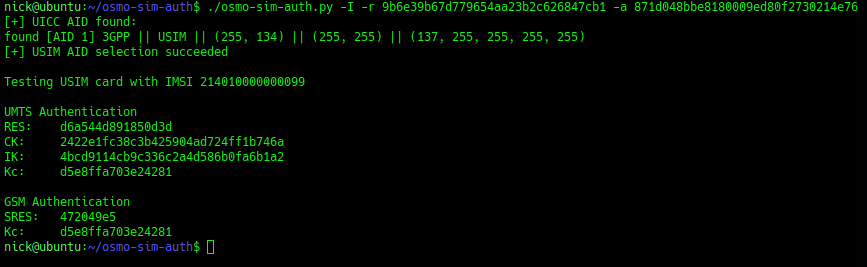
Then I used the osmo-sim-auth app to query the RES and RAND values against the USIM.
The RES I got back matched the XRES, meaning the HSS and the USIM are in sync (SQNs match) and they mutually authenticated.
I thought I’d expand a little on how the Crypto side of things works in LTE & NR (also known as 4G & 5G).
Authentication primarily happens in two places, one at each end of the network, the Home Subscriber Server and in the USIM card. Let’s take a look at each of them.
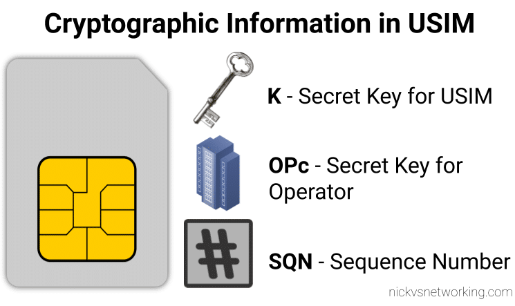
On the USIM
On the USIM we’ve got two values that are entered in when the USIM is provisioned, the K key – Our secret key, and an OPc key (operator key).
These two keys are the basis of all the cryptography that goes on, so should never be divulged.
The only other place to have these two keys in the HSS, which associates each K key and OPc key combination with an IMSI.
The USIM also stores the SQN a sequence number, this is used to prevent replay attacks and is incremented after each authentication challenge, starting at 1 for the first authentication challenge and counting up from there.
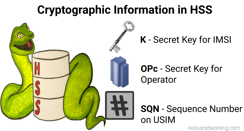
On the HSS
On the HSS we have the K key (Secret key), OPc key (Operator key) and SQN (Sequence Number) for each IMSI on our network.
Each time a IMSI authenticates itself we increment the SQN, so the value of the SQN on the HSS and on the USIM should (almost) always match.
Authentication Options
Let’s imagine we’re designing the authentication between the USIM and the Network; let’s look at some options for how we can authenticate everyone and why we use the process we use.
Failed Option 1 – Passwords in the Clear
The HSS could ask the USIM to send it’s K and OPc values, compare them to what the HSS has in place and then either accept or reject the USIM depending on if they match.
The obvious problem with this that to send this information we broadcast our supposedly secret K and OPc keys over the air, so anyone listening would get our secret values, and they’re not so secret anymore.
This is why we don’t use this method.
Failed Option 2 – Basic Crypto
So we’ve seen that sending our keys publicly, is out of the question.
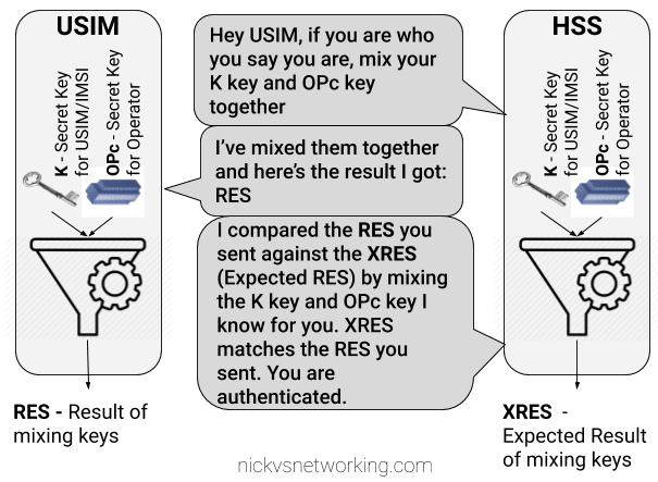
The HSS could ask the USIM to mix it’s K key and OPc key in such a way that only someone with both keys could unmix them.
This is done with some cryptographic black magic, all you need to know is it’s a one way function you enter in values and you get the same result every time with the same input, but you can’t work out the input from the result.
The HSS could then get the USIM to send back the result of mixing up both keys, mix the two keys it knows and compare them.
The HSS mixes the two keys itself, and get’s it’s own result called XRES (Expected Result). If the RES (result) of mixing up the keys by the USIM is matches the result when the HSS mixes the keys in the same way (XRES (Expected Result)), the user is authenticated.
The result of mixing the keys by the USIM is called RES (Result), while the result of the HSS mixing the keys is called XRES (Expected Result).
This is abetter solution but has some limitations, because our special mixing of keys gets the same RES each time we put in our OPc and K keys each time a subscriber authenticates to the network the RES (result) of mixing the keys is going to be the same.
This is vulnerable to replay attacks. An attacker don’t need to know the two secret keys (K & OPc) that went into creating the RES (resulting output) , the attacker would just need to know the result of RES, which is sent over the air for anyone to hear. If the attacker sends the same RES they could still authenticate.
This is why we don’t use this method.
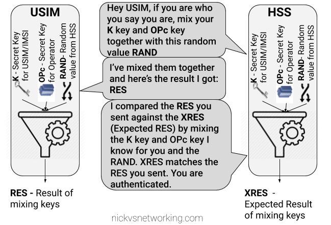
Failed Option 3 – Mix keys & add Random
To prevent these replay attacks we add an element of randomness, so the HSS generates a random string of garbage called RAND, and sends it to the USIM.
The USIM then mixes RAND (the random string) the K key and OPc key and sends back the RES (Result).
Because we introduced a RAND value, every time the RAND is different the RES is different. This prevents against the replay attacks we were vulnerable to in our last example.
If the result the USIM calculated with the K key, OPc key and random data is the same as the USIM calculated with the same K key, OPc key and same random data, the user is authenticated.
While an attacker could reply with the same RES, the random data (RAND) will change each time the user authenticates, meaning that response will be invalid.
While an attacker could reply with the same RES, the random data (RAND) will change each time the user authenticates, meaning that response will be invalid.
The problem here is now the network has authenticated the USIM, the USIM hasn’t actually verified it’s talking to the real network.
This is why we don’t use this method.
GSM authentication worked like this, but in a GSM network you could setup your HLR (The GSM version of a HSS) to allow in every subscriber regardless of what the value of RES they sent back was, meaning it didn’t look at the keys at all, this meant attackers could setup fake base stations to capture users.
Option 4 – Mutual Authentication (Real World*)
So from the previous options we’ve learned:
Our network needs to authenticate our subscribers, in a way that can’t be spoofed / replayed so we know who to bill & where to route traffic.
Our subscribers need to authenticate the network so they know they can trust it to carry their traffic.
So our USIM needs to authenticate the network, in the same way the network authenticates the USIM.
To do this we introduce a new key for network authentication, called AUTN.
The AUTN key is generated by the HSS by mixing the secret keys and RAND values together, but in a different way to how we mix the keys to get RES. (Otherwise we’d get the same key).
This AUTN key is sent to the USIM along with the RAND value. The USIM runs the same mixing on it’s private keys and RAND the HSS did to generate the AUTN , except this is the USIM generated – An Expected AUTN key (XAUTN). The USIM compares XAUTN and AUTN to make sure they match. If they do, the USIM then knows the network knows their secret keys.
The USIM then does the same mixing it did in the previous option to generate the RES key and send it back.
The network has now authenticated the subscriber (HSS has authenticated the USIM via RES key) and the subscriber has authenticated the USIM (USIM authenticates HSS via AUTN key).
*This is a slightly simplified version of how EUTRAN / LTE authentication works between the HSS and the USIM – In reality there are a few extra values, such as SQN to take into consideration and the USIM talks to to the MME not the HSS directly.
I’ll do a follow up post covering the more nitty-gritty elements, AMF and SQN fields, OP vs OPc keys, SQN Resync, how this information is transfered in the Authentication Information Answer and how KASME keys are used / distributed.
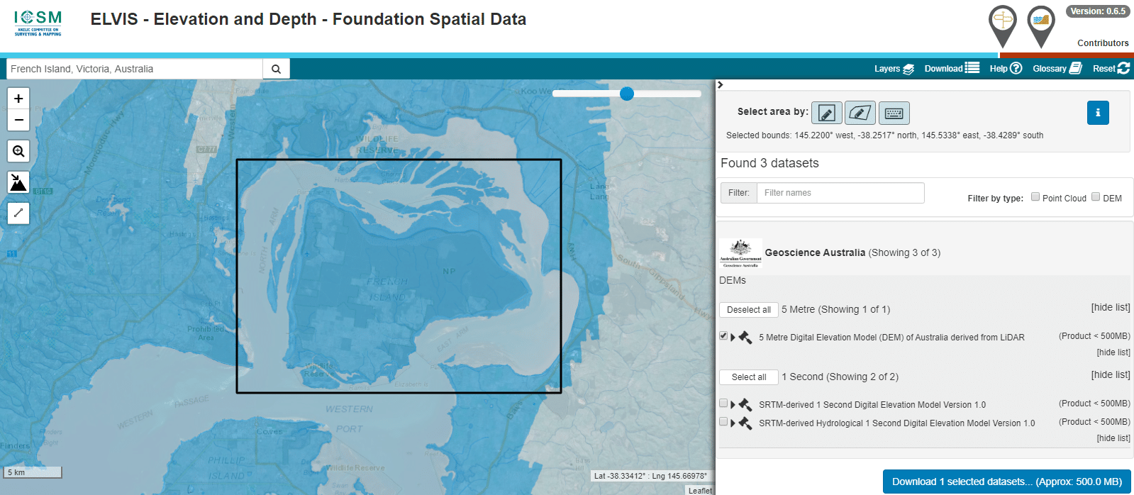
The Australian Government publishes elevation data online that’s freely available for anyone to use. There’s a catch – If you’re using Forsk Atoll, it won’t import without a fair bit of monkeying around with the data…
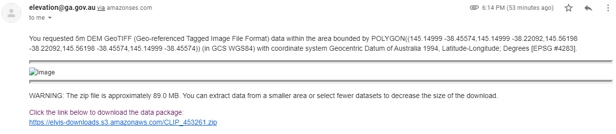
You draw around the area you want to download, enter your email address and you’re linked to a download of the dataset you’ve selected.
So now we download the data from the link, unzip it and we’re provided with a .tiff image with the elevation data in the pixel colour and geocoded with the positional information.
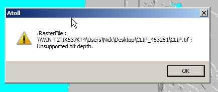
Problem is, this won’t import into Atoll – Unsupported depth.
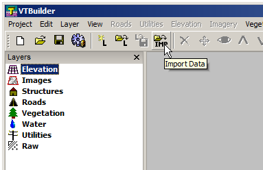
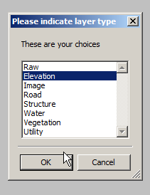
I fired it up, and imported the elevation tiff file we’d downloaded.
Selected “Elevation” waited a few seconds and presto!
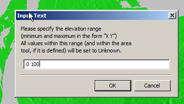
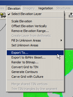
We can export from here in the PNG 16 bit grayscale format Atoll takes, but there’s a catch, negative elevation values and blank data will show up as giant spikes which will totally mess with your propagation modeling.
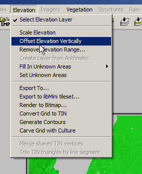
So I found an option to remove elevation data from a set range, but it won’t deal with negative values…
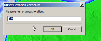
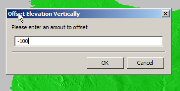
So I found another option in the elevation menu to offset elevation vertically, I added 100 ft (It’s all in ft for some reason) to everything which meant my elevation data that was previously negative was now just under 100.
So if an area was -1ft before it was now 99ft.
Now I was able to use the remove range for anything from 0 100 ft (previously sea level)
Now my map only shows data above sea level
Now I offset the elevation vertically again and remove 100ft so we get back to real values
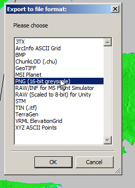
Now I was able to export the elevation data from the Elevation -> Export to menu
Atoll seems to like PNG 16 bit greyscale so that’s what we’ll feed it.
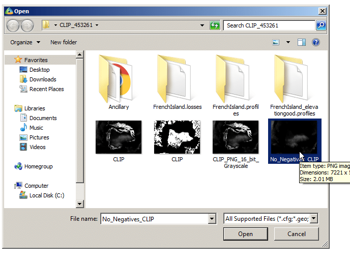
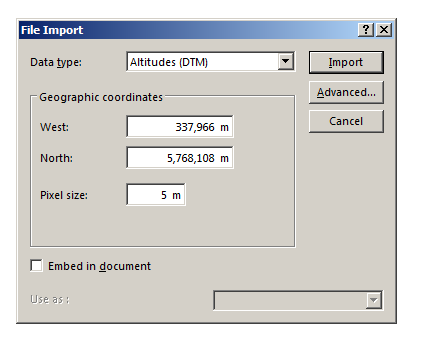
In Atoll we’ll select File -> Import and open the PNG we just generated.
Data type will be Altitude, Pixel size is 5m (as denoted in email / dataset metadata).
Next question is offset, which took me a while to work out…
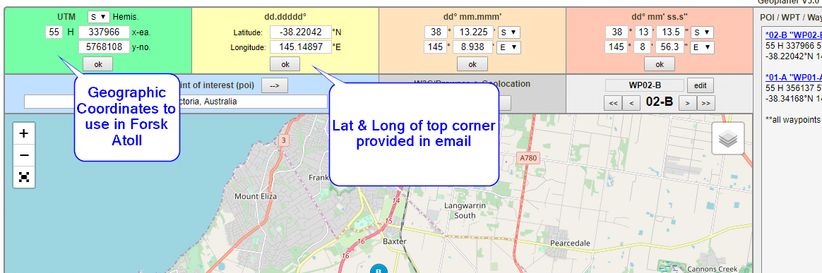
The email has the Lat & Long but Atoll deals in WGS co-ordinates,
Luckily the GeoPlanner website allows you to enter the lat & long of the top corner and get the equivalent West and North values for the UTM dataum.
Enter these values as your coordinates and you’re sorted.
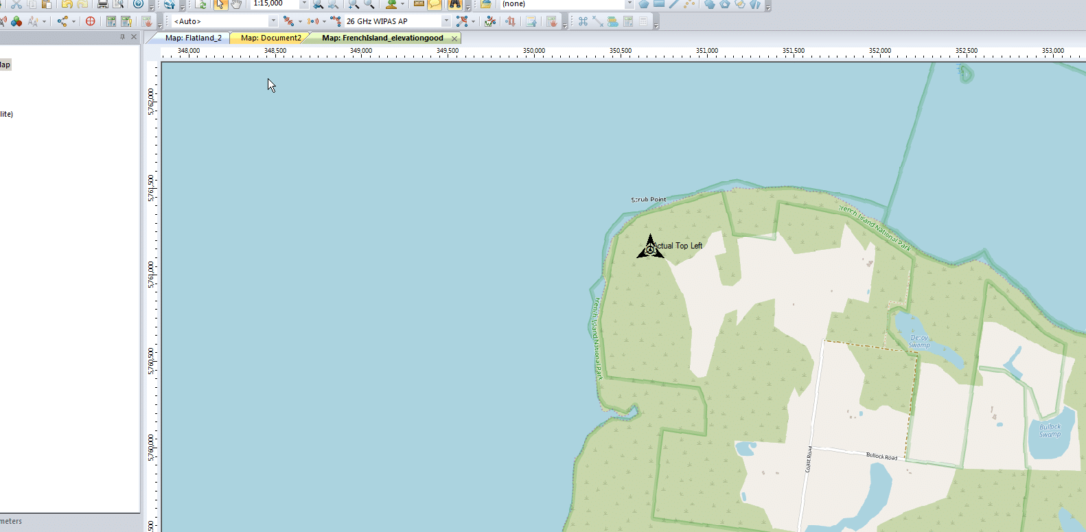
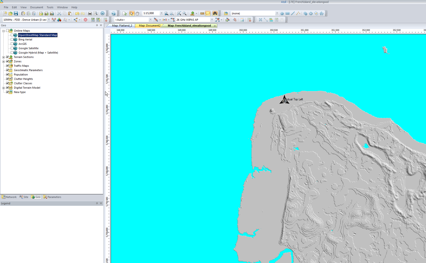
I can even able a Map layer and confirm it lines up:
Let’s take a look at GTP, the workhorse of mobile user plane packet data.
This post covers all generations of mobile data (2.5 -> 5G), so I’m using generic terms.
GSM, UMTS, LTE & NR all have one protocol in common – GTP – The GPRS Tunneling Protocol.
So why do every generation of mobile data networks from GSM/GPRS in 2000, to 5G NR Standalone in 2020, rely on this one protocol for transporting user data?
So Why GTP?
GTP – the GPRS Tunnelling Protocol, is what encapsulates and tunnels IP packets from the internet / packet data network, to and from the User.
So why encapsulate the packets? What if the Base Station had access to the internet and routed the traffic to the users?
Let’s say we did that, we’d have to have large pools of IP addresses available at each Base Station and when a user connected they’d be assigned an IP Address and traffic for these users would be routed to the Base Station which would forward it onto the user.
This would work well until a user moves from one Base Station to another, when they’d have to get a new IP Address allocated.
TCP/IP was never designed to be mobile, an IP address only exists in a single location.
Breaking out traffic directly from a base station would have other issues, such as no easy way to enforce QoS or traffic policies, meter usage, etc.
How to fix IP’s lack of mobility? GTP.
GTP addressed the mobility issue by having a single fixed point the IP Address is assigned to (In GSM/GRPS/UMTS this is the Gateway GPRS Support Node, in LTE this is the P-GW and in 5G-SA this is the UPF), which encapsulates IP traffic to/from a mobile user into GTP Packet.
You can think of GTP like GRE or any of the other common encapsulation protocols, wrapping up the IP packets into a GTP packet which we can rerouted to different Base Stations as the users move from being served by one Base Station to another.
This easy redirecting / rerouting of user traffic is why GTP is used for NR (5G), LTE (4G), UMTS (3G) & GPRS (2.5G) architectures.
GTP Packets
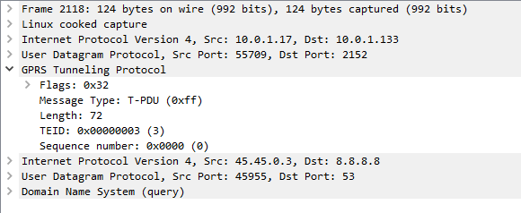
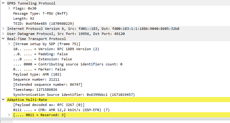
When looking at a GTP packet of user data you’d be forgiven for thinking nothing much goes on,
Example GTP packet containing a DNS query
Like in most tunneling / encapsulation protocols we’ve got the original network / protocol stack of IPv4 and UDP, and a payload of a GTP packet.
The packet itself is pretty bare bones, there’s flags, denoting a few basics like version number, the message type (T-PDU), the length of the GTP packet and it’s payload (used for delineating the end of the payload), a sequence number an a Tunnel Endpoint Identifier (TEID).
In the payload, we can see the network / protocol stack and application layer of the contents of the GTP packet.
From a mobility standpoint, the beauty of GTP is that it takes IP packets and puts them into a media stream of sorts, with out of band signalling, this means we can change the parameters of our GTP stream easily without touching the encapsulated IP Packet.
When a UE moves from one base station to another, all that has to happen is the destination the GTP packets are sent to is changed from the old base station to the new base station. This is signalled using GTP-C in GPRS/UMTS, GTPv2-C in LTE and HTTP in 5G-SA.
Traffic to and from the UE would look the same as the screenshot above, the only difference would be the first IPv4 address would be different, but the IPv4 address in the GTP tunnel would be the same.
I started working on a private LTE project a while ago; RAN hardware (eNodeBs) were on the way, down to a shortlist of a few EPC platforms, but I still needed USIMs before anyone was connecting to the network.
So why are custom USIMs a requirement? Can’t you just use any old USIM/SIMs?
For roaming to work between carriers they’ve got to have their HSS / DRA connecting to the DRA or HSS of other carriers, to allow roaming subscribers to access the network, otherwise they too would fall foul of the mutual network authentication and the USIM wouldn’t connect to the network.
The first USIMs I purchased online through a popular online marketplace with a focus on connecting you to Chinese manufacturers. They listed a package of USIMS, a USB reader/writer that supported all the standard USIM form factors and the software to program it, which I purchased.
The USIMs worked fairly well – They are programmable via a card reader and software that, although poorly translated/documented, worked fairly well.
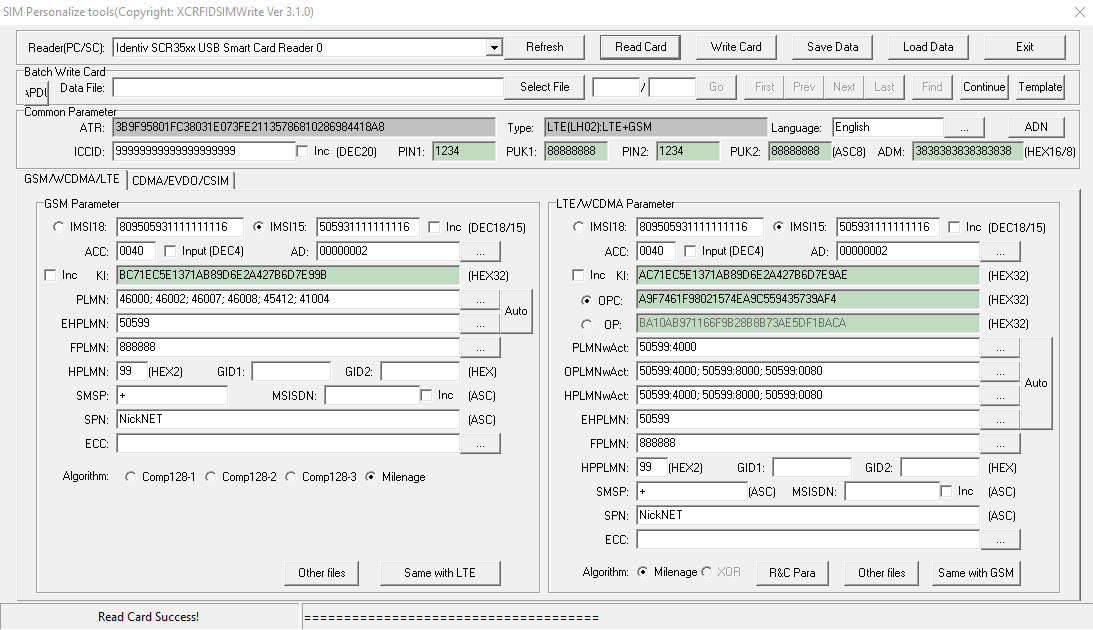
USIM Programming Interface
K and OP/OPc values could be written to the card but not read, while the other values could be read and written from the software, the software also has the ability to sequentially program the USIMs to make bulk operations easier. The pricing worked out about $8 USD per USIM, which although expensive for the quantity and programmable element is pretty reasonable.
Every now and then the Crypto values for some reason or another wouldn’t get updated, which is exactly as irritating as it sounds.
Pretty quickly into the build I learned the USIMs didn’t include an ISIM service on the card, ISIM being the service that runs on the UCCID responsible for IMS / VoLTE authentication.
Again I went looking and reached out to a few manufacturers of USIMs.
The big vendors, Gemalto, Kona, etc, weren’t interested in providing USIMs in quantities less than 100,000 and their USIMs came from the factory pre-programmed, meaning the values could only be changed through remote SIM provisioning, a form of black magic.
In the end I reached out to an OEM manufacturer from China who provided programmable USIM / ISIMs for less than I was paying on the online marketplace and at any quantity I wanted with custom printing options, allocated ICCIDs, etc.
The non-programmable USIMs worked out less than $0.40 USD each in larger quantities, and programmable USIM/ISIMs for about $5 USD.
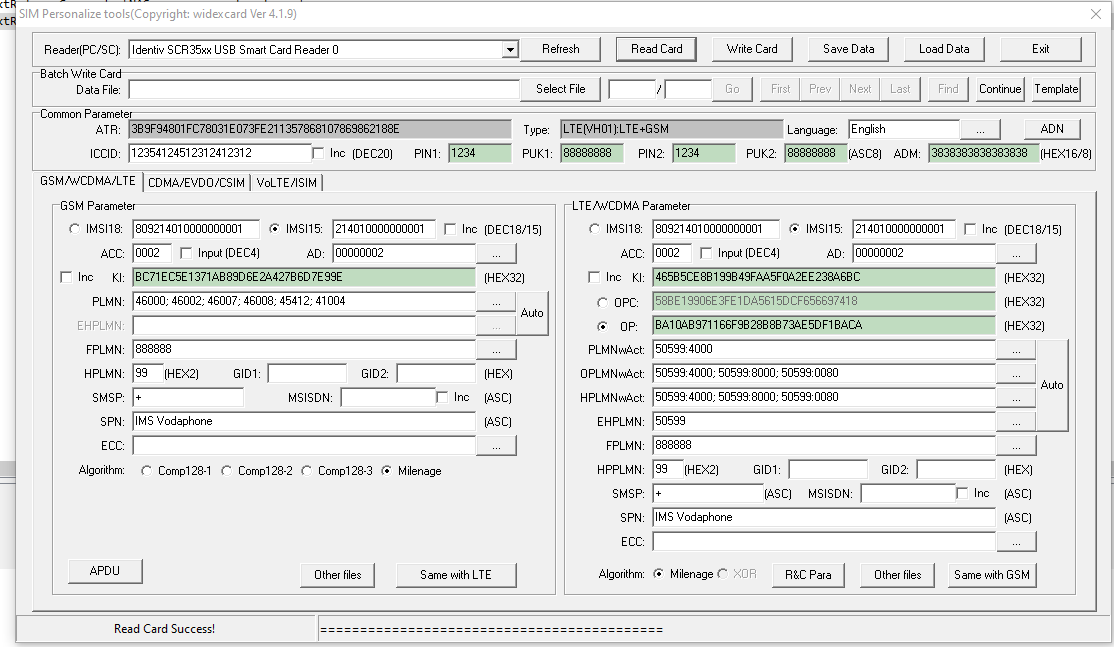
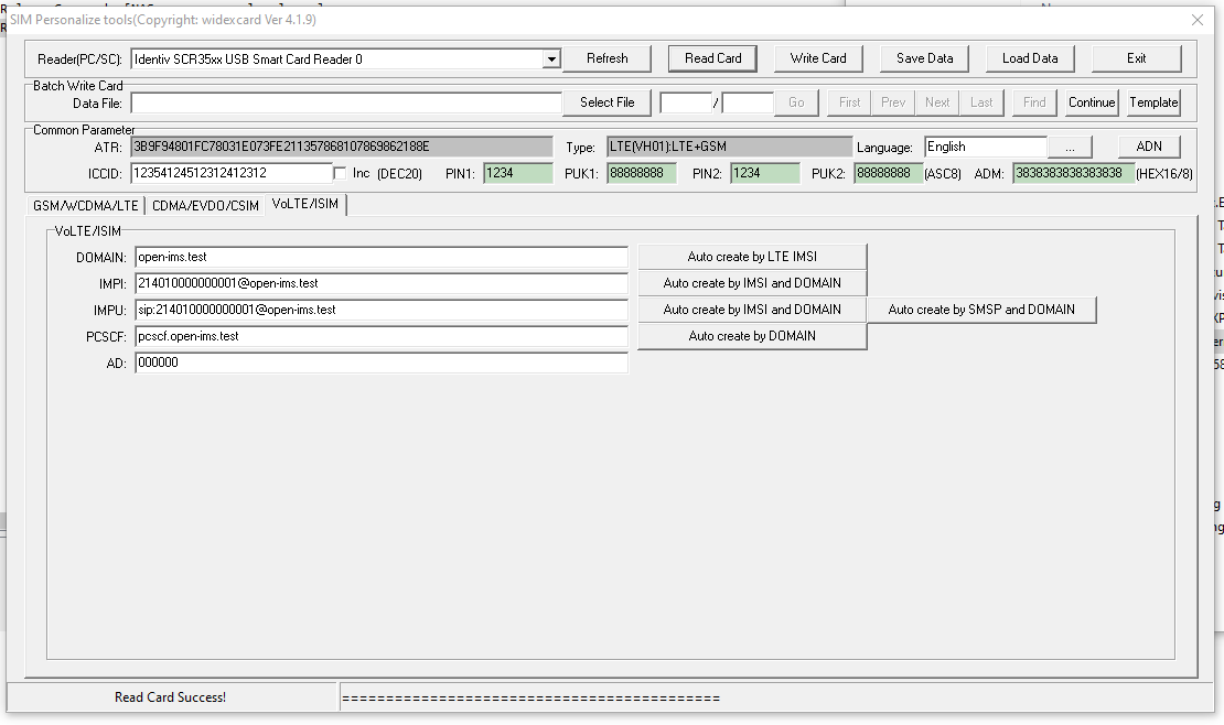
The software was almost identical except for the additional tab for ISIM operations.
USIM / ISIM programmingISIM parameters
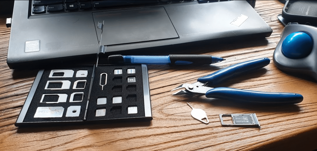
Smart Card Readers
In theory this software and these USIMs could be programmed by any smart card reader.
In practice, the fact that the ISO standard smart card is the same size as a credit card, means most smart card readers won’t fit the bill.
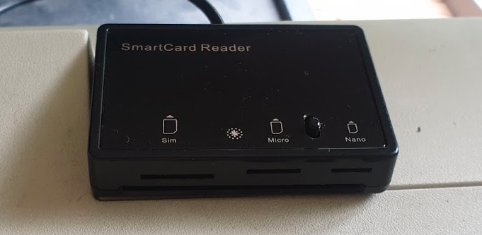
I tried a few smart card readers, from the one built into my Thinkpad, to a Bluedrive II from one of the USIM vendors, in the end the MCR3516 Smart Card Reader which reads 4FF USIMs (Standard ISO size smart card, full size SIM, Micro SIM and Nano SIM form factors, which saved on so much mucking about with form factor adapters etc.
4FF Smart Card Reader for programming SIM/USIM/ISIM
Future Projects
I’ve got some very calls “Multi Operator Neutral Host” (MoNEH) USIMs from the guys at Telet Research I’m looking forward to playing with,
eSIMs are on my to-do list too, and the supporting infrastructure, as well as Over the Air updating of USIMs.
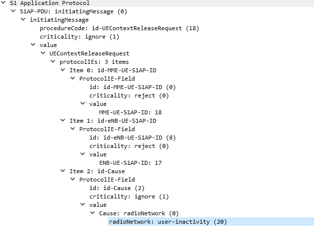
In order to keep radio resources free, if a UE doesn’t send or receive data for a predefined threshold, it’ll detach from the network and call back to Idle mode.
If the UE has data to send to the network, the UE will re-attach to the network, whereas if the network has data to send to the UE, it’ll Page the UE in the tracking area it’s currently in, the UE is always listening for it’s identifier (s-TMSI) on the paging channel, and if it hears it’s identifier called, the UE will re-attach.
I’ve also attached a PCAP file of the packet flow between the eNB and the MME.
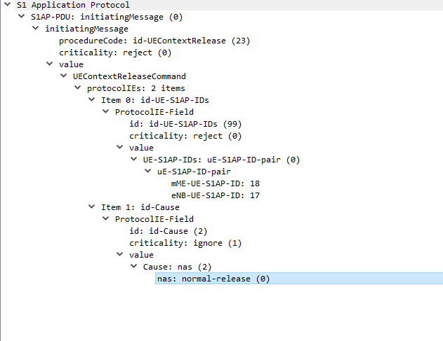
The next packet is sent from the MME back to the eNB confirming UE is releasing from the network.
UEContextReleaseCommand
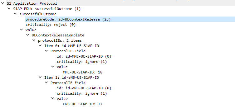
UEContextReleaseComplete
Finally after the UE has released it’s radio resources the eNB sends a UEContextReleaseComplete so the MME knows the UE is now in Idle state and will need to be paged.
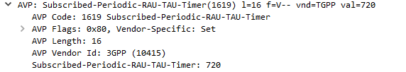
Recently we saw Open5Gs’s Update Location Answer response putting the Subscribed-Periodic-RAU-TAU-Timer AVP in the top level and not in the AVP Code 1400 (APN Configuration) Diameter payload from the HSS to the MME.
But what exactly does the Subscribed-Periodic-RAU-TAU-Timer AVP in the Update Location Answer response do?
Folks familiar with EUTRAN might recognise TAU as Tracking Area Update, while RAU is Routing Area Update in GERAN/UTRAN (UMTS).
Periodic tracking area updating is used to periodically notify the availability of the UE to the network. The procedure is controlled in the UE by the periodic tracking area update timer (timer T3412). The value of timer T3412 is sent by the network to the UE in the ATTACH ACCEPT message and can be sent in the TRACKING AREA UPDATE ACCEPT message. The UE shall apply this value in all tracking areas of the list of tracking areas assigned to the UE, until a new value is received.
Section 5.3.5 of 24301-9b0 (3GPP TS 24.301 V9.11.0)
So the Periodic Tracking Area Update timer simply defines how often the UE should send a Tracking Area Update when stationary (not moving between cells / tracking area lists).
On a PCM (G.711) RTP packet the payload is typically 160 bytes per packet.
But the total size of the frame on the wire is typically ~214 bytes, to carry a 160 byte payload that means 25% of the data being carried is headers.
This is fine for VoIP services operating over fixed lines, but when we’re talking about VoLTE / IMS and the traffic is being transferred over Radio Access Networks with limited bandwidth / resources, it’s important to minimize this as much as possible.
IMS uses the AMR codec, where the RTP payload for each packet is around 90 bytes, meaning up to two thirds of the packet on the wire (Or in this case the air / Uu interface) is headers.
Using ROHC the size of the headers are cut down to only 4-5 bytes, this is because the IPv4 headers, UDP headers and RTP headers are typically the same in each packet – with only the RTP Sequence number, RTP timestamp IPv4 & UDP checksum and changing between frames.
Note: NextEPC the Open Source project rebranded as Open5Gs in 2019 due to a naming issue. The remaining software called NextEPC is a branch of an old version of Open5Gs. This post was written before the rebranding.
I’ve been working for some time on Private LTE networks, the packet core I’m using is NextEPC, it’s well written, flexible and well supported.
I joined the Open5Gs group and I’ve contributed a few bits and pieces to the project, including a Python wrapper for adding / managing subscribers in the built in Home Subscriber Server (HSS).
Basic Python library to interface with MongoDB subscriber DB in NextEPC HSS / PCRF. Requires Python 3+, mongo, pymongo and bson. (All available through PIP)
If you are planning to run this on a different machine other than localhost (the machine hosting the MongoDB service) you will need to enable remote access to MongoDB by binding it’s IP to 0.0.0.0:
This is done by editing /etc/mongodb.conf and changing the bind IP to: bind_ip = 0.0.0.0