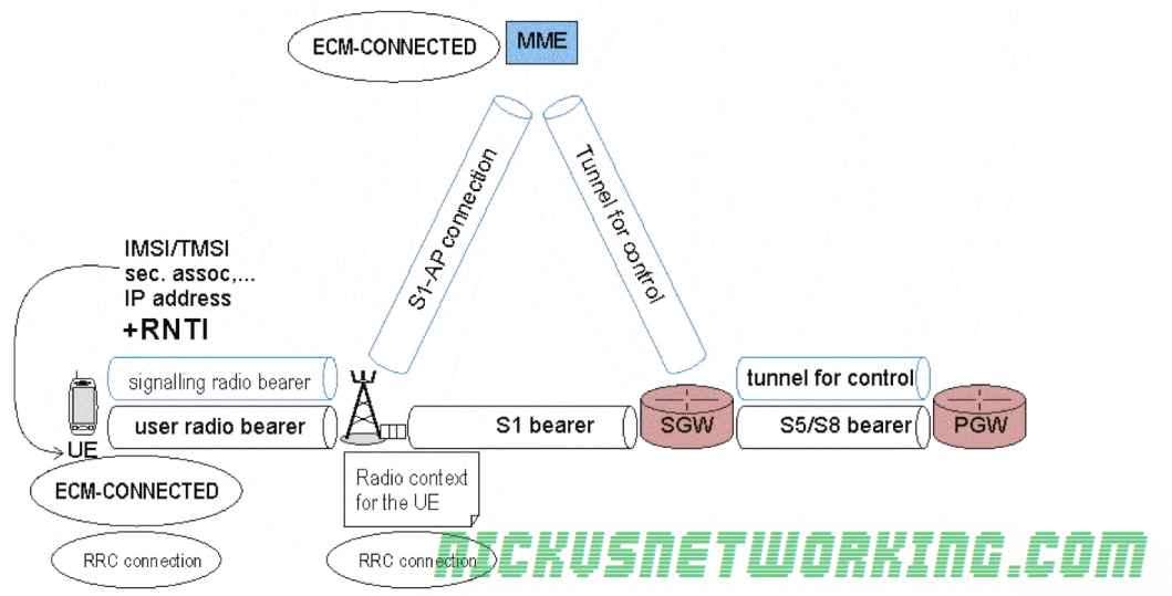
As we discussed before when no data has been sent by a UE for a period of time the eNB will switch from an ECM-Connected state to an ECM-Idle state where there is no radio connection.
ECM-Connected state
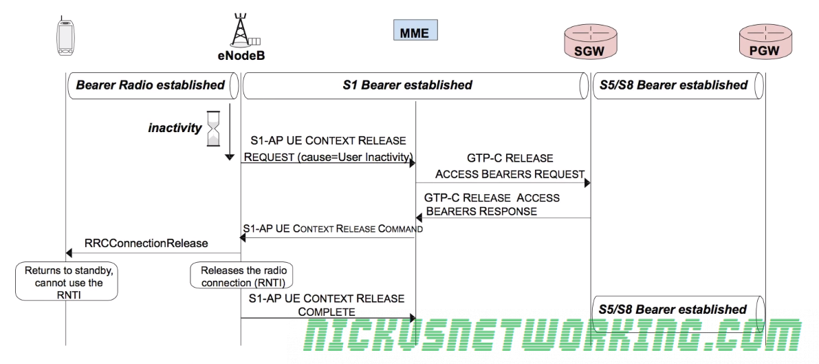
So let’s look at the release procedure.
When the transmission timeout (typically 10 – 30 seconds) has expired, meaning a user hasn’t sent data for that length of time, the eNB sends the MME a S1-AP UE Context Release Request with the cause of User Inactivity to denote why the change is being made.
The MME then sends a GTP-C message requesting release of the tunnel between the S-GW and the eNB (GTP-C Release request).
The S-GW sends back a GTP-C Release Access Bearers response, indicating it has cleared down the GTP tunnel between itself and the eNB,
The MME then sends a S1-AP UE Context Release Command to the eNB, and the eNB sends an RRCConnectionRelease which releases the RNTI assigned to that UE removing it’s radio resources.
Finally a S1-AP UE Context Release Complete is sent from eNB to the MME to let the MME know the process has completed.
Release procedure
At this stage the RNTI is no longer active so the UE cannot use the RNTI and therefore cannot be assigned radio resources.
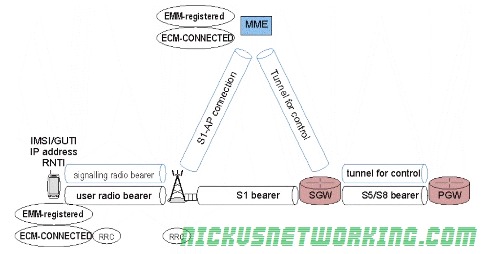
The UE is now in ECM_Idle mode, however as it still has an IP Address allocated and can be bought back it’s in EMM_Regsitered mode.
States
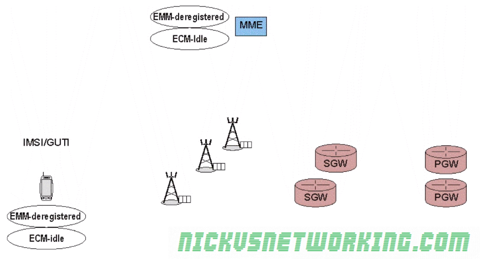
EMM-Deregistered State
UE is disconnected from the network with no radio resources and does not have an IP Address
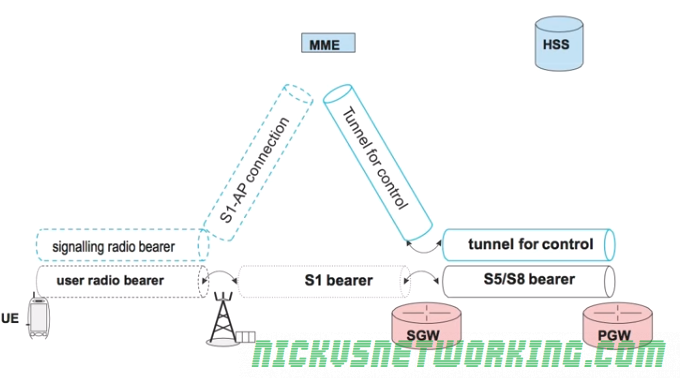
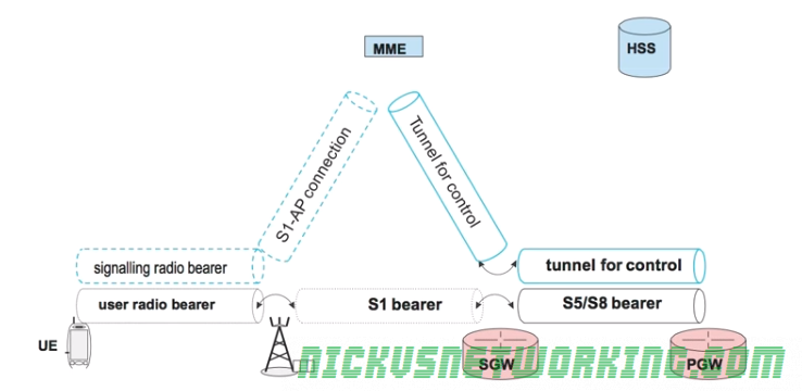
EMM-Registered & ECM-Connected
UE is connected to the network with an IP address
Radio resources (RNTI allocated)
Location of the UE known
All tunnels & connections established
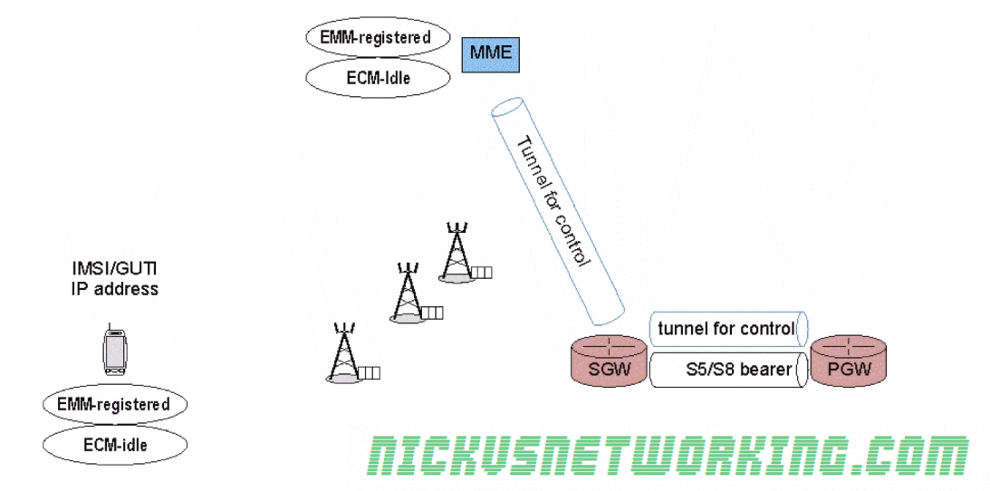
EMM-Regsitered & ECM-Idle
UE has an IP address & appears to be connected
No radio resources (RNTI) currently in use
No tunnels or connection from the eNB to the S-GW & MME.
Tunnel between S-GW and P-GW and the tunnel between the MME and S-GW
A relative location (tracking area) of the UE is available
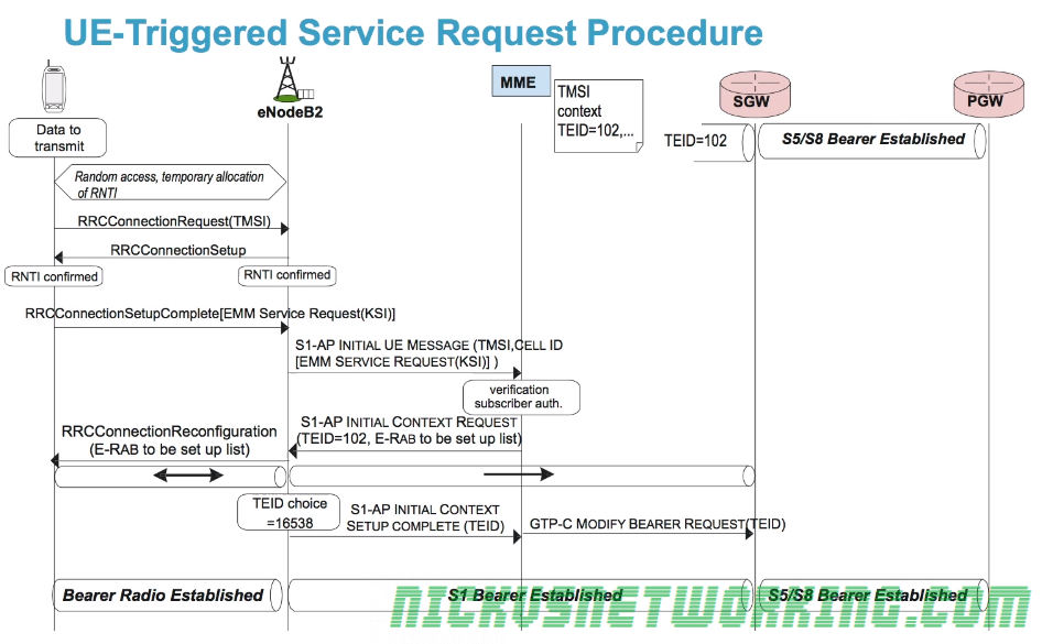
As we just saw when a terminal moves to ECC-Idle while in EMM-Registered state, it releases it’s radio resources, so what happens when the UE needs to send / receive data again?
UE is disconnected from Radio Resources (ECM-Idle & EMM Registered)
While one option could have been to go through the full attach procedure again when the UE is triggered, the 3GPP team wanted the re-connection process to be as fast as possible.
As we saw in the last post we don’t drop the S-GW <-> P-GW tunnel, which saves time on re-establishing a connection. The S1 tunnel is also not completely released; the TEID value from the S-GW end of the tunnel is saved by the MME so it can be reused by the new tunnel when the UE reconnects, without needing to inform the S-GW.
One of the common themes we cover over and over in the 4G discussion is the desire to preserve energy on the UE RF side of things, to extend battery life as much as possible.
The 3GPPs requirements for LTE also included the smallest round trip times, defining less than 5 ms in unload condition, so traffic to the UE must be routed as quickly as possible.
Mobiles are by their very nature, mobile.
This requires UEs to constantly monitor the RF conditions and the signal measurements from different base stations so the UE can determine if it’s time to handoff to another cell due to going further from one eNB and closer to another, or another eNB offering better RF conditions (Strong signal etc).
This requires regular exchanges of messages and checks, but this would take a lot of energy and eat up battery usage.
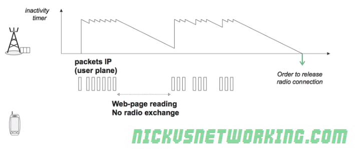
Instead we avoid maintaining the radio connection all the time with the aid of an inactivity timer on the eNB.
For as long as user data is flowing over the air interface the connection is maintained, for example web browsing, the inactivity timer is constantly reset as traffic flows.
However when the eNB detects no packets sent or received by the UE the timer starts counting down from it’s set value.
When the inactivity timer reaches 0 the RRC Connection is released and the UE no longer has an RNTI.
The UE is still listening to an eNB, it’s just not sending data to it it and visa-versa.
As the radio bearer has been removed the UE the S1-AP and S1-UP bearers between the eNB and the MME and the eNB and the S-GW respectively, can be torn down.
This means the MME is no long sure of exactly which eNB the UE is listening on.
This is referred to as ECM_IDLE state as there is no radio connection, and the network is unaware of the precise location of the UE.
An ECM_ACTIVE state is the state when the UE is connected to an eNB with an RNTI and it’s inactivity timer has not reached 0.
The dotted line bearers shown in the image above frequently change between active and inactive based on the ECM_ACTIVE / ECM_INACTIVE state of the bearers.
EPS Mobility Management (EMM) has two states – EMM-Registered (UE reachable) and EMM-Deregistered (UE not reachable).
A UE is in the deregistered state when it is not rechable, for example not currently powered up or in flight mode.
The MME memorizes the state of each UE and it’s context elements such as it’s most recent GUTI, IMSI, security parameters etc.
Attach Procedure
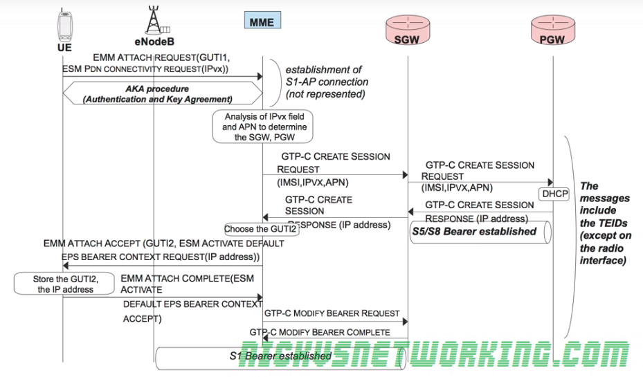
To attach to the network a UE sends an EMM Attach Request with it’s most recent GUTI to the MME.
In the same request the UE also includes an ESM PDN Connectivity Request to gain access to the external networks.
The Authentication & Key Agreement procedure is followed between the UE and the MME/HSS to authenticate the network and the subscriber.
One this is done the MME looks at the connectivity requested and the APN of the subscriber, the MME then selects a Serving-Gateway and Packet-Gateway based on the APN.
The MME then sends a GTP-C Create Session Request along with the connectivity requested (IPv4/6), APN and IMSI of the subscriber and it’s allocated TEID for this tunnel to the S-GW.
The S-GW also sends a GTP-C Create Session Request along with the connectivity requested (IPv4/6), APN and IMSI of the subscriber to the P-GW, along with the S-GW’s allocated TEID for this tunnel too.
The P-GW then sends a GTP-C Create Session back to the S-GW containing it’s TEID and it also includes the IP Address to be allocated to the UE.
A GTP session is now setup between the P-GW and the S-GW for this bearer, with the TEID values added to the TEID management tables on both devices. This GTP tunnel is referred to an S5 (home) or an S8 (roaming) Bearer in 3GPP parlance.
Another GTP-C Create Session message with it’s own TEID is also sent from the S-GW to the MME.
The MME, S-GW and P-GW now each know TEID for each of the 2 tunnels setup (MME<->S-GW, S-GW<->P-GW) so have what they need to fill their TEID management tables.
When the MME recieves the GTP-C Create Session with the IP Address for the UE it sends an EMM Attach Accept and a EPS Bearer Context Setup Request containing the IP Address the P-GW allocated to the UE to the UE itself.
The UE stores the allocated IP and sends an acknowledgement to the MME in the form of an EMM Attach Complete message back to the MME.
The MME sends a GTP-C Modify Bearer Request which transfers the bearer setup between MME and SGW and modifies it to be between the SGW and the eNB.
The S-GW sends back a GTP-C Modify Bearer Complete message and modifies the GTP tunnel to be between the SGW and the eNB. A S1 bearer is now established for carrying user data from the eNB to the SGW.
Once this procedure is complete the UE is now in the EMM Registered State meaning it is known to the MME, it has a security association and has an IP Address.
The S-GW and the P-GW also stores the TEIDs for the UE.
Detach Procedure
When a UE detaches from the network (for example it powers down), the network must release all the tunnels for that UE, the MME state must be updated to EMM Deregistered and the MME must also keep a record for the last GUTI and security keys,
To detach from the network the UE sends a RLC UL Information Transfer message containing an EMM Detach Request which includes it’s current GUTI.
As soon as the UE recivers confirmation from the eNB the UE can power down, but the eNB must inform the network of the disconnection so the resources can be released.
The eNB sends a S1Ap Uplink NAS Transport message containing a EMM Detach Request with the UE’s GUTI to the MME.
The MME can then release the security context,
The MME then sends a GTP-C Delete Session Request to the S-GW.
Upon recipt of this request the S-GW requests the P-GW tears down it’s tunnel between the P-GW and S-GW (aka the S5/S8 Bearer) by sending it’s own GTP-C Delete Session Request to the P-GW.
Once the S-GW has confirmation the tunnel has been taken down (In the form of a GTP-C Delete Session Response) the S-GW sends a GTP-C Delete Session Response to the MME.
The MME must signal to the eNB it can release the RNTI and the radio resources. To do this it sends a S1-AP UE Context Release Command which releases the radio bearers and tears down the S1-UP bearer between the eNB and the S-GW.
The eNB then sends a S1-AP UE Context Release Completeto the MME.
Finally the MME sends a Diameter Notification Request (PGW and APN Removed) to the HSS to update the HSS of the user’s status, the HSS signals back with a Diameter Notification Answer and the HSS knows the user is no longer reachable.