While reading through the 3GPP docs regarding Online Charging, there’s a concept that can be a tad confusing, and that’s the difference between Centralized and Non-Centralized Charging architectures.
The overall purpose of online charging is to answer that deceptively simple question of “does the user have enough credit for this action?”.
In order to answer that question, we need to perform rating and unit determination.
Rating
Rating is just converting connectivity credit units into monetary units.
If you go to the supermarket and they have boxes of Jaffa Cakes at $2.50 each, they have rated a box of Jaffa Cakes at $2.50.

In a non-snack-cake context, such as 3GPP Online Charging, then we might be talking about data services, for example $1 per GB is a rate for data.
Or for a voice calls a cost per minute to call a destination, such as is $0.20 per minute for a local call.
Rating is just working out the cost per connectivity unit (Data or Minutes) into a monetary cost, based on the tariff to be applied to that subscriber.
Unit Determination
The other key piece of information we need is the unit determination which is the calculation of the number of non-monetary units the OCS will offer prior to starting a service, or during a service.
This is done after rating so we can take the amount of credit available to the subscriber and calculate the number of non-monetary units to be offered.

In our rating example we rated a box of Jaffa Cakes at $2.50 per box. If I have $10 I can go to the shops and buy 4x boxes of Jaffa cakes at $2.50 per box. The cashier will perform unit determination and determine that at $2.50 per box and my $10, I can have 4 boxes of Jaffa cakes.
Again, steering away from the metaphor of the hungry author, Unit Determination in a 3GPP context could be determining how many minutes of talk time to be granted.
Question: At $0.20 per minute to a destination, for a subscriber with a current credit of $20, how many minutes of talk time should they be granted?
Answer: 100 minutes ($20 divided by $0.20 per minute is 100 minutes).
Or to put this in a data perspective,
Question: Subscriber has $10 in Credit and data is rated at $1 per GB. How many GB of data should the subscriber be allowed to use?
Answer: 10GB.
Putting this Together
So now we understand rating (working out the conversion of connectivity units into monetary units) and unit determination (determining the number of non-monetary units to be granted for a given resource), let’s look at the the Centralized and Decentralized Online Charging.
Centralized Rating
In Centralized Rating the CTF (Our P-GW or S-CSCF) only talk about non-monetary units.
There’s no talk of money, just of the connectivity units used.
The CTFs don’t know the rating information, they have no idea how much 1GB of data costs to transfer in terms of $$$.
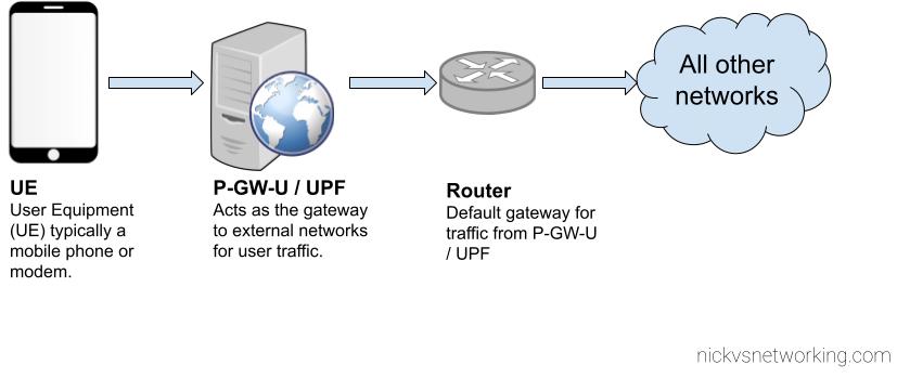
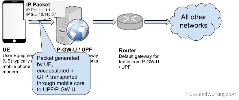
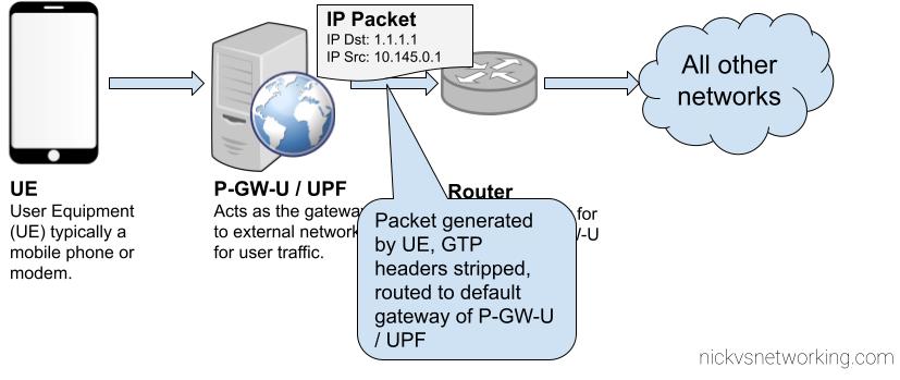
For the CTF in the P-GW/PCEF this means it talks to the OCS in terms of data units (data In/out), not money.
For the CTF in the S-CSCF this means it only ever talks to the OCS in voice units (minutes of talk time), not money.
This means our rates only need to exist in the OCS, not in the CTF in the other network elements. They just talk about units they need.
De-Centralized Rating
In De-Centralized Rating the CTF performs the unit conversion from money into connectivity units.
This means the OCS and CTF talk about Money, with the CTF determining from that amount of money granted, what the subscriber can do with that money.
This means the CTF in the S-CSCF needs to have a rating table for all the destinations to determine the cost per minute for a call to a destination.
And the CTF in the P-GW/PCEF has to know the cost per octet transferred across the network for the subscriber.
In previous generations of mobile networks it may have been desirable to perform decentralized rating, as you can spread the load of calculating our the pricing, however today Centralized is the most common way to approach this, as ensuring the correct rates are in each network element is a headache.
Centralized Unit Determination
In Centralized Unit Determination the CTF tells the OCS the type of service in the Credit Control Request (Requested Service Units), and the OCS determines the number of non-monetary units of a certain service the subscriber can consume.
The CTF doesn’t request a value, just tells the OCS the service being requested and subscriber, and the OCS works out the values.
For example, the S-CSCF specifies in the Credit Control Request the destination the caller wishes to reach, and the OCS replies with the amount of talk time it will grant.
Or for a subscriber wishing to use data, the P-GW/PCEF sends a Credit Control Request specifying the service is data, and the OCS responds with how much data the subscriber is entitled to use.
De-Centralized Unit Determination
In De-Centralized Unit Determination, the CTF determines how many units are required to start the service, and requests these units from the OCS in the Credit Control Request.
For a data service,the CTF in the P-GW would determine how many data units it is requesting for a subscriber, and then request that many units from the OCS.
For a voice call a S-CSCF may request an initial call duration, of say 5 minutes, from the OCS. So it provides the information about the destination and the request for 300 seconds of talk time.
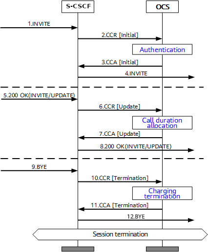
Session Charging with Unit Reservation (SCUR)
Arguably the most common online charging scenario is Session Charging with Unit Reservation (SCUR).
SCUR relies on reserving an amount of funds from the subscriber’s balance, so no other services can those funds and translating that into connectivity units (minutes of talk time or data in/out based on the Requested Session Unit) at the start of the session, and then subsequent requests to debit the reserved amount and reserve a new amount, until all the credit is used.
This uses centralized Unit Determination and centralized Rating.
Let’s take a look at how this would look for the CTF in a P-GW/PCEF performing online charging for a subscriber wishing to use data:
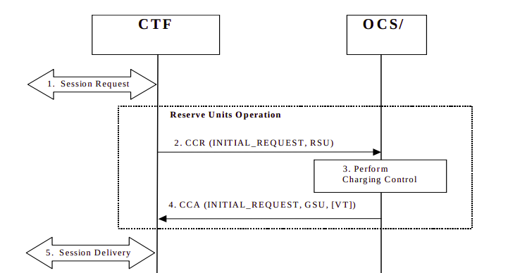
- Session Request: The subscriber has attached to the network and is requesting service.
- The CTF built into the P-GW/PCEF sends a Credit Control Request: Initial Request (As this subscriber has just attached) to the OCS, with Requested Service Units (RSU) of data in/out to the OCS.
- The OCS performs rating and unit determination, and according to it’s credit risk policies, and a whole lot of other factors, comes back with an amount of data the subscriber can use, and reserves the amount from the account.
(It’s worth noting at this point that this is not necessarily all of the subscriber’s credit in the form of data, just an amount the OCS is willing to allocate. More data can be requested once this allocated data is used up.) - The OCS sends a Credit Control Answer back to our P-GW/PCEF. This contains the Granted Service Unit (GSU), in our case the GSU is data so defines much data up/down the user can transfer. It also may include a Validity Time (VT), which is the number of seconds the Credit Control Answer is valid for, after it’s expired another Credit Control Request must be sent by the CTF.
- Our P-GW/PCEF processes this, starts measuring the data used by the subscriber for reporting later, and sets a timer for the Validity Time to send another CCR at that point.
At this stage, our subscriber is able to start using data.
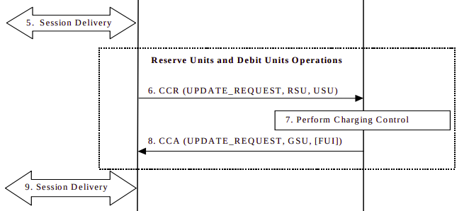
- Some time later, either when all the data allocated in the Granted Service Units has been consumed, or when the Validity Time has expired, the CTF in the P-GW/PCEF sends another Credit Control Request: Update, and again includes the RSU (Requested Service Units) as data in/out, and also a USU (Used Service Units) specifying how much data the subscriber has used since the first Credit Control Answer.
- The OCS receives this information. It compares the Used Session Units to the Granted Session Units from earlier, and with this is able to determine how much data the subscriber has actually used, and therefore how much credit that equates to, and debit that amount from the account.
With this information the OCS can reserve more funds and allocate another GSU (Granted Session Unit) if the subscriber has the required balance. If the subscriber only has a small amount of credit left the FUI (Final Unit Indication AVP) is set to determine this is all the subscriber has left in credit, and if this is exhausted to end the session, rather than sending another Credit Control Request. - The Credit Control Answer with new GSU and the FUI is sent back to the P-GW/PCEF
- The P-GW/PCEF allows the session to continue, again monitoring used traffic against the GSU (Granted Session Units).
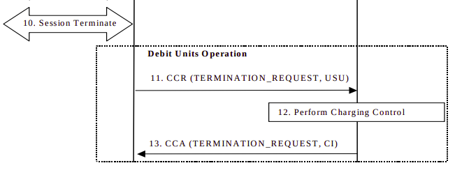
- Once the subscriber has used all the data in the Granted Session Units, and as the last CCA included the Final Unit Indicator, the CTF in the P-GW/PCEF knows it can’t just request more credit in the form of a CCR Update, so cuts of the subscribers’s session.
- The P-GW/PCEF then sends a Credit Control Request: Termination Request with the final Used Service Units to the OCS.
- The OCS debits the used service units from the subscriber’s balance, and refunds any unused credit reservation.
- The OCS sends back a Credit Control Answer which may include the CI value for Credit Information, to denote the cost information which may be passed to the subscriber if required.