PDU Session Type: The type of PDU Session which can be IPv4, IPv6, IPv4v6, Ethernet or Unstructured
ETSI TS 123 501 – System Architecture for the 5G System
No longer are we limited to just IP transport, meaning at long last I can transport my Token Ring traffic over 5G, or in reality, customers can extend Layer 2 networks (Ethernet) over 3GPP technologies, without resorting to overlay networking, and much more importantly, fixed line networks, typically run at Layer 2, can leverage the 5G core architecture.
How does this work?
With TFTs and the N6 interfaces relying on the 5 value tuple with IPs/Ports/Protocol #s to make decisions, transporting Ethernet or Non-IP Data over 5G networks presents a problem.
But with fixed (aka Wireline) networks being able to leverage the 5G core (“Wireline Convergence”), we need a mechanism to handle Ethernet.
For starters in the PDU Session Establishment Request the UE indicates which PDN types, historically this was IPv4/6, but now if supported by the UE, Ethernet or Unstructured are available as PDU types.
We’ll focus on Ethernet as that’s the most defined so far,
Once an Ethernet PDU session has been setup, the N6 interface looks a bit different, for starters how does it know where, or how, to route unstructured traffic?
As far as 3GPP is concerned, that’s your problem:
Regardless of addressing scheme used from the UPF to the DN, the UPF shall be able to map the address used between the UPF and the DN to the PDU Session.
5.6.10.3 Support of Unstructured PDU Session type
In short, the UPF will need to be able to make the routing decisions to support this, and that’s up to the implementer of the UPF.
In the Ethernet scenario, the UPF would need to learn the MAC addresses behind the UE, handle ARP and use this to determine which traffic to send to which UE, encapsulate it into trusty old GTP, fill in the correct TEID and then send it to the gNodeB serving that user (if they are indeed on a RAN not a fixed network).
So where does this leave QoS? Without IPs to apply with TFTs and Packet Filter Sets to, how is this handled? In short, it’s not – Only the default QoS rule exist for a PDU Session of Type Unstructured. The QoS control for Unstructured PDUs is performed at the PDU Session level, meaning you can set the QFI when the PDU session is set up, but not based on traffic through that bearer.
Does this mean 5G RAN can transport Ethernet?
Well, it remains to be seen.
The specifications don’t cover if this is just for wireline scenarios or if it can be used on RAN.
The 5G PDU Creation signaling has a field to indicate if the traffic is Ethernet, but to work over a RAN we would need UE support as well as support on the Core.
And for E-UTRAN?
For the foreseeable future we’re going to be relying on LTE/E-UTRAN as well as 5G. So if you’re mobile with a non-IP PDU, and you enter an area only served by LTE, what happens?
PDU Session types “Ethernet” and “Unstructured” are transferred to EPC as “non-IP” PDN type (when supported by UE and network). … It is assumed that if a UE supports Ethernet PDU Session type and/or Unstructured PDU Session type in 5GS it will also support non-IP PDN type in EPS.
5.17.2 Interworking with EPC
If you were not aware of support in the EPC for Non-IP PDNs, I don’t blame you – So far support the CIoT EPS optimizations were initially for Non-IP PDN type has been for NB-IoT to supporting Non-IP Data Delivery (NIDD) for lightweight LwM2M traffic.
So why is this? Well, it may have to do with WO 2017/032399 Al which is a patent held by Ericsson, regarding “COMMUNICATION OF NON-IP DATA OVER PACKET DATA NETWORKS” which may be restricting wide scale deployment of this,
As Open5Gs has introduced network slicing, which led to a change in the database used,
Alas many users had subscribers provisioned in the old DB schema and no way to migrate the SDM data between the old and new schema,
If you’ve created subscribers on the old schema, and now after the updates your Subscriber Authentication is failing, check out this tool I put together, to migrate your data over.
I’d been trying for some time to get Kamailio acting as a Diameter Routing Agent with mixed success, and eventually got it working, after a few changes to the codebase of the ims_diameter_server module.
It is rather unstable, in that if it fails to dispatch to a Diameter peer, the whole thing comes crumbling down, but incoming Diameter traffic is proxied off to another Diameter peer, and Kamailio even adds an extra AVP.
Having used Kamailio for so long I was really hoping I could work with Kamailio as a DRA as easily as I do for SIP traffic, but it seems the Diameter module still needs a lot more love before it’ll be stable enough and simple enough for everyone to use.
I created a branch containing the fixes I made to make it work, and with an example config for use, but use with caution. It’s a long way from being production-ready, but hopefully in time will evolve.
One feature I’m pretty excited to share is the addition of a single config file for defining how PyHSS functions,
In the past you’d set variables in the code or comment out sections to change behaviour, which, let’s face it – isn’t great.
Instead the config.yaml file defines the PLMN, transport time (TCP or SCTP), the origin host and realm.
We can also set the logging parameters, SNMP info and the database backend to be used,
HSS Parameters
 hss:
   transport: "SCTP"
   #IP Addresses to bind on (List) - For TCP only the first IP is used, for SCTP all used for Transport (Multihomed).
   bind_ip: ["10.0.1.252"]
 #Port to listen on (Same for TCP & SCTP)
   bind_port: 3868
 #Value to populate as the OriginHost in Diameter responses
   OriginHost: "hss.localdomain"
 #Value to populate as the OriginRealm in Diameter responses
   OriginRealm: "localdomain"
 #Value to populate as the Product name in Diameter responses
   ProductName: "pyHSS"
 #Your Home Mobile Country Code (Used for PLMN calcluation)
   MCC: "999"
   #Your Home Mobile Network Code (Used for PLMN calcluation)
   MNC: "99"
 #Enable GMLC / SLh Interface
   SLh_enabled: True


 logging:
   level: DEBUG
   logfiles:
     hss_logging_file: log/hss.log
     diameter_logging_file: log/diameter.log
     database_logging_file: log/db.log
   log_to_terminal: true

 database:
   mongodb:
     mongodb_server: 127.0.0.1
     mongodb_username: root
     mongodb_password: password
     mongodb_port: 27017

 Stats Parameters
 redis:
   enabled: True
   clear_stats_on_boot: False
   host: localhost
   port: 6379
 snmp:
   port: 1161
   listen_address: 127.0.0.1
MSISDN AVP 700 / vendor ID 10415, used to advertise the subscriber’s MSISDN in signaling.
I formatted the data as an Octet String, with the MSISDN from the database and moved on my merry way.
Not so fast…
The MSISDN AVP is of type OctetString.
This AVP contains an MSISDN, in international number format as described in ITU-T Rec E.164 [8], encoded as a TBCD-string, i.e. digits from 0 through 9 are encoded 0000 to 1001;
1111 is used as a filler when there is an odd number of digits; bits 8 to 5 of octet n encode digit 2n; bits 4 to 1 of octet n encode digit 2(n-1)+1.
ETSI TS 129 329 / 6.3.2 MSISDN AVP
Come again?
In practice this means if you have an odd lengthed MSISDN value, we need to add some padding to round it out to an even-lengthed value.
This padding happens between the last and second last digit of the MSISDN (because if we added it at the start we’d break the Country Code, etc) and as MSISDNs are variable length subscriber numbers.
1111 in octet string is best known as the letter F,
A seperate server (hss_sctp.py) is run to handle SCTP connections, and if you’re looking for Multihoming, we got you dawg – Just edit the config file and set the bind_ip list to include each of your IPs to multi home listen on.
Ok, admittedly I haven’t actually seen “When a Stranger Calls”, or the less popular sequel “When a stranger Redials” (Ok may have made the last one up).
But the premise (as I read Wikipedia) is that the babysitter gets the call on the landline, and the police trace the call as originating from the landline.
But you can’t phone yourself, that’s not how local loops work – When the murderer goes off hook it loops the circuit, which busys it. You could apply ring current to the line I guess externally but unless our murder has a Ring generator or has setup a PBX inside the house, the call probably isn’t coming from inside the house.
On Topic – The GMLC
The GMLC (Gateway Mobile Location Centre) is a central server that’s used to locate subscribers within the network on different RATs (GSM/UMTS/LTE/NR).
The GMLC typically has interfaces to each of the radio access technologies, there is a link between the GMLC and the CS network elements (used for GSM/UMTS) such as the HLR, MSC & SGSN via Lh & Lg interfaces, and a link to the PS network elements (LTE/NR) via Diameter based SLh and SLg interfaces with the MME and HSS.
The GMLC’s tentacles run out to each of these network elements so it can query them as to a subscriber’s location,
LTE Call Flow
To find a subscriber’s location in LTE Diameter based signaling is used, to query the MME which in turn queries, the eNodeB to find the location.
But which MME to query?
The SLh Diameter interface is used to query the HSS to find out which MME is serving a particular Subscriber (identified by IMSI or MSISDN).
The LCS-Routing-Info-Request is sent by the GMLC to the HSS with the subscriber identifier, and the LCS-Routing-Info-Response is returned by the HSS to the GMLC with the details of the MME serving the subscriber.
Now we’ve got the serving MME, we can use the SLgDiameter interface to query the MME to the location of that particular subscriber.
The MME can report locations to the GMLC periodically, or the GMLC can request the MME provide a location at that point. For the GMLC to request a subscriber’s current location a Provide-Location-Request is set by the GMLC to the MME with the subscriber’s IMSI, and the MME responds after querying the eNodeB and optionally the UE, with the location info in the Provide-Location-Response.
(I’m in the process of adding support for these interfaces to PyHSS and all going well will release some software shortly to act at a GMLC so people can use this.)
Finding the actual Location
There are a few different ways the actual location of the UE is determined,
At the most basic level, Cell Global Identity (CGI) gives the identity of the eNodeB serving a user. If you’ve got a 3 sector site each sector typically has its own Cell Global Identity, so you can determine to a certain extent, with the known radiation pattern, bearing and location of the sector, in which direction a subscriber is. This happens on the network side and doesn’t require any input from the UE. But if we query the UE’s signal strength, this can then be combined with existing RF models and the signal strength reported by the UE to further pinpoint the user with a bit more accuracy. (Uplink and downlink cell coverage based positioning methods) Barometric pressure and humidity can also be reported by the base station as these factors will impact resulting signal strengths.
Timing Advance (TA) and Time of Arrival (TOA) both rely on timing signals to/from a UE to determine it’s distance from the eNodeB. If the UE is only served by a single cell this gives you a distance from the cell and potentially an angle inside which the subscriber is. This becomes far more useful with 3 or more eNodeBs in working range of the UE, where you can “triangulate” the UE’s location. This part happens on the network side with no interaction with the UE. If the UE supports it, EUTRAN can uses Enhanced Observed Time Difference (E-OTD) positioning method, which does TOD calcuation does this in conjunction with the UE.
GPS Assisted (A-GPS) positioning gives good accuracy but requires the devices to get it’s current location using the GPS, which isn’t part of the baseband typically, so isn’t commonly implimented.
Uplink Time Difference of Arrival (UTDOA) can also be used, which is done by the network.
So why do we need to get Subscriber Locations?
The first (and most noble) use case that springs to mind is finding the location of a subscriber making a call to emergency services. Often upon calling an emergency services number the GMLC is triggered to get the subscriber’s location in case the call is cut off, battery dies, etc.
But GMLCs can also be used for lots of other purposes, marketing purposes (track a user’s location and send targeted ads), surveillance (track movements of people) and network analytics (look at subscriber movement / behavior in a specific area for capacity planning).
Different countries have different laws regulating access to the subscriber location functions.
Hack to disable Location Reporting on Mobile Networks
If you’re wondering how you can disable this functionality, you can try the below hack to ensure that your phone does not report your location.
Press the power button on your phone
Turn it off
In reality, no magic super stealth SIM cards, special phones or fancy firmware will prevent the GMLC from finding your location. So far none of the “privacy” products I’ve looked at have actually done anything special at the Baseband level. Most are just snakeoil.
For as long as your device is connected to the network, the passive ways of determining location, such as Uplink Time Difference of Arrival (UTDOA) and the CGI are going to report your location.
Every now and then when looking into a problem I have to really stop and think about how things work low down, that I haven’t thought about for a long time, and MTU is one of those things.
I faced with an LTE MTU issue recently I thought I’d go back and brush up on my MTU knowhow and do some experimenting.
Note: This is an IPv4 discussion, IPv6 does not support fragmentation.
The very, very basics
MTU is the Maximum Transmission Unit.
In practice this is the largest datagram the layer can handle, and more often than not, this is based on a physical layer constraint, in that different physical layers can only stuff so much into a frame.
“The Internet” from a consumer perspective typically has an MTU of 1500 bytes or perhaps a bit under depending on their carrier, such as 1472 bytes. SANs in data centers typically use an MTU of around 9000 bytes, Out of the box, most devices if you don’t specify, will use an MTU of 1500 bytes.
As a general rule, service providers typically try to offer an MTU as close to 1500 as possible.
Messages that are longer than the Maximum Transmission Unit need to be broken up in a process known as “Fragmenting”. Fragmenting allows large frames to be split into smaller frames to make their way across hops with a lower MTU.
All about Fragmentation
So we can break up larger packets into smaller ones by Fragmenting them, so case closed on MTU right? Sadly not.
Fragmentation leads to reduced efficiency – Fragmenting frames takes up precious CPU cycles on the router performing it, and each time a frame is broken up, additional overhead is added by the device breaking it up, and by the receiver to reassemble it.
Fragmentation can happen multiple times across a path (Multi-Stage Fragmentation). For example if a frame is sent with a length of 9000 bytes, and needs to traverse a hop with an MTU of 4000, it would need to be fragmented (broken up) into 3 frames (Frame 1 and Frame 2 would be ~4000 bytes long and frame 3 would be ~1000 bytes long). If it then needs to traverse another hop with an MTU of 1500, then the 3 fragmented frame would each need to be further fragmented, with the first frame of ~4000 bytes being split up into 3 more fragmented frames. Lost track of what just happened? Spare a thought for the routers having to to do the fragmentation and the recipient having to reassemble their packets.
Fragmented frames are reassembled by the end recipient, other devices along the transmission path don’t reassemble packets.
In the end it boils down to this trade off: The larger the packet can be, the more user data we can stuff into each one as a percentage of the overall data. We want the percentage of user data for each packet to be as high as can be. This means we want to use the largest MTU possible, without having to fragment packets.
Overhead eats into our MTU
A 1500 byte MTU that has to be encapsulated in IPsec, GTP or PPP, is no longer a 1500 byte MTU as far as the customer is concerned.
Any of these encapsulation techniques add overhead, which shrinks the MTU available to the end customer.
This means we’ve got 50 bytes of transmission / transport overhead. This will be important later on!
How do subscribers know what to use as MTU?
Typically when a subscriber buys a DSL service or HFC connection, they’ll either get a preconfigured router from their carrier, or they will be given a list of values to use that includes MTU.
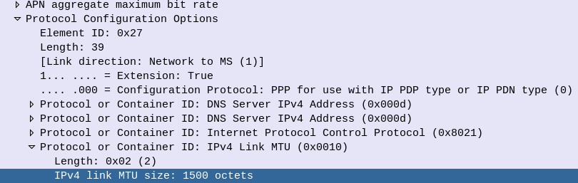
LTE and 5G on the other hand tell us the value we should use.
Inside the Protocol Configuration Options in the NAS PDU, the UE requests the MTU and DNS server to be used, and is provided back from the network.
This MTU value is actually set on the MME, not the P-GW. As the MME doesn’t actually know the maximum MTU of the network, it’s up to the operator to configure this to be a value that represents the network.
Why this Matters for LTE & 5G Transmission
As we covered earlier, fragmentation is costly. If we’re fragmenting packets we are:
Wasting resources on our transmission network / core networks – as we fragment Subscriber packets it’s taking up compute resources and therefore limiting throughput
Wasting radio resources as additional overhead is introduced for fragmented packets, and additional RBs need to be scheduled to handle the fragmented packets
To test this I’ve setup a scenario in the lab, and we’ll look at the packet captures to see how the MTU is advertised, and see how big we can make our MTU on the subscriber side.
I never cease to be amazed as to what I can do with Wireshark.
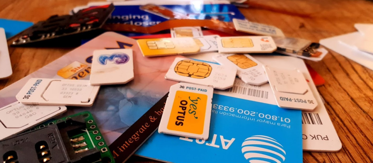
While we’re working with Smart Card readers and SIM cards, capturing and Decoding USB traffic to see what APDUs are actually being sent can be super useful, so in this post we’ll look at how we can use Wireshark to sniff the USB traffic to view APDUs being sent to smart cards from other software.
For the purposes of this post I’ll be reading the SIM cards with pySim, but in reality it’ll work with any proprietary SIM software, allowing you to see what’s actually being said to the card by your computer.
If you want to see what’s being sent between your phone and SIM card, the Osmocom SIMtrace is the device for you (And yes it also uses Wireshark for viewing this data!).
Ok, that’s all the prerequisites sorted, next we need to find the bus and device ID of our smart card reader,
We can get this listed with
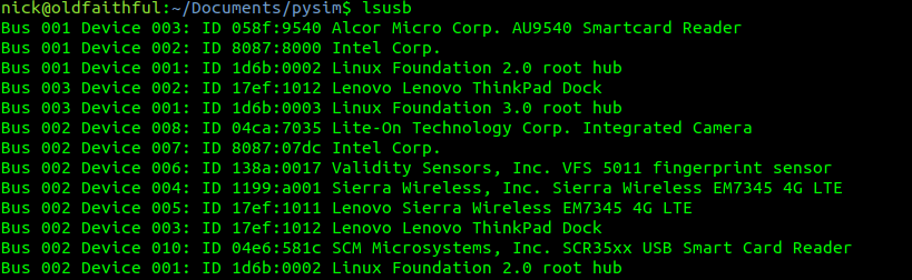
lsusb
Here you can see I have a Smart Card reader on Bus 1 device 03 and another on Bus 2 device 10.
The reader I want to use is the “SCM Microsystems, Inc. SCR35xx USB Smart Card Reader” so I’ll jott down Bus 2 device 10. Yours will obviously be different, but you get the idea.
Finding the USB traffic in Wireshark
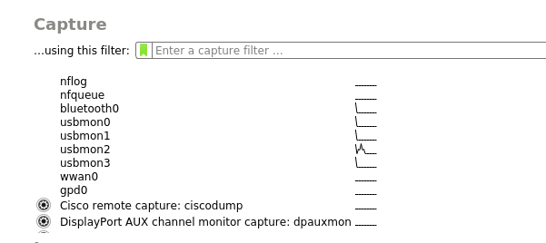
Next we’ll fire up Wireshark, if you’ve got your permissions right and followed along, you should see a few more interfaces starting with usbmonX in the capture list.
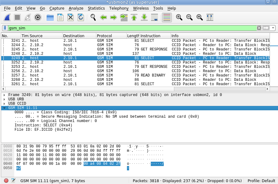
Because the device I want to capture from is on Bus 2, we’ll select usbmon2 and start capturing,
As you can see we’ve got a bit of a firehose of data, and we only care about device 10 on bus 2, so let’s filter for that.
So let’s generate some data and then filter for it, to generate some data I’m going to run pySim-read to read the data on a smart card that’s connected to my PC, and then filter to only see traffic on that USB device,
In my case as the USB device is 10 it’s got two sub addresses, so I’ll filter for USB Bus 2, device 10 sub-address 1 and 2, so the filter I’ll use is:
usb.addr=="2.10.1" or usb.addr=="2.10.2"
But this doesn’t really show us much, so let’s tell Wireshark this is PCSC/UCCID data to decode it as such;
So we’ll select some of this traffic -> Decode as -> USBCCID
Still not seeing straight APDUs, so let’s tell Wireshark one more bit of information – That we want to decode this information as GSM SIM data;
Again, we’ll select the data part of the USBCCID traffic -> Decode As -> GSM_SIM
And bingo, just like that we can now filter by gsm_sim and see the APDUs being sent / received.
This is part 3 of an n part tutorial series on working with SIM cards.
So in our last post we took a whirlwind tour of what an APDU does, is, and contains.
Interacting with a card involves sending the APDU data to the card as hex, which luckily isn’t as complicated as it seems.
While reading what the hex should look like on the screen is all well and good, actually interacting with cards is the name of the game, so that’s what we’ll be doing today, and we’ll start to abstract some of the complexity away.
Getting Started
To follow along you will need:
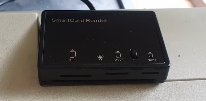
A Smart Card reader – SIM card / Smart Card readers are baked into some laptops, some of those multi-card readers that read flash/SD/CF cards, or if you don’t have either of these, they can be found online very cheaply ($2-3 USD).
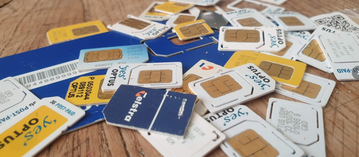
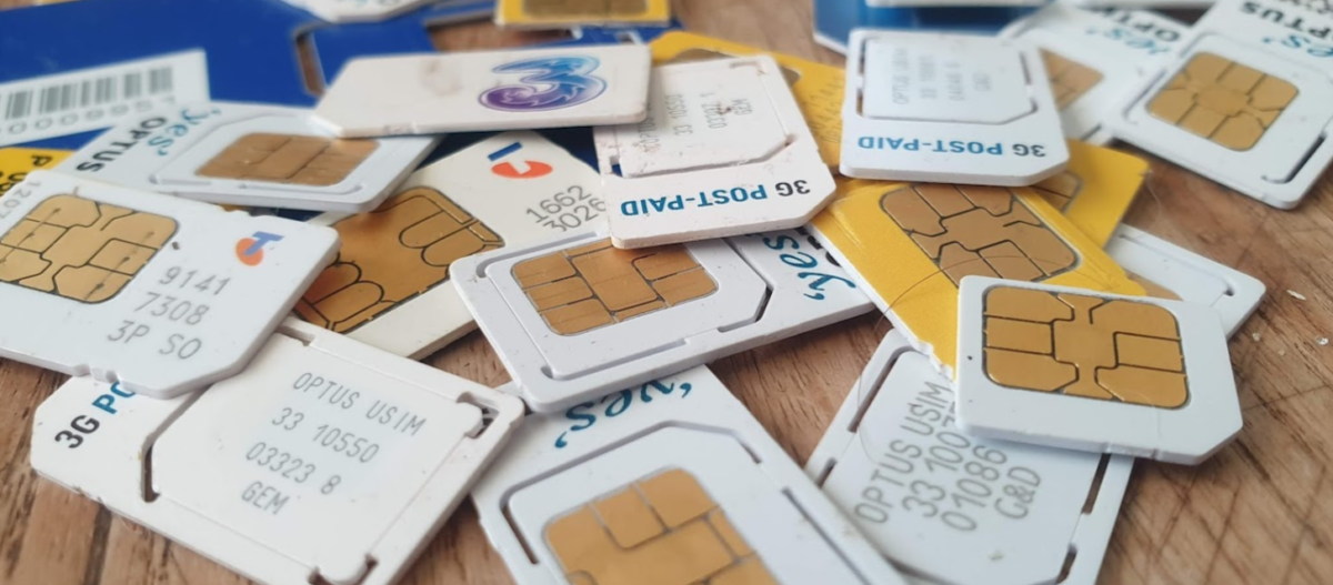
A SIM card – No need to worry about ADM keys or anything fancy, one of those old SIM cards you kept in the draw because you didn’t know what to do with them is fine, or the SIM in our phone if you can find the pokey pin thing. We won’t go breaking anything, promise.
You may end up fiddling around with the plastic adapters to change the SIM form factor between regular smart card, SIM card (standard), micro and nano.
USB SIM / Smart Card reader supports all the standard form factors makes life a lot easier!
To keep it simple, we’re not going to concern ourselves too much with the physical layer side of things for interfacing with the card, so we’ll start with sending raw APDUs to the cards, and then we’ll use some handy libraries to make life easier.
PCSC Interface
To abstract away some complexity we’re going to use the industry-standard PCSC (PC – Smart Card) interface to communicate with our SIM card. Throughout this series we’ll be using a few Python libraries to interface with the Smart Cards, but under the hood all will be using PCSC to communicate.
pyscard
I’m going to use Python3 to interface with these cards, but keep in mind you can find similar smart card libraries in most common programming languages.
At this stage as we’re just interfacing with Smart Cards, our library won’t have anything SIM-specific (yet).
We’ll use pyscard to interface with the PCSC interface. pyscard supports Windows and Linux and you can install it using PIP with:
pip install pyscard
So let’s get started by getting pyscard to list the readers we have available on our system:
#!/usr/bin/env python3
from smartcard.System import *
print(readers())
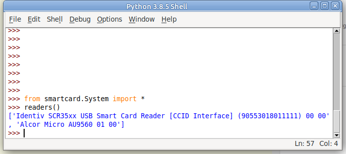
Running this will output a list of the readers on the system:
Here we can see the two readers that are present on my system (To add some confusion I have two readers connected – One built in Smart Card reader and one USB SIM reader):
(If your device doesn’t show up in this list, double check it’s PCSC compatible, and you can see it in your OS.)
So we can see when we run readers() we’re returned a list of readers on the system.
I want to use my USB SIM reader (The one identified by Identiv SCR35xx USB Smart Card Reader CCID Interface 00 00), so the next step will be to start a connection with this reader, which is the first in the list.
So to make life a bit easier we’ll store the list of smart card readers and access the one we want from the list;
#!/usr/bin/env python3
from smartcard.System import *
r = readers()
connection = r[0].createConnection()
connection.connect()
So now we have an object for interfacing with our smart card reader, let’s try sending an APDU to it.
Actually Doing something Useful
Today we’ll select the EF that contains the ICCID of the card, and then we will read that file’s binary contents.
This means we’ll need to create two APDUs, one to SELECT the file, and the other to READ BINARY to get the file’s contents.
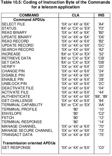
We’ll set the instruction byte to A4 to SELECT, and B0 to READ BINARY.
Table of Instruction bytes from TS 102 221
APDU to select EF ICCID
The APDU we’ll send will SELECT (using the INS byte value of A4 as per the above table) the file that contains the ICCID.
Each file on a smart card has been pre-created and in the case of SIM cards at least, is defined in a specification.
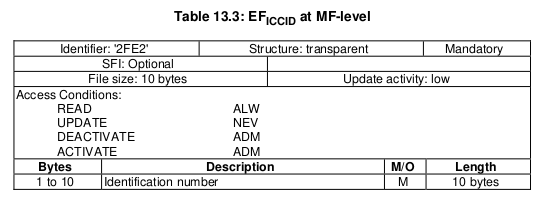
For this post we’ll be selecting the EF ICCID, which is defined in TS 102 221.
Information about EF-ICCID from TS 102 221
To select it we will need it’s identifier aka File ID (FID), for us the FID of the ICCID EF is 2FE2, so we’ll SELECT file 2FE2.
Parameter 1 – Selection Control (Limit search options)
00 (Select by File ID)
P2
Parameter 1 – More selection options
04 (No data returned)
Lc
Length of Data
02 (2 bytes of data to come)
Data
File ID of the file to Select
2FE2 (File ID of ICCID EF)
So that’s our APDU encoded, it’s final value will be A0 A4 00 04 02 2FE2
So let’s send that to the card, building on our code from before:
#!/usr/bin/env python3
from smartcard.System import *
from smartcard.util import *
r = readers()
connection = r[0].createConnection()
connection.connect()

print("Selecting ICCID File")
data, sw1, sw2 = connection.transmit(toBytes('00a40004022fe2'))
print("Returned data: " + str(data))
print("Returned Status Word 1: " + str(sw1))
print("Returned Status Word 2: " + str(sw2))
If we run this let’s have a look at the output we get,
We got back:
Selecting ICCID File
 Returned data: []
 Returned Status Word 1: 97
 Returned Status Word 2: 33
So what does this all mean?
Well for starters no data has been returned, and we’ve got two status words returned, with a value of 97 and 33.
We can lookup what these status words mean, but there’s a bit of a catch, the values we’re seeing are the integer format, and typically we work in Hex, so let’s change the code to render these values as Hex:
#!/usr/bin/env python3
from smartcard.System import *
from smartcard.util import *
r = readers()
connection = r[0].createConnection()
connection.connect()

print("Selecting ICCID File")
data, sw1, sw2 = connection.transmit(toBytes('00a40004022fe2'))
print("Returned data: " + str(data))
print("Returned Status Word 1: " + str(hex(sw1)))
print("Returned Status Word 2: " + str(hex(sw2)))
Now we’ll get this as the output:
Selecting ICCID File Returned data: [] Returned Status Word 1: 0x61 Returned Status Word 2: 0x1e
Status Word 2 contains a value of 1e which tells us that there are 30 bytes of extra data available with additional info about the file. (We’ll cover this in a later post).
So now we’ve successfully selected the ICCID file.
Keeping in mind with smart cards we have to select a file before we can read it, so now let’s read the binary contents of the file we selected;
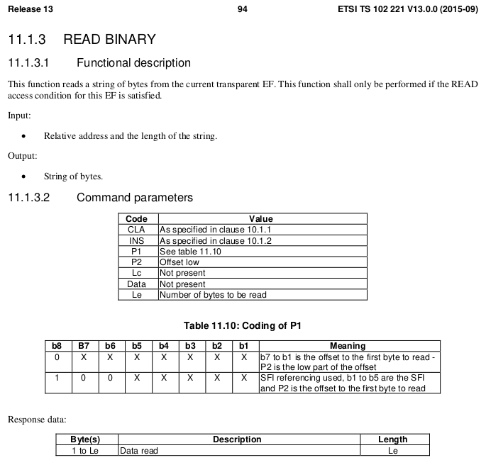
The READ BINARY command is used to read the binary contents of a selected file, and as we’ve already selected the file 2FE2 that contains our ICCID, if we run it, it should return our ICCID.
If we consult the table of values for the INS (Instruction) byte we can see that the READ BINARY instruction byte value is B0, and so let’s refer to the spec to find out how we should format a READ BINARY instruction:
Code
Meaning
Value
CLA
Class bytes – Coding options
A0 (ISO 7816-4 coding)
INS
Instruction (Command) to be called
B0 (READ BINARY)
P1
Parameter 1 – Coding / Offset
00 (No Offset)
P2
Parameter 2 – Offset Low
00
Le
How many bytes to read
0A (10 bytes of data to come)
We know the ICCID file is 10 bytes from the specification, so the length of the data to return will be 0A (10 bytes).
Let’s add this new APDU into our code and print the output:
#!/usr/bin/env python3
from smartcard.System import *
from smartcard.util import *
r = readers()
connection = r[0].createConnection()
connection.connect()

print("Selecting ICCID File")
data, sw1, sw2 = connection.transmit(toBytes('00a40000022fe2'))
print("Returned data: " + str(data))
print("Returned Status Word 1: " + str(hex(sw1)))
print("Returned Status Word 2: " + str(hex(sw2)))
And we have read the ICCID of the card.
Phew.
That’s the hardest thing we’ll need to do over.
From now on we’ll be building the concepts we covered here to build other APDUs to get our cards to do useful things. Now you’ve got the basics of how to structure an APDU down, the rest is just changing values here and there to get what you want.
In our next post we’ll read a few more files, write some files and delve a bit deeper into exactly what it is we are doing.
Australia is a strange country; As a kid I was scared of dogs, and in response, our family got a dog.
This year started off with adventures working with ASN.1 encoded data, and after a week of banging my head against the table, I was scared of ASN.1 encoding.
But now I love dogs, and slowly, I’m learning to embrace ASN.1 encoding.
What is ASN.1?
ASN.1 is an encoding scheme.
The best analogy I can give is to image a sheet of paper with a form on it, the form has fields for all the different bits of data it needs,
Each of the fields on the form has a data type, and the box is sized to restrict input, and some fields are mandatory.
Now imagine you take this form and cut a hole where each of the text boxes would be.
We’ve made a key that can be laid on top of a blank sheet of paper, then we can fill the details through the key onto the blank paper and reuse the key over and over again to fill the data out many times.
When we remove the key off the top of our paper, and what we have left on the paper below is the data from the form. Without the key on top this data doesn’t make much sense, but we can always add the key back and presto it’s back to making sense.
While this may seem kind of pointless let’s look at the advantages of this method;
The data is validated by the key – People can’t put a name wherever, and country code anywhere, it’s got to be structured as per our requirements. And if we tried to enter a birthday through the key form onto the paper below, we couldn’t.
The data is as small as can be – Without all the metadata on the key above, such as the name of the field, the paper below contains only the pertinent information, and if a field is left blank it doesn’t take up any space at all on the paper.
It’s these two things, rigidly defined data structures (no room for errors or misinterpretation) and the minimal size on the wire (saves bandwidth), that led to 3GPP selecting ASN.1 encoding for many of it’s protocols, such as S1, NAS, SBc, X2, etc.
It’s also these two things that make ASN.1 kind of a jerk; If the data structure you’re feeding into your ASN.1 compiler does not match it will flat-out refuse to compile, and there’s no way to make sense of the data in its raw form.
But working with a super simple ASN.1 definition you’ve created is one thing, using the 3GPP defined ASN.1 definitions is another,
With the aid of the fantastic PyCrate library, which is where the real magic happens, and this was the nut I cracked this week, compiling a 3GPP ASN.1 definition and communicating a standards-based protocol with it.
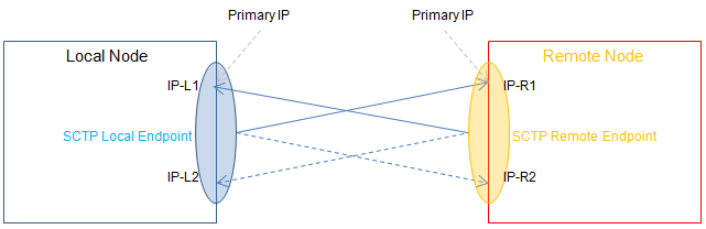
One of the key advantages of SCTP over TCP is the support for Multihoming,
From an application perspective, this enables one “socket”, to be shared across multiple IP Addresses, allowing multiple IP paths and physical NICs.
Through multihoming we can protect against failures in IP Routing and physical links, from a transport layer protocol.
So let’s take a look at how this actually works,
For starters there’s a few ways multihoming can be implemented, ideally we have multiple IPs on both ends (“client” and “server”), but this isn’t always achievable, so SCTP supports partial multi-homing, where for example the client has only one IP but can contact the server on multiple IP Addresses, and visa-versa.
The below image (Courtesy of Wikimedia) shows the ideal scenario, where both the client and the server have multiple IPs they can be reached on.
This would mean a failure of any one of the IP Addresses or the routing between them, would see the other secondary IP Addresses used for Transport, and the application not even necessarily aware of the interruption to the primary IP Path.
The Process
For starters, our SCTP Client/Server will each need to be aware of the IPs that can be used,
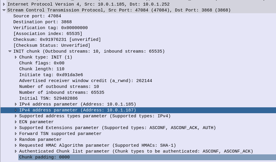
This is advertised in the INIT message, sent by the “client” to a “server” when the SCTP session is established.
SCTP INIT sent by the client at 10.0.1.185, but advertising two IPs
In the above screenshot we can see the two IPs for SCTP to use, the primary IP is the first one (10.0.1.185) and also the from IP, and there is just one additional IP (10.0.1.187) although there could be more.
In a production environment you’d want to ensure each of your IPs is in a different subnet, with different paths, hardware and routes.
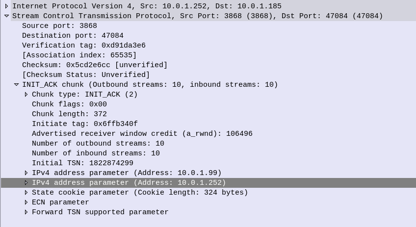
So the INIT is then responded to by the client with an INIT_ACK, and this time the server advertises it’s IP addresses, the primary IP is the From IP address (10.0.1.252) and there is just one additional IP of 10.0.1.99,
SCTP INIT ACK showing Server’s Multi-homed IP Options
Next up we have the cookie exchange, which is used to protect against synchronization attacks, and then our SCTP session is up.
So what happens at this point? How do we know if a path is up and working?
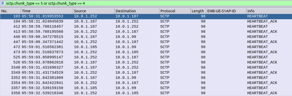
Well the answer is heartbeat messages,
Sent from each of the IPs on the client to each of the IPs on the server, to make sure that there’s a path from every IP, to every other IP.
SCTP Heartbeats from each local IP to each remote IP
This means the SCTP stacks knows if a path fails, for example if the route to IP 10.0.1.252 on the server were to fail, the SCTP stack knows it has another option, 10.0.1.99, which it’s been monitoring.
So that’s multi-homed SCTP in action – While a lot of work has historically been done with LACP for aggregating multiple NICs together, and VRRP for ensuring a host is alive, SCTP handles this in a clean and efficient way.
I’ve attached a PCAP showing multi-homing on a Diameter S6a (HSS) interface between an MME and a HSS.
So dedicated appliances are dead and all our network functions are VMs or Containers, but there’s a performance hit when going virtual as the L2 processing has to be handled by the Hypervisor before being passed onto the relevant VM / Container.
If we have a 10Gb NIC in our server, we want to achieve a 10Gbps “Line Speed” on the Network Element / VNF we’re running on.
When we talked about appliances if you purchased an P-GW with 10Gbps NIC, it was a given you could get 10Gbps through it (without DPI, etc), but when we talk about virtualized network functions / network elements there’s a very real chance you won’t achieve the “line speed” of your interfaces without some help.
When you’ve got a Network Element like a S-GW, P-GW or UPF, you want to forward packets as quickly as possible – bottlenecks here would impact the user’s achievable speeds on the network.
To speed things up there are two technologies, that if supported by your software stack and hardware, allows you to significantly increase throughput on network interfaces, DPDK & SR-IOV.
DPDK – Data Plane Development Kit
Usually *Nix OSs handle packet processing on the Kernel level. As I type this the packets being sent to this WordPress server by Firefox are being handled by the Linux 5.8.0-36-generic kernel running on my machine.
The problem is the kernel has other things to do (interrupts), meaning increased delay in processing (due to waiting for processing capability) and decreased capacity.
DPDK shunts this processing to the “user space” meaning your application (the actual magic of the VNF / Network Element) controls it.
To go back to me writing this – If Firefox and my laptop supported DPDK, then the packets wouldn’t traverse the Linux kernel at all, and Firefox would be talking directly to my NIC. (Obviously this isn’t the case…)
So DPDK increases network performance by shifting the processing of packets to the application, bypassing the kernel altogether. You are still limited by the CPU and Memory available, but with enough of each you should reach very near to line speed.
SR-IOV – Single Root Input Output Virtualization
Going back to the me writing this analogy I’m running Linux on my laptop, but let’s imagine I’m running a VM running Firefox under Linux to write this.
If that’s the case then we have an even more convolted packet processing chain!
I type the post into Firefox which sends the packets to the Linux kernel, which waits to be scheduled resources by the hypervisor, which then process the packets in the hypervisor kernel before finally making it onto the NIC.
We could add DPDK which skips some of these steps, but we’d still have the bottleneck of the hypervisor.
With PCIe passthrough we could pass the NIC directly to the VM running the Firefox browser window I’m typing this, but then we have a problem, no other VMs can access these resources.
SR-IOV provides an interface to passthrough PCIe to VMs by slicing the PCIe interface up and then passing it through.
My VM would be able to access the PCIe side of the NIC, but so would other VMs.
So that’s the short of it, SR-IOR and DPDK enable better packet forwarding speeds on VNFs.
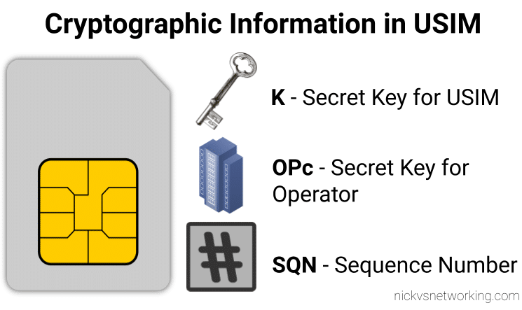
While we’ve already covered the inputs required by the authentication elements of the core network (The HSS in LTE/4G, the AuC in UMTS/3G and the AUSF in 5G) to generate an output, it’s worth noting that the Confidentiality Algorithms used in the process determines the output.
This means the Authentication Vector (Also known as an F1 and F1*) generated for a subscriber using Milenage Confidentiality Algorithms will generate a different output to that of Confidentiality Algorithms XOR or Comp128.
To put it another way – given the same input of K key, OPc Key (or OP key), SQN & RAND (Random) a run with Milenage (F1 and F1* algorithm) would yield totally different result (AUTN & XRES) to the same inputs run with a simple XOR.
Technically, as operators control the network element that generates the challenges, and the USIM that responds to them, it is an option for an operator to implement their own Confidentiality Algorithms (Beyond just Milenage or XOR) so long as it produced the same number of outputs. But rolling your own cryptographic anything is almost always a terrible idea.
So what are the differences between the Confidentiality Algorithms and which one to use? Spoiler alert, the answer is Milenage.
Milenage
Milenage is based on AES (Originally called Rijndael) and is (compared to a lot of other crypto implimentations) fairly easy to understand,
AES is very well studied and understood and unlike Comp128 variants, is open for anyone to study/analyse/break, although AES is not without shortcomings, it’s problems are at this stage, fairly well understood and mitigated.
There are a few clean open source examples of Milenage implementations, such as this C example from FreeBSD.
XOR
It took me a while to find the specifications for the XOR algorithm – it turns out XOR is available as an alternate to Milenage available on some SIM cards for testing only, and the mechanism for XOR Confidentiality Algorithm is only employed in testing scenarios, not designed for production.
Instead of using AES under the hood like Milenage, it’s just plan old XOR of the keys.
Comp128 was originally a closed source algorithm, with the maths behind it not publicly available to scrutinise. It is used in GSM A3 and A5 functions, akin to the F1 and F1* in later releases.
Due to its secretive nature it wasn’t able to be studied or analysed prior to deployment, with the idea that if you never said how your crypto worked no one would be able to break it. Spoiler alert; public weaknesses became exposed as far back as 1998, which led to Toll Fraud, SIM cloning and eventually the development of two additional variants, with the original Comp128 renamed Comp128-1, and Comp128-2 (stronger algorithm than the original addressing a few of its flaws) and Comp128-3 (Same as Comp128-2 but with a 64 bit long key generated).
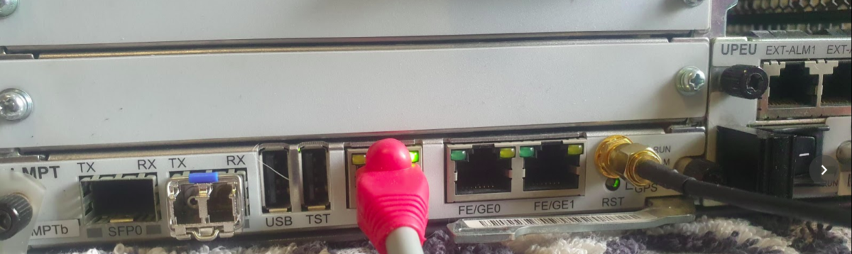
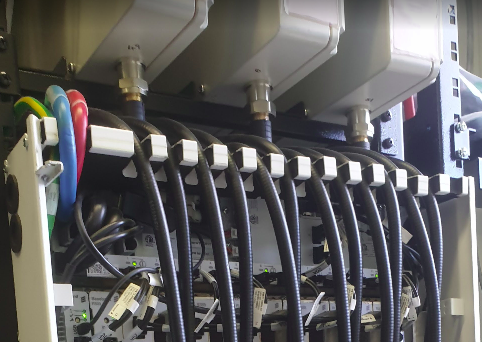
Our BTS is going to need an accurate clock source in order to run, so without access to crazy accurate Timing over Packet systems or TDM links to use as reference sources, I’ve opted to use the GPS/GLONASS receiver built into the LMPT card.
Add new GPS with ID 0 on LMPT in slot 7 of cabinet 1:
Check GPS has sync (May take some time) using the Display GPS command;
DSP GPS: GN=0;
Assuming you’ve got an antenna connected and can see the sky, after ~10 minutes running the DSP GPS:; command again should show you an output like this:
+++    4-PAL0089624        2020-11-28 01:06:55
O&M    #806355684
%%DSP GPS: GN=0;%%
RETCODE = 0  Operation succeeded.

Display GPS State
-----------------
                 GPS Clock No.  =  0
                GPS Card State  =  Normal
                 GPS Card Type  =  M12M
                 GPS Work Mode  =  GPS
                   Hold Status  =  UNHOLDED
         GPS Satellites Traced  =  4
     GLONASS Satellites Traced  =  0
         BDS Satellites Traced  =  0
Antenna Longitude(1e-6 degree)  =  144599999
 Antenna Latitude(1e-6 degree)  =  -37000000
           Antenna Altitude(m)  =  613
         Antenna Angle(degree)  =  5
             Link Active State  =  Activated
              Feeder Delay(ns)  =  15
                   GPS Version  =  NULL
(Number of results = 1)


---    END
Showing the GPS has got sync and a location fix,
Next we set BTS to use GPS as time source,
SET TIMESRC: TIMESRC=GPS;
Finally we’ll verify the Time is in sync on the BTS using the list time command:
DSP TIME:;
+++    4-PAL0089624        2020-11-28 01:09:22
O&M    #806355690
%%DSP TIME:;%%
RETCODE = 0  Operation succeeded.

Time Information
----------------
Time  =  2020-11-28 01:09:22 GMT+00:00

---    END
Optionally you may wish to add a timezone, using the SET TZ:; command, but I’ve opted to keep it in UTC for simplicity.
In our last post we covered the file system structure of a smart card and the basic concepts of communication with cards. In this post we’ll look at what happens on the application layer, and how to interact with a card.
For these examples I’ll be using SIM cards, because admit it, you’ve already got a pile sitting in a draw, and this is a telco blog after all. You won’t need the ADM keys for the cards, we’ll modify files we’ve got write access to by default.
Commands & Instructions
So to do anything useful with the card we need issue commands / instructions to the card, to tell it to do things. Instructions like select this file, read it’s contents, update the contents to something else, verify my PIN, authenticate to the network, etc.
The term Command and Instruction are used somewhat interchangeably in the spec, I realise that I’ve done the same here to make it just as confusing, but instruction means the name of the specific command to be called, and command typically means the APDU as a whole.
The “Generic Commands” section of 3GPP TS 31.101 specifies the common commands, so let’s take a look at one.
The creatively named SELECT command/instruction is used to select the file we want to work with. In the SELECT command we’ll include some parameters, like where to find the file, so some parameters are passed with the SELECT Instruction to limit the file selection to a specific area, etc, the length of the file identifier to come, and the identifier of the file.
The card responds with a Status Word, returned by the card, to indicate if it was successful. For example if we selected a file that existed and we had permission to select, we’d get back a status word indicating the card had successfully selected the file. Status Words are 2 byte responses that indicate if the instruction was successful, but also the card has data it wants to send to the terminal as a result of the instruction, how much data the terminal should expect.
So if we just run a SELECT command, telling the card to select a file, we’ll get back a successful response from the card with a data length. Next need to get that data from the card. As the card can’t initiate communication, the GET RESPONSE instruction is sent to the card to get the data from the card, along with the length of the data to be returned.
The GET RESPONSE instruction/command is answered by the card with an APDU containing the data the card has to send, and the last 2 bytes contain the Status Word indicating if it was successful or not.
APDUs
So having covered the physical and link layers, we now move onto the Application Layer – where the magic happens.
Smart card communications is strictly master-slave based when it comes to the application layer.
The terminal sends a command to the card, which in turn sends back a response. Command -> Response, Command -> Response, over and over.
These commands are contained inside APplication Data Units (APDUs).
So let’s break down a simple APDU as it appears on the wire, so to speak.
The first byte of our command APDU is taken up with a header called the class byte, abbreviated to CLA. This specifies class coding, secure messaging options and channel options.
In the next byte we specify the Instruction for the command, that’s the task / operation we want the card to perform, in the spec this is abbreviated to INS.
The next two bytes, called P1 & P2 (Parameter 1 & Parameter 2) specify the parameters of how the instruction is to be to be used.
Next comes Lc – Length of Command, which specifies the length of the command data to follow,
Datacomes next, this is instruction data of the length specified in Lc.
Finally an optional Le – Length of expected response can be added to specify how long the response from the card should be.
Crafting APDUs
So let’s encode our own APDU to send to a card, for this example we’ll create the APDU to tell the card to select the Master File (MF) – akin to moving to the root directory on a *nix OS.
For this we’ll want a copy of ETSI TS 102 221 – the catchily named “Smart cards; UICC-Terminal interface; Physical and logical characteristics” which will guide in the specifics of how to format the command, because all the commands are encoded in hexadecimal format.
So here’s the coding for a SELECT command from section 11.1.1.1 “SELECT“,
For the CLA byte in our example we’ll indicate in our header that we’re using ISO 7816-4 encoding, with nothing fancy, which is denoted by the byte A0.
For the next but we’ve got INS (Instruction) which needs to be set to the hex value for SELECT, which is represented by the hex value A4, so our second byte will have that as it’s value.
The next byte is P1, which specifies “Selection Control”, the table in the specification outlines all the possible options, but we’ll use 00 as our value, meaning we’ll “Select DF, EF or MF by file id”.
The next byte P2 specifies more selection options, we’ll use “First or only occurrence” which is represented by 00.
The Lc byte defines the length of the data (file id) we’re going to give in the subsequent bytes, we’ve got a two byte File ID so we’ll specify 2 (represented by 02).
Finally we have the Data field, where we specify the file ID we want to select, for the example we’ll select the Master File (MF) which has the file ID ‘3F00‘, so that’s the hex value we’ll use.
So let’s break this down;
Code
Meaning
Value
CLA
Class bytes – Coding options
A0 (ISO 7816-4 coding)
INS
Instruction (Command) to be called
A4 (SELECT)
P1
Parameter 1 – Selection Control (Limit search options)
00 (Select by File ID)
P2
Parameter 1 – More selection options
00 (First occurrence)
Lc
Length of Data
02 (2 bytes of data to come)
Data
File ID of the file to Select
3F00 (File ID of master file)
So that’s our APDU encoded, it’s final value will be A0 A4 00 00 02 3F00
So there we have it, a valid APDU to select the Master File.
In the next post we’ll put all this theory into practice and start interacting with a real life SIM cards using PySIM, and take a look at the APDUs with Wireshark.
The pins on the terminal / card reader are arranged so that when inserting a card, the ground contact is the first contact made with the reader, this clever design consideration to protect the card and the reader from ESD damage.
Operating Voltages
When Smart Cards were selected for use in GSM for authenticating subscribers, all smart cards operated at 5v. However as mobile phones got smaller, the operating voltage range became more limited, the amount of space inside the handset became a premium and power efficiency became imperative. The 5v supply for the SIM became a difficult voltage to provide (needing to be buck-boosted) so lower 3v operation of the cards became a requirement, these cards are referred to as “Class B” cards. This has since been pushed even further to 1.8v for “Class C” cards.
If you found a SIM from 1990 it’s not going to operate in a 1.8v phone, but it’s not going to damage the phone or the card.
The same luckily goes in reverse, a card designed for 1.8v put into a phone from 1990 will work just fine at 5v.
This is thanks to the class flag in the ATR response, which we’ll cover later on.
Clocks
As we’re sharing one I/O pin for TX and RX, clocking is important for synchronising the card and the reader. But when smart cards were initially designed the clock pin on the card also served as the clock for the micro controller it contained, as stable oscillators weren’t available in such a tiny form factor. Modern cards implement their own clock, but the clock pin is still required for synchronising the communication.
I/O Pin
The I/O pin is used for TX & RX between the terminal/phone/card reader and the Smart Card / SIM card. Having only one pin means the communications is half duplex – with the Terminal then the card taking it in turns to transmit.
Reset Pin
Resets the card’s communications with the terminal.
Filesystem
So a single smart card can run multiple applications, the “SIM” is just an application, as is USIM, ISIM and any other applications on the card.
These applications are arranged on a quasi-filesystem, with 3 types of files which can be created, read updated or deleted. (If authorised by the card.)
Because the file system is very basic, and somewhat handled like a block of contiguous storage, you often can’t expand a file – when it is created the required number of bytes are allocated to it, and no more can be added, and if you add file A, B and C, and delete file B, the space of file B won’t be available to be used until file C is deleted.
This is why if you cast your mind back to when contacts were stored on your phone’s SIM card, you could only have a finite number of contacts – because that space on the card had been allocated for contacts, and additional space can no longer be allocated for extra contacts.
So let’s take a look at our 3 file types:
MF (Master File)
The MF is like the root directory in Linux, under it contains all the files on the card.
DF (Dedciated File)
An dedicated file (DF) is essentially a folder – they’re sometimes (incorrectly) referred to as Directory Files (which would be a better name).
They contain one or more Elementary Files (see below), and can contain other DFs as well.
Dedicated Files make organising the file system cleaner and easier. DFs group all the relevant EFs together. 3GPP defines a dedicated file for Phonebook entries (DFphonebook), MBMS functions (DFtv) and 5G functions (DF5gs).
We also have ADFs – Application Dedicated Files, for specific applications, for example ADFusim contains all the EFs and DFs for USIM functionality, while ADFgsm contains all the GSM SIM functionality.
The actual difference with an ADF is that it’s not sitting below the MF, but for the level of depth we’re going into it doesn’t matter.
DFs have a name – an Application Identifier (AID) used to address them, meaning we can select them by name.
EF (Elementary File)
Elementary files are what would actually be considered a file in Linux systems.
Like in a Linux file systems EFs can have permissions, some EFs can be read by anyone, others have access control restrictions in place to limit who & what can access the contents of an EF.
There are multiple types of Elementary Files; Linear, Cyclic, Purse, Transparent and SIM files, each with their own treatment by the OS and terminal.
Most of the EFs we’ll deal with will be Transparent, meaning they ##
ATR – Answer to Reset
So before we can go about working with all our files we’ll need a mechanism so the card, and the terminal, can exchange capabilities.
There’s an old saying that the best thing about standards is that there’s so many to choose, from and yes, we’ve got multiple variants/implementations of the smart card standard, and so the card and the terminal need to agree on a standard to use before we can do anything.
This is handled in a process called Answer to Reset (ATR).
When the card is powered up, it sends it’s first suggestion for a standard to communicate over, if the terminal doesn’t want to support that, it just sends a pulse down the reset line, the card resets and comes back with a new offer.
If the card offers a standard to communicate over that the terminal does like, and does support, the terminal will send the first command to the card via the I/O line, this tells the card the protocol preferences of the terminal, and the card responds with it’s protocol preferences. After that communications can start.
Basic Principles of Smart Cards Communications
So with a single I/O line to the card, it kind of goes without saying the communications with the card is half-duplex – The card and the terminal can’t both communicate at the same time.
Instead a master-slave relationship is setup, where the smart card is sent a command and sends back a response. Command messages have a clear ending so the card knows when it can send it’s response and away we go.
Like most protocols, smart card communications is layered.
At layer 1, we have the physical layer, defining the operating voltages, encoding, etc. This is standardised in ISO/IEC 7816-3.
Above that comes our layer 2 – our Link Layer. This is also specified in ISO/IEC 7816-3, and typically operates in one of two modes – T0 or T1, with the difference between the two being one is byte-oriented the other block-oriented. For telco applications T0 is typically used.
Our top layer (layer 7) is the application layer. We’ll cover the details of this in the next post, but it carries application data units to and from the card in the form of commands from the terminal, and responses from the card.
Coming up Next…
In the next post we’ll look into application layer communications with cards, the commands and the responses.
I know a little bit about SIM cards / USIM cards / ISIM Cards. Enough to know I don’t know very much about them at all.
So throughout this series of posts of unknown length, I’ll try and learn more and share what I’m learning, citing references as much as possible.
So where to begin? I guess at the start,
A supposedly brief history of Smart Cards
There are two main industries that have driven the development and evolution of smart cards – telecom & banking / finance, both initially focused on the idea that carrying cash around is unseemly.
This planet has – or rather had – a problem, which was this: most of the people living on it were unhappy for pretty much of the time. Many solutions were suggested for this problem, but most of these were largely concerned with the movement of small green pieces of paper, which was odd because on the whole it wasn’t the small green pieces of paper that were unhappy.
Douglas Adams – The Hitchhiker’s Guide to the Galaxy
When the idea of Credit / Debit Cards were first introduced the tech was not electronic, embossed letters on the card were fed through that clicky-clacky-transfer machine (Google tells me this was actually called the “credit card imprinter”) and the card details imprinted onto carbon copy paper.
Customers wanted something faster, so banks delivered magnetic strip cards, where the card data could be read even more quickly, but as the security conscious of you will be aware, storing data on magnetic strips on a card to be read by any reader, allows them to be read by any reader, and therefore duplicated really easily, something the banks quickly realised.
To combat this, card readers typically would have a way to communicate back to a central bank computer. The central computer verified the PIN entered by the customer was correct, confirmed that the customer had enough money in their balance for the transaction and it wasn’t too suspicious. This was, as you would imagine in the late 1980’s early 1990’s, rather difficult to achieve. A reliable (and cheap) connection back to a central bank computer wasn’t always a given, nor instant, and so this was still very much open to misuse.
“Carders” emmerged, buying/selling/capturing credit card details, and after programming a blank card with someone else’s fraudulently obtained card details, could write them on a blank card before going on a spending spree for a brief period of time. Racking up a giant debt that wasn’t reconciled against the central computer until later, when the card was thrown away and replaced with another.
I know what you’re thinking – I come to this blog for ramblings about Telecommunications, not the history of the banking sector. So let’s get onto telco;
The telecom sector faced similar issues, at the time mobile phones were in their infancy, and so Payphones were how people made calls when out and about.
A phone call from a payphone in Australia has sat at about $0.40 for a long time, not a huge amount, but enough you’d always want to be carrying some change if you wanted to make calls. Again, an inconvenience for customers as coins are clunky, and an inconvenience for operators as collecting the coins from tens of thousands of payphones is expensive.
Telcos around the world trailed solutions, including cards with magnetic strips containing the balance of the card, but again people quickly realised that you could record the contents of the magnetic stripe data of the card when it had a full balance, use all the balance on the card, and then write back the data you stored earlier with a full balance.
So two industries each facing the same issue: it’s hard to securely process payments offline in a way that can’t be abused.
Enter the smart card – a tiny computer in a card that the terminal (Payphone or Credit Card Reader) interacts with, but the card is very much in charge.
When used in a payphone, the caller inserts the smart card and dials the number, and dialog goes something like this (We’ll assume Meter Pulses are 40c worth):
Payphone: “Hey SmartCard, how much credit do you have on you?”
Smart Card: “I have $1.60 balance”
*Payphone ensures card has enough credit for the first meter pulse, and begins listening for Meter Pulses*
*When a meter pulse received:*
Payphone: “Please deduct $0.40 from your Balance”
Smart Card: “Ok, you have $1.20 remaining”
This process repeats for each meter pulse (Payphone metering is a discussion for another day) until all the credit has been used / Balance is less than 1 meter pulse charge.
While anyone could ask the smart card “Hey SmartCard, how much credit do you have on you?” it would only return the balance, and if you told the smart card “I used $1 credit, please deduct it” like the payphone did, you’d just take a dollar off the credit stored on the card.
Saying “Hey SmartCard set the balance to $1,000,000” would result in a raised eyebrow from the SmartCard who rejects the request.
After all – It’s a smart card. It has the capability to do that.
So in the telecom sector single use smart cards were rolled out, programmed in the factory with a set dollar value of credit, sold at that dollar value and thrown away when depleted.
The banking industry saw even more potential, balance could be stored on the card, and the PIN could be verified by the card, the user needs to know the correct PIN, as does the smart card, but the terminal doesn’t need to know this, nor does it need to talk back to a central bank computer all the time, just every so often so the user gets the bill.
It worked much the same way, although before allowing a deduction to be made from the balance of the card, a user would have to enter their PIN which was verified by the card before allowing the transaction.
Eventually these worlds collided (sort of), both wanting much the same thing from smart cards. So the physical characteristics, interface specs (rough ones) and basic communications protocol was agreed on, and what eventually became ISO/IEC 7816 was settled upon.
Any card could be read by any terminal, and it was up to the systems implementer (banks and telecos initially) what data the card did and what the terminal did.
Active RFID entered the scene and there wasn’t even a need for a physical connection to the card, but the interaction was the same. We won’t really touch on the RFID side, but all of this goes for most active RFID cards too.
Enter Software
Now the card was a defined standard all that was important really was the software on the card. Banks installed bank card software on their cards, while telcos installed payphone card software on theirs.
But soon other uses emerged, ID cards could provide a verifiable and (reasonably) secure way to verify the card’s legitimacy, public transport systems could store commuter’s fares on the card, and vending machines, time card clocks & medical records could all jump on the bandwagon.
These were all just software built on the smart card platform.
Hello SIM Cards
A early version Smart card was used in the German C-Netz cellular network, which worked in “mobile” phones and also payphones, to authenticate subscribers.
After that the first SIM cards came into the public sphere in 1991 with GSM as a way to allow a subscriber’s subscription to be portable between devices, and this was standardised by ETSI to become the SIM cards still used in networks using GSM, and evolved into the USIM used in 3G/4G/5G networks.
Names of Smart Cards & Readers
To make life a bit easier I thought I’d collate all the names for smart cards and readers that are kind of different but used interchangeably depending on the context.
Smart Card
|
Terminal
UICC (Universal Integrated Circuit Card) – Standards name for Smart Card
Card Reader (Generic)
SIM (Mobile Telco application running on UICC)
Phone (Telco)
USIM (Mobile Telco application running on UICC)
SIM Slot (Telco)
Credit / Debit / EFTPOS Card (Banking)
UE (Telco)
Java Card (Type of Smart Card OS)
EFTPOS Terminal (Banking)
Phone Card (Telco / Payphone)
And then…
From here we’ll look at various topics:
Introduction to Smart Cards (This post)
Meet & Greet (The basics of Smart Cards & their File System)
APDUs and Hello Card (How terminals interact with a smart cards)
(Interacting with real life cards using Smart Card readers and SIM cards)
Mixing It Up (Changing values on Cards)
Other topics we may cover are Javacard and Global Platform, creating your own smart card applications, a deeper look at the different Telco apps like SIM/USIM/ISIM, OTA Updates for cards / Remote File Management (RFM), and developing for SimToolkit.
Recently I’ve been wrapping my head around Cell Broadcast in LTE, and thought I’d share my notes on 3GPP TS 38.413.
The interface between the MME and the Cell Broadcast Center (CBC) is the SBc interface, which as two types of “Elementary Procedures”:
Class 1 Procedures are of the request – response nature (Request followed by a Success or Failure response)
Class 2 Procedures do not get a response, and are informational one-way. (Acked by SCTP but not an additional SBc message).
SCTP is used as the transport layer, with the CBC establishing a point to point connection to the MME over SCTP (Unicast only) on port 29168 with SCTP Payload Protocol Identifier 24.
The SCTP associations between the MME and the CBC should normally remain up – meaning the SCTP association / transport connection is up all the time, and not just brought up when needed.
Elementary Procedures
Write-Replace Warning (Class 1 Procedure)
The purpose of Write-Replace Warning procedure is to start, overwrite the broadcasting of warning message, as defined in 3GPP TS 23.041 [14].
Write-Replace Warning procedure, initiated by WRITE-REPLACE WARNING REQUEST sent by the CBC to the MMEs contains the emergency message to be broadcast and the parameters such as TAC to broadcast to, severity level, etc.
A WRITE-REPLACE WARNING RESPONSE is sent back by the MME to the MME, if successful, along with information as to where it was sent out. CBC messages are unacknowledged by UEs, meaning it’s not possible to confirm if a UE has actually received the message.
The request includes the message identifier and serial number, list of TAIs, repetition period, number of broadcasts requested, warning type, and of course, the warning message contents.
Stop Warning Procedure (Class 1 Procedure)
Stop Warning Procedure, initiated by STOP WARNING REQUEST and answered with a STOP WARNING RESPONSE, requests the MME inform the eNodeBs to stop broadcasting the CBC in their SIBs.
Includes TAIs of cells this should apply to and the message identifier,
Error Indication (Class 2)
The ERROR INDICATION is used to indicate an error (duh). Contains a Cause and Criticality IEs and can be sent by the MME or CBC.
Write Replace Warning (Class 2)
The WRITE REPLACE WARNING INDICATION is used to indicate warning scenarios for some instead of a WRITE-REPLACE WARNING RESPONSE,
PWS Restart (Class 2)
The PWS RESTART INDICATION is used to list the eNodeBs / cells, that have become available or have restarted, since the CBC message and have no warning message data – for example eNodeBs that have just come back online during the period when all the other cells are sending Cell Broadcast messages.
Returns a the Restarted-Cell-List IE, containing the Global eNB ID IE and List of TAI, of the restarted / reconnected cells.
PWS Failure Indication (Class 2)
The PWS FAILURE INDICATION is essentially the reverse of PWS RESTART INDICATION, indicating which eNodeBs are no longer available. These cells may continue to send Cell Broadcast messages as the MME has essentially not been able to tell it to stop.
Contains a list of Failed cells (eNodeBs) with the Global-eNodeB-ID of each.