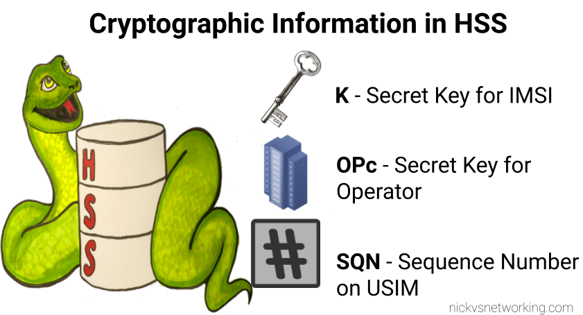
I’ve written about Milenage and SIM based security in the past on this blog, and the component that prevents replay attacks in cellular network authentication is the Sequence Number (Aka SQN) stored on the SIM.
Think of the SQN as an incrementing odometer of authentication vectors. Odometers can go forward, but never backwards. So if a challenge comes in with an SQN behind the odometer (a lower number), it’s no good.
Why the SQN is important for Milenage Security
Every time the SIM authenticates it ticks up the SQN value, and when authenticating it checks the challenge from the network doesn’t have an SQN that’s behind (lower than) the SQN on the SIM.
Let’s take a practical example of this:
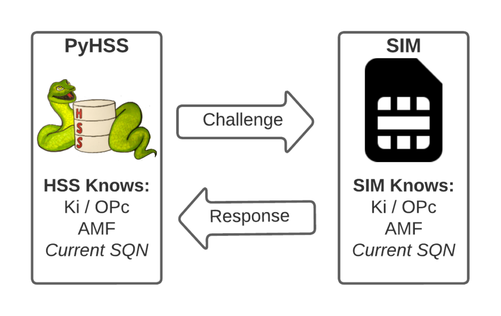
The HSS in the network has SQN for the SIM as 8232, and generates an authentication challenge vector for the SIM which includes the SQN of 8232.
The SIM receives this challenge, and makes sure that the SQN in the SIM, is equal to or less than 8232.
If the authentication passes, the new SQN stored in the SIM is equal to 8232 + 1, as that’s the next valid SQN we’d be expecting, and the HSS incriments the counters it has in the same way.
By constantly increasing the SQN and not allowing it to go backwards, means that even if we pre-generated a valid authentication vector for the SIM, it’d only be valid for as long as the SQN hasn’t been authenticated on the SIM by another authentication request.
Imagine for example that I get sneaky access to an operator’s HSS/AuC, I could get it to generate a stack of authentication challenges that I could use for my nefarious moustache-twirling purposes whenever I wanted.
This attack would work, but this all comes crumbling down if the SIM was to attach to the real network after I’ve generated my stack of authentication challenges.
If the SQN on the SIM passes where it was when the vectors were generated, those vectors would become unusable.
It’s worth pointing out, that it’s not just evil purposes that lead your SQN to get out of Sync; this happens when you’ve got subscriber data split across multiple HSSes for example, and there’s a mechanism to securely catch the HSS’s SQN counter up with the SQN counter in the SIM, without exposing any secrets, but it just ticks the HSS’s SQN up – It never rolls back the SQN in the SIM.
The Flaw – Draining the Pool
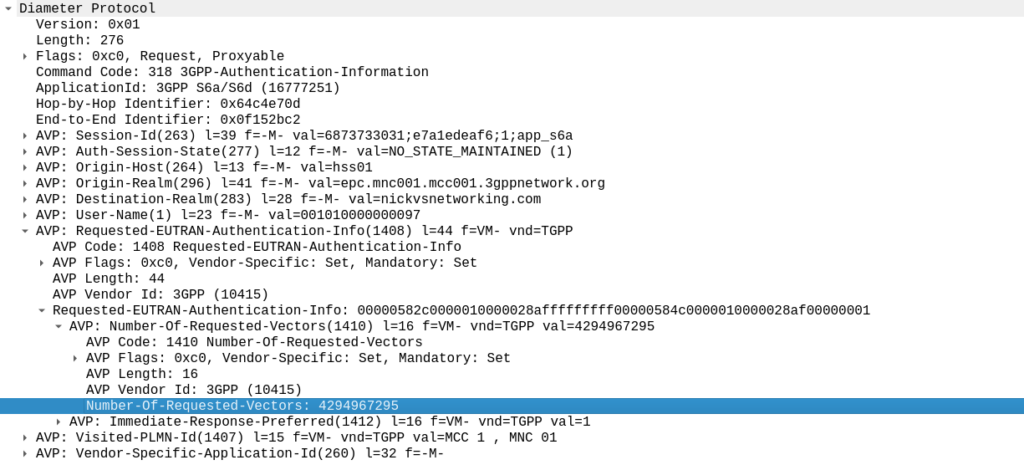
The Authentication Information Request is used by a cellular network to authenticate a subscriber, and the Authentication Information Answer is sent back by the HSS containing the challenges (vectors).
When we send this request, we can specify how many authentication challenges (vectors) we want the HSS to generate for us, so how many vectors can you generate?
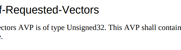
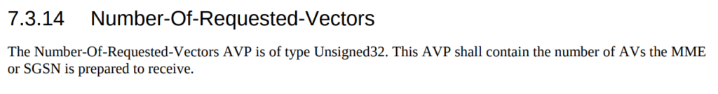
TS 129 272 says the Number-of-Requested-Vectors AVP is an Unsigned32, which gives us a possible pool of 4,294,967,295 combinations. This means it would be legal / valid to send an Authentication Information Request asking for 4.2 billion vectors.
It’s worth noting that that won’t give us the whole pool.
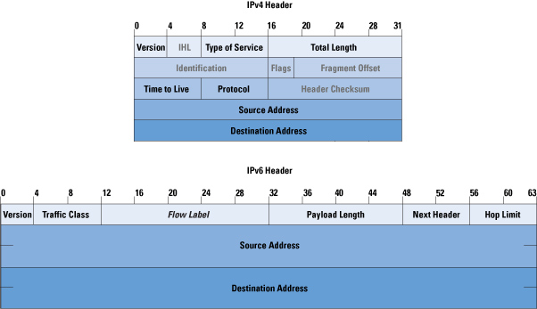
Sequence numbers (SQN) shall have a length of 48 bits.
TS 133 102
While the SQN in the SIM is 48 bits, that gives us a maximum number of values before we “tick over” the odometer of 281,474,976,710,656.
If we were to send 65,536 Authentication-Information-Requests asking for 4,294,967,295 a piece, we’d have got enough vectors to serve the sub for life.
Except the standard allows for an unlimited number of vectors to be requested, this would allow us to “drain the pool” from an HSS to allow every combination of SQN to be captured, to provide a high degree of certainty that the SQN provided to a SIM is far enough ahead of the current SQN that the SIM does not reject the challenges.
Can we do this?
Our lab has access to HSSes from several major vendors of HSS.
Out of the gate, the Oracle HSS does not allow more than 32 vectors to be requested at the same time, so props to them, but the same is not true of the others, all from major HSS vendors (I won’t name them publicly here).
For the other 3 HSSes we tried from big vendors, all eventually timed out when asking for 4.2 billion vectors (don’t know why that would be *shrug*) from these HSSes, it didn’t get rejected.
This is a lab so monitoring isn’t great but I did see a CPU spike on at least one of the HSSes which suggests maybe it was actually trying to generate this.
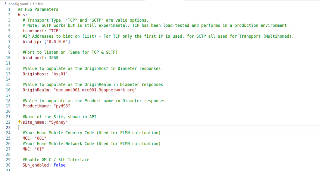
Of course, we’ve got PyHSS, the greatest open source HSS out there, and how did this handle the request?
Well, being standards compliant, it did what it was asked – I tested with 1024 vectors I’ll admit, on my little laptop it did take a while. But lo, it worked, spewing forth 1024 vectors to use.
So with that working, I tried with 4,294,967,295…
And I waited. And waited.
And after pegging my CPU for a good while, I had to get back to real life work, and killed the request on the HSS.
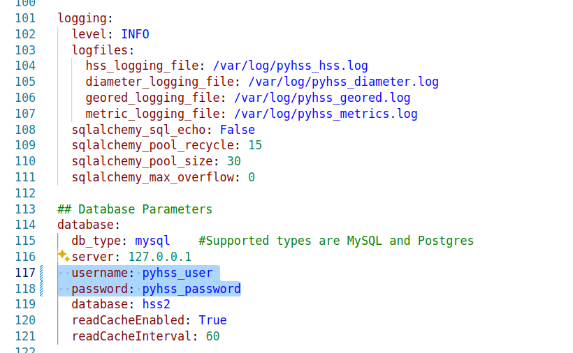
In part there’s the fact that PyHSS writes back to a database for each time the SQN is incremented, which is costly in terms of resources, but also that generating Milenage vectors in LTE is doing some pretty heavy cryptographic lifting.
The Risk
Dumping a complete set of vectors with every possible SQN would allow an attacker to spoof base stations, and the subscriber would attach without issue.
Historically this has been very difficult to do for LTE, due to the mutual network authentication, however this would be bypassed in this scenario.
The UE would try for a resync if the SQN is too far forward, which mitigates this somewhat.
Cryptographically, I don’t know enough about the Milenage auth to know if a complete set of possible vectors would widen the attack surface to try and learn something about the keys.
Mitigations / Protections
So how can operators protect ourselves against this kind of attack?
Different commercial HSS vendors handle this differently, Oracle limits this to 32 vectors, and that’s what I’ve updated PyHSS to do, but another big HSS vendor (who I won’t publicly shame) accepts the full 4294967295 vectors, and it crashes that thread, or at least times it out after a period.
If you’ve got a decent Diameter Routing Agent in place you can set your DRA to check to see if someone is using this exploit against your network, and to rewrite the number of requested vectors to a lower number, alert you, or drop the request entirely.
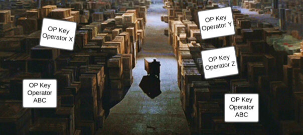
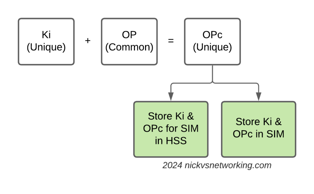
Having common OP keys is dumb, and I advocate to all our operator customers to use OP keys that are unique to each SIM, and use the OPc key derived anyway. This means if one SIM spilled it’s keys, the blast doesn’t extend beyond that card.
In the long term, it’d be good to see 3GPP limit the practical size of the Number-of-Requested-Vectors AVP.
2G/3G Impact
Full disclosure – I don’t really work with 2G/3G stacks much these days, and have not tested this.
MAP is generally pretty bandwidth constrained, and to transfer 280 billion vectors might raise some eyebrows, burn out some STPs and take a long time…
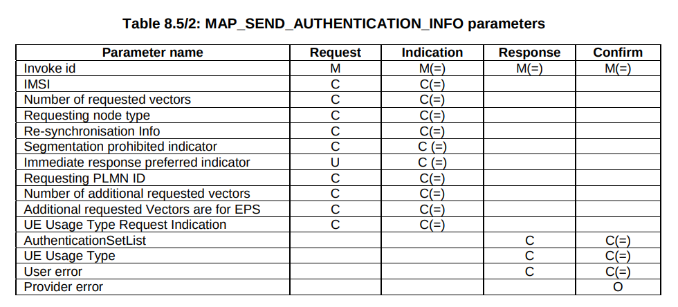
But our “Send Authentication Info” message functions much the same as the Authentication Information Request in Diameter, 3GPP TS 29.002 shows we can set the number of vectors we want:
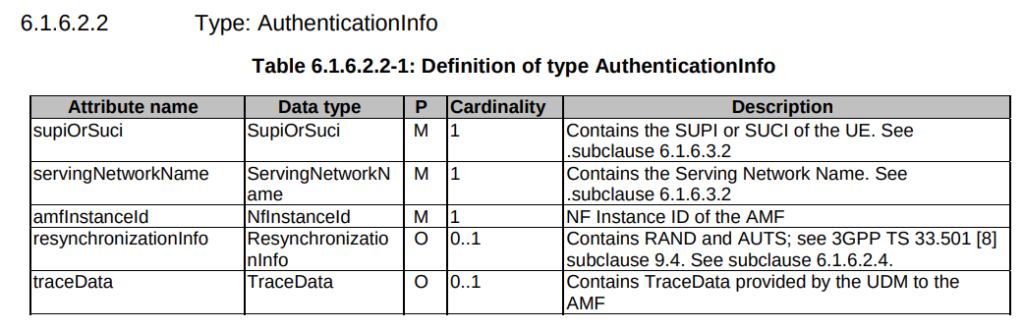
5GC Vulnerability
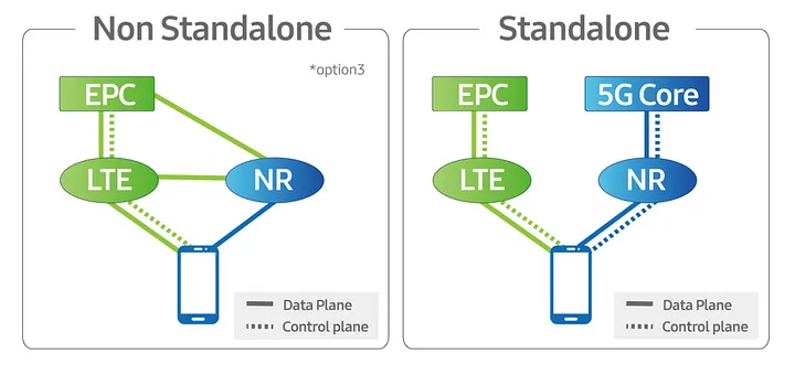
This only impacts LTE and 5G NSA subscribers.
TS 29.509 outlines the schema for the Nausf reference point, used for requesting vectors, and there is no option to request multiple vectors.
Summary
If you’ve got baddies with access to your HSS / HLR, you’ve got some problems.
But, with enough time, your pool could get drained for one subscriber at a time.
This isn’t going to get the master OP Key or plaintext Ki values, but this could potentially weaken the Milenage security of your system.