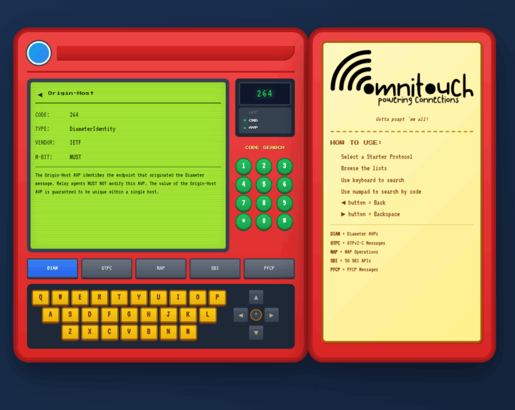
I do a lot of protocol testing, writing Diameter/PFCP/GTP-C etc, and spend a lot of time referencing the standards.
So I built this – Inspired by a 1990s video game / TV / Playing card franchise online reference tool, but rather than identifying pocket monsters, it’s identifying AVPs and stuff
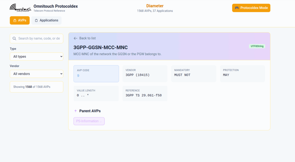
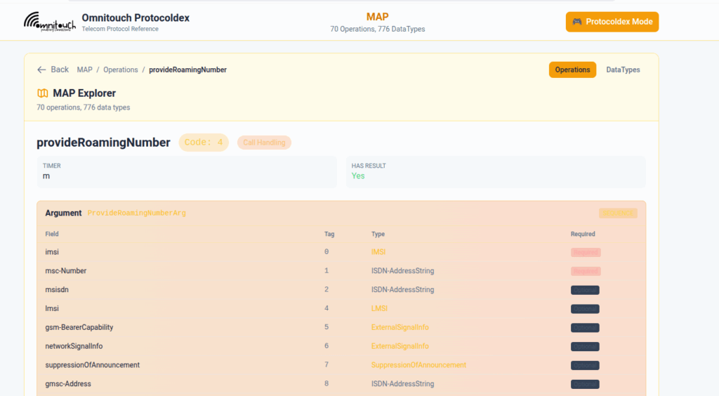
You can punch in the AVP code, AVP name, description, etc, for Diameter, PFCP, GTP-C, MAP or SBI and see all the details to go with it.
I’ve been using it a heap, hopefully some of you might find it useful:
One of our customers is an MVNE and they reached out the other day with an issue.
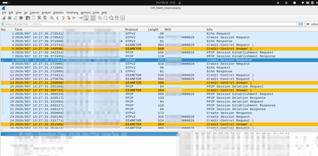
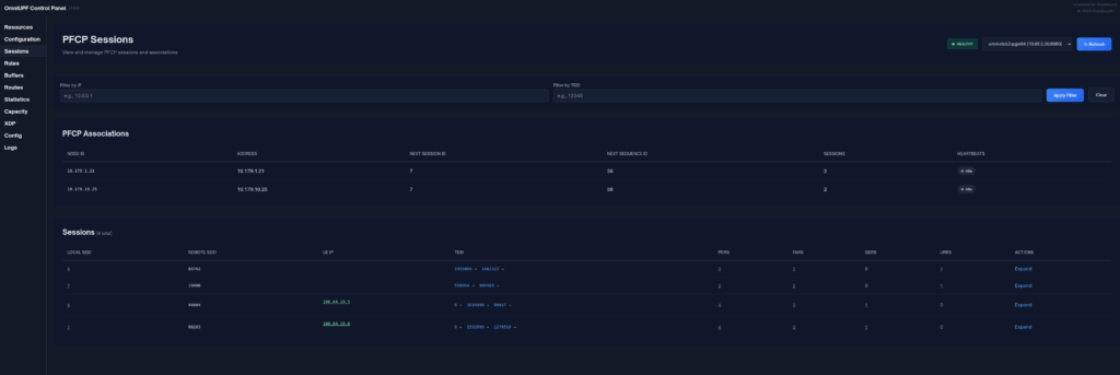
They were turning up a new PGW and they’d see Create Session Request, everything looked OK, it’d get a response, but then in the GUI of the PGW-C they’d see the session drop.
The logs showed the newly setup session dropping shortly after being setup.
Have a look at the screenshot and see if you can work out why:
So what’s going on, and why is the PGW-C deleting sessions?
The initial reaction from the customer was there’s something up with the PGW, but the answer is bit more nuanced.
Per the specs, you can’t have two PDN sessions for the same subscriber (IMSI) on the same APN (DNN).
So if 50557000000001 is connected to the PGW-C on the internet APN, if I send another Create Session Request to the same PGW-C, it deletes the old session, before starting the new one.
In this case, the MVNE it was going through was dropping the Create Session Response, so it never made it back to the MNO, and then the MME in the MNO sent it again.
Joys of GTPv2-C being UDP based and connectionless!
Over a decade ago, Dan McKinley published a blog post titled “Choose Boring Technology” which advocates that software developers and engineers design systems using “boring” technology.
One of the most worthwhile exercises I recommend here is to consider how you would solve your immediate problem without adding anything new. First, posing this question should detect the situation where the “problem” is that someone really wants to use the technology. If that is the case, you should immediately abort.
In the long time since he wrote that post, I feel like a lot of the tech industry has matured in it’s approach and learned these lessons – We’re not jumping onto the bleeding edge new-fangled tools as much, and instead developers and engineers are sticking towards tried and tested design patterns in order to achieve the business goals.
No Hayden, this doesn’t mean I’ll write PHP.
But it feels like in telecom at least, leadership teams have not learned this lesson.
Every telco conference I go to I hear about “telco to tech co transformation” in presentations from telecom CTOs on the verge of retirement, and it’s bullshit.
We are a boring tool – Telecom is the boring technology.
Boring it may be, but customers have only shown a demand for connectivity from telecom operators.
End customers aren’t showing demand for TV content from their operators (sports rights anyone?), bundled services, AI something, metaverse, connected cars, crypto, 5G slicing, containers, edge, robotic surgery or whatever else is being shilled as the next best thing for telecom operators.
The idea of diversifying into other revenue streams fails to ask the question of why telcos would be better suited to deliver value in those markets than literally every other organization on the planet. In the majority of cases, there’s no strong case to be made for telcos to take the lead here. Telecom projects generally have a much higher failure rate than that of most other sectors in tech, so why would telcos be best suited to these new industries?
Customers have consistently shown demand for fast, reliable, affordable access to connectivity, and only that. That’s what customers want from us as an industry – We should have a laser like focus on delivering that, better and better year on year, and not chasing distractions.
As an example, go to Google Maps reviews, or Down Detector and find the feedback from customers of any given telco. While telcos crow about NPS the lived experience of customers – justified or not, is often pretty piss poor.
Chasing becoming a tech-co distracts from the core business for a network operator, of, well, operating the network.
Any talk of “business transformation” and shifting to becoming a tech-co just distracts from that mission.
We’re largely utilities and we’re not sexy, but that’s okay.
We all know Bell Labs, Australia’s Telecom labs and others produced some amazing technology inventions and were at the forefront of tech in their day – Shockley, Shannon, etc. But that was finished by the 1970s, and required a state monopoly and with an R&D budget that rivaled that of many small countries. That monopoly is gone, and that money is gone. We can’t compete on broad tech innovation.
But consistently, since the telephone was first introduced in the 1800s, communications has been what customers want.
What we do isn’t shiny, but it is critical, and there’s still plenty of room for improvement in our space, to do things better. I hope we as an industry focus on just doing what we do now but better, and embrace being a boring technology.
When a UE enters Idle mode, the network releases radio resources and the UE enters power saving mode.
When the UE wants to send data (Uplink) the UE just tells the network “hey I want to send something” and away it goes, nice and simple.
But when the network wants to send data to the UE (Downlink) then the UPF needs a method to tell the Control Plane (SGW-C or SMF) that there’s data waiting and to go and page the UE.
A prime example of this is when you’ve got a Mobile Terminated VoLTE call coming in, you need a way to tell the UE to wake up out of Idle mode because you’ve got something to send to it (a SIP INVITE).
But in order for this to work, we can’t just say “Hey I’ve got some packets for you” and let them get dropped, the UPF also needs to buffer (store temporarily) the downlink packets for the UE until the UE comes out of Idle mode, and then flush them out to deliver them to the UE.
So let’s look at the flow.
Enabling Buffering (Idle Mode)
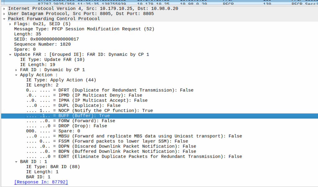
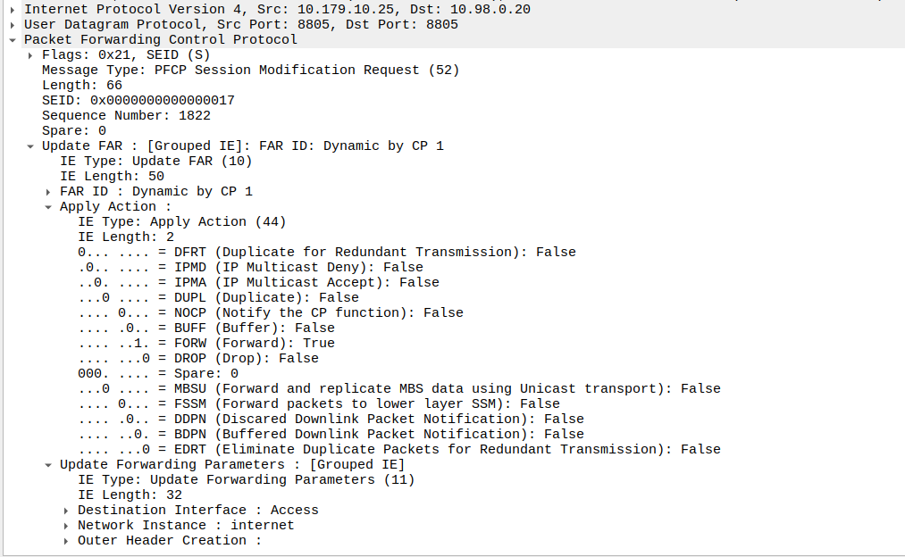
When the sub enters idle mode, the Control Plane (SGW-C for an EPC or SMF for a 5GC) it sends a Session Modification Request but with the BUFF (Buffer) and NOCP (Notify Control Plane) flags set, and FORW (Forward) turned off.
What this means is now for packets to that bearer, the UPF must:
Not forward any traffic
Buffer the traffic
Notify the control plane when the first packet comes in that we buffer
Then the UPF just sits and waits for any incoming packets.
The Notify
When the UE gets an incoming packet that it’s supposed to buffer and notify, well, it does just that.
The packets are copied into a buffer, in sequence, and for the first packet, the UPF must send a notification to the Control Plane.
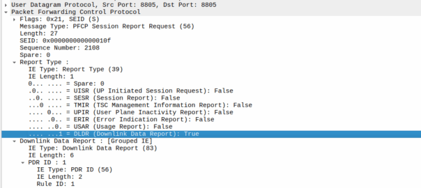
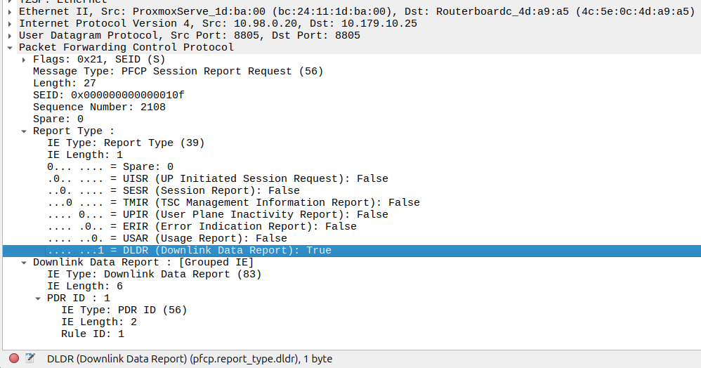
That looks like this, it’s just a Session Report Request with the Dowlink Data Report flag.
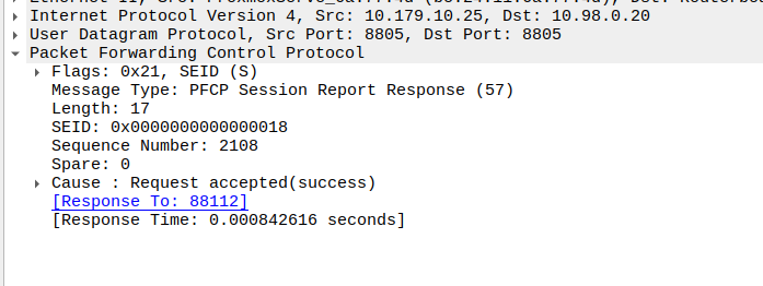
Now the SMF/SGW-U sends back a Session Report Response and starts the process of paging the UE.
At the same time the UPF keeps buffering – It’s work is not done.
Flushing and Forwarding
Once the UE has become reachable, the Control Panel needs to modify the bearer to turn back on forwarding. It does through another Session Modification Request, this is the inverse of the one it sent to turn on buffering, as we’re turning off buffering and notifications, and turning on forwarding.
Now the UPF flushes it’s buffer – It’ll send all the packets that were queued up out over the wire towards the gNB / eNodeB, so the SIP INVITE for the MT call or whatever will make it through.
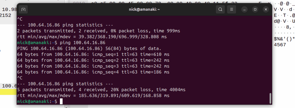
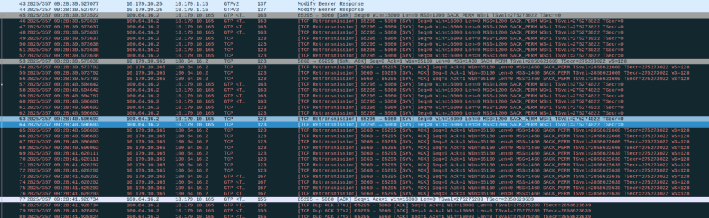
One thing to note is that the packets that get buffered are going to take some time to get delivered, as the NOTIFY / page UE / reconnect UE / Session Modification Request (to enable forwarding again) needs to happen before the buffers are flushed and delivered.
Notice the latency spike on the first packet? 610ms? That’s because the UE had to be paged to wake up.
And that’s pretty much it, the UPF has now flushed it’s buffers and moves back to forwarding actions.
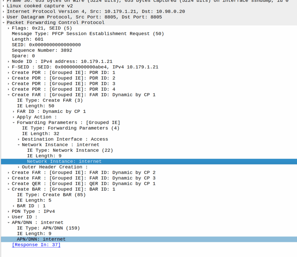
I was recently looking for a field I could use in PFCP to denote the VRF / Network Segment to be used, and initially thought Network Instance would be perfect for this.
It’s not.
Network Instance is kinda preferred over the APN/DNN for decisions, for example a Packet Detection Rule (PDR) does not give a damn what you’ve set as the APN/DNN, only what the Network Instance is set to:
a combination of the parameters, that incoming packets are requested to match, among: Local F-TEID, Network Instance, UE IP address(es), SDF Filter(s) and/or Application ID. For 5GC, the PDI may additionally contain one or more QFI(s) to detect traffic pertaining to specific QoS flow(s), Ethernet Packet Filter(s) and/or Ethernet PDU Session Information (see clause 5.13.1).
Our team recently shipped a new UPF which is a huge improvement on our old UPF, and I drew the short straw of doing all the interop testing for the IMS.
Initially I thought there was an issue with IP routing, as I’d never see the SIP register from the UE, but I would see the IMS APN coming up.
I could access the internet from the UE IPs just fine, but that’s going to public IPs, whereas the P-CSCF is in private address space, and hosted on the same box as the UPF.
I spent hours on this as my lab servers do routing on a stick, and I thought some hardware offload somewhere was trying to fast path my packets and send them back to the server without going via the router.
Then I dug a little deeper and found I could see the 3 way handhake between the UE an the P-CSCF, but no SIP packets.
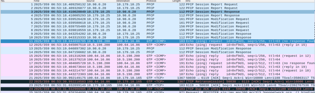
Successful 3 way handshake between the UE and the P-CSCF on TCP 5060
This was confusing, clearly we had at least intermittent two way comms – the 3 way TCP handshake confirmed that, but then why were packets not getting across?
We have an XCAP server hosted on our P-CSCF instances, so I tried hitting that from the phone in case there was something weird about routing to the network segment that hosts the P-CSCF, but I could hit the XCAP server just fine, so now I was certain the UE IP pool could route to the P-CSCF and 3 way handshake for TCP was working and payload could be pushed.
Clearly we can route to the P-CSCF as that’s where this XCAP server is hosted
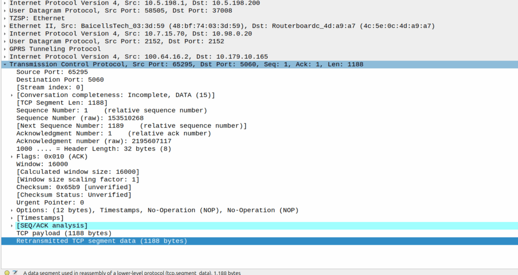
Then I dug into what happened after the 3 way handshake, and I found a TCP payload containing the start of the SIP REGISTER.
Hmm, we have a SIP Fragment here at least…
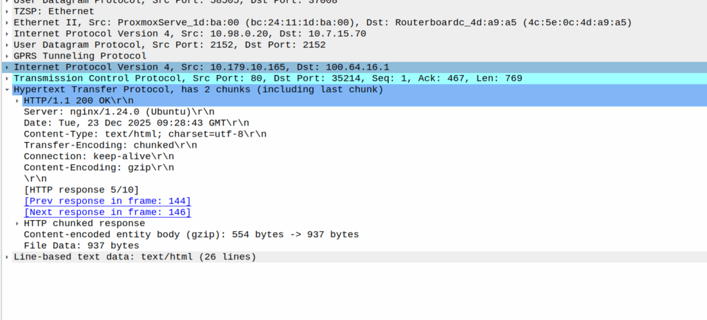
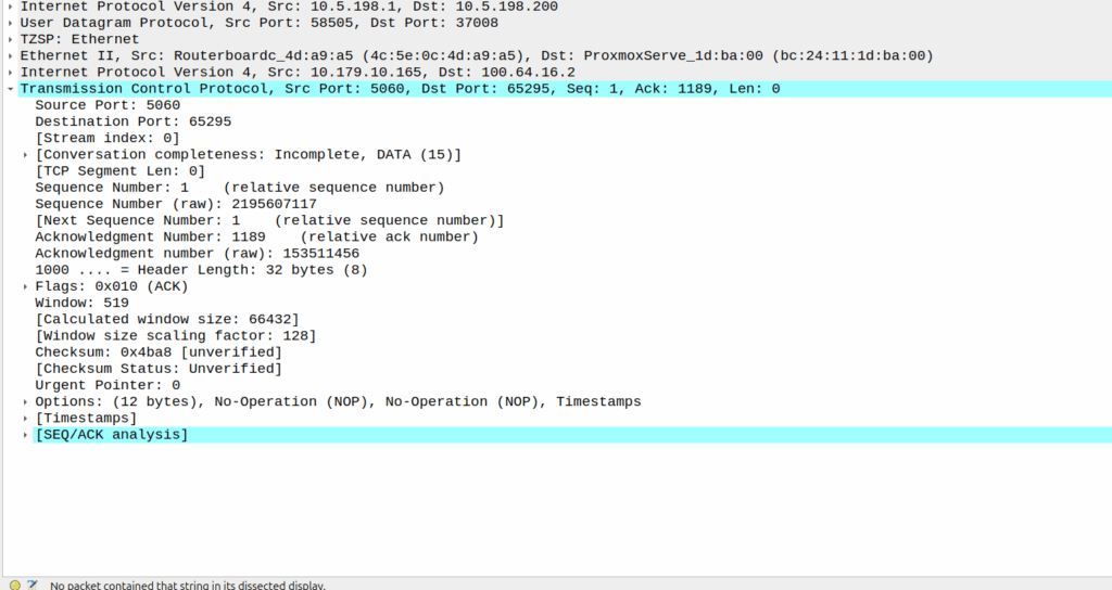
I traced it all the way through and lo, it’s hitting the P-CSCF:
And the fragment is recieved on the P-CSCF
Okay, but then what happens, because it’s only a fragment, not the complete re-assembled packet, so what’s going on?
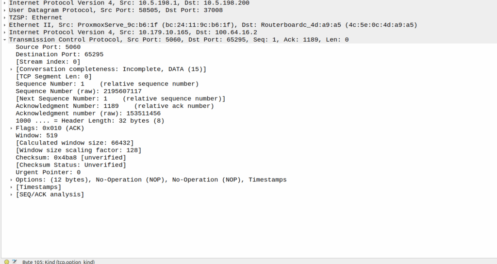
Well, the P-CSCF sends a TCP ACK back to the UE.
And the TCP fragment containing the first part of the REGISTER gets an ACK back from the P-CSCF
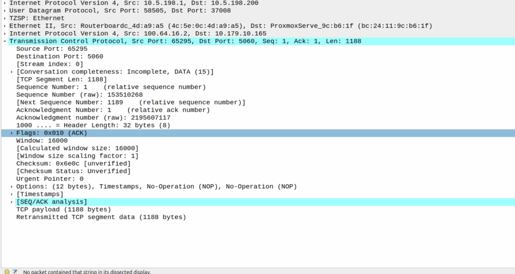
The ACK gets forwarded to the UPF:
And that TCP ack makes it to the P-CSCF
And then… Nothing? The UPF never encaps the TCP ACK back into GTP-U and never sends it onto base station.
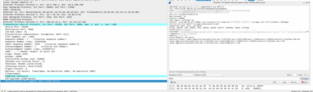
Eventually the UE re-sends the payload with the start of the REGISTER, but it does not get the ACK from the P-CSCF.
Retransmitted TCP segment containing the REGISTER from the UE
So naughty UPF right? Not forwarding that ACK for some reason?
I started digging, maybe the ACK was getting routed weirdly and landing on the UPF without going through the router?
Well not quite…
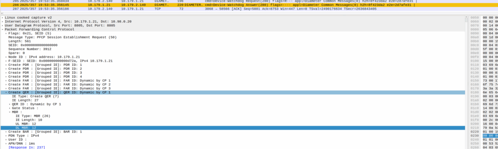
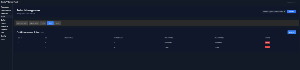
When I started digging into the QER rules being installed I noticed the MBR bitrate we had on the IMS APN in the HSS was tiny.
The UPF can only gate on traffic to the UE, so was gating the ACK traffic, as the QER had consumed all the bandwidth so the ACK never made it back.
Time wasted – About 4 hours, but I will not make this mistake again!
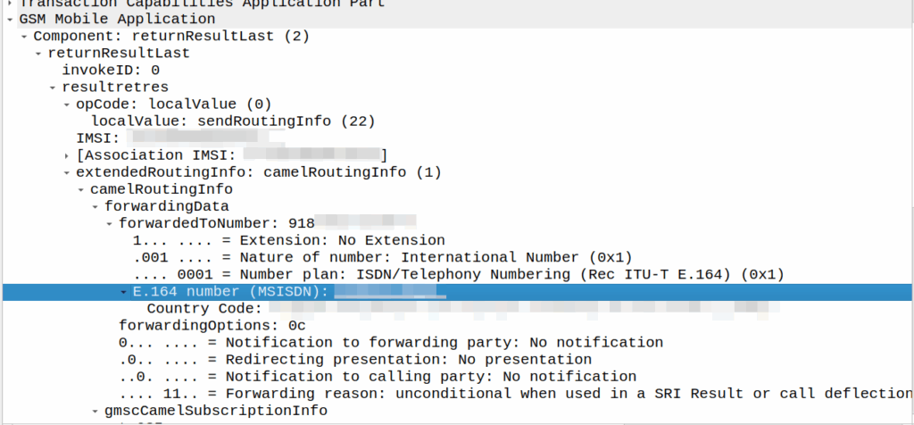
I’ve covered how SS7/ISUP handles call forward before, but the HLR can also store call forwarding information.
This is returned to the MSC when the SendRoutingInfo dialog is performed against the HLR.
If it’s present the MSC will redirect the call to that destination, after bouncing it through CAMEL (if enabled).
A lot simpler than Call Forward in IMS, but same outcome.
A lot of HSSes we see are just HLRs under the hood and only implement a minimalist MMTel feature set for call forwarding for this reason to have it track across both.
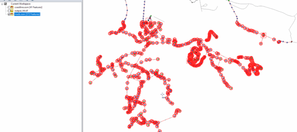
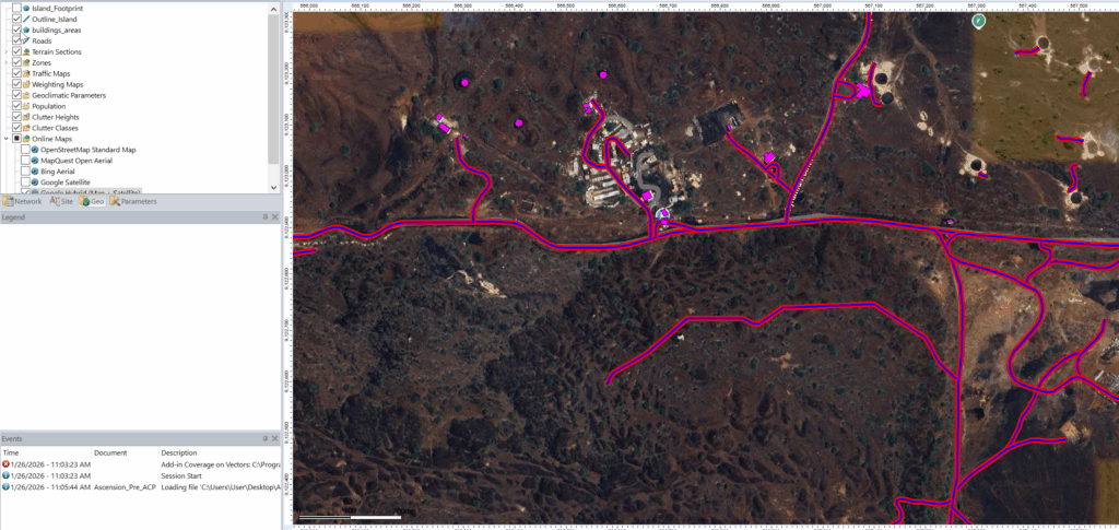
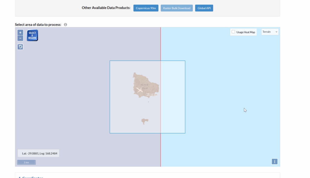
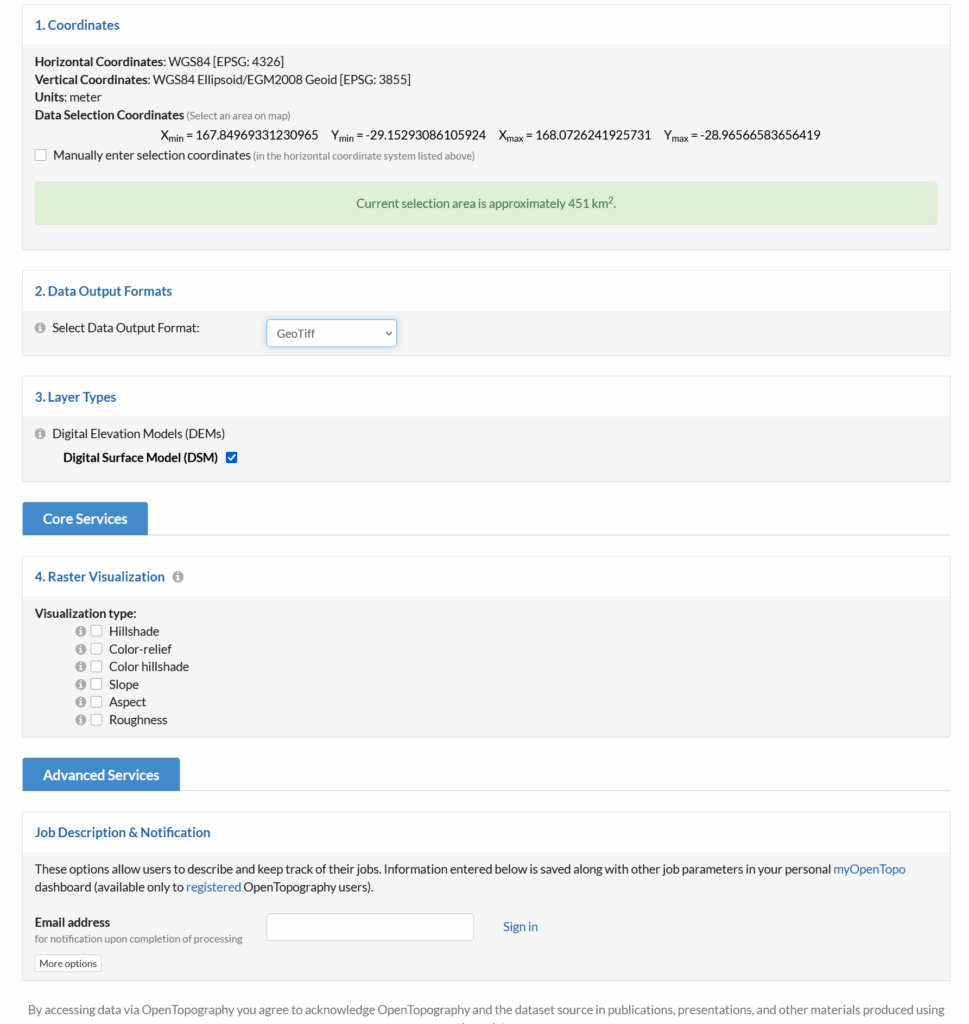
Looks like this is my 3rd (and hopefully final) post on the topic of loading Digital Elevation Models / Topographic data into Forsk Atoll, because this time, we’ve got global data, which allows us to Digital Elevation Models, at 30m resolution, for anywhere on the planet.
The Copernicus DEM is a Digital Surface Model (DSM) which represents the surface of the Earth including buildings, infrastructure and vegetation. This DSM is derived from an edited DSM named WorldDEM, where flattening of water bodies and consistent flow of rivers has been included. In addition, editing of shore- and coastlines, special features such as airports, and implausible terrain structures has also been applied.
The WorldDEM product is based on the radar satellite data acquired during the TanDEM-X Mission, which is funded by a Public Private Partnership between the German State, represented by the German Aerospace Centre (DLR) and Airbus Defence and Space. OpenTopography is providing access to the global GLO-30 Defence Gridded Elevation Data (DGED) 2023_1 version of the data hosted by ESA via the PRISM service. Details on the Copernicus DSM can be found on this ESA site.
This is a tool for a job, 30m resolution is not crazy high – LIDAR scans achieve sub 1m accuracy, but aren’t available everywhere, where as the COP30 dataset is global, meaning we can do RF design for anywhere on the planet.
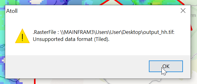
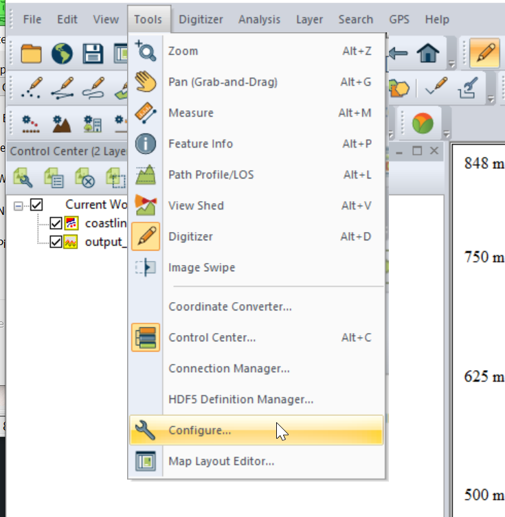
So how do we get this into Atoll to do RF modeling?
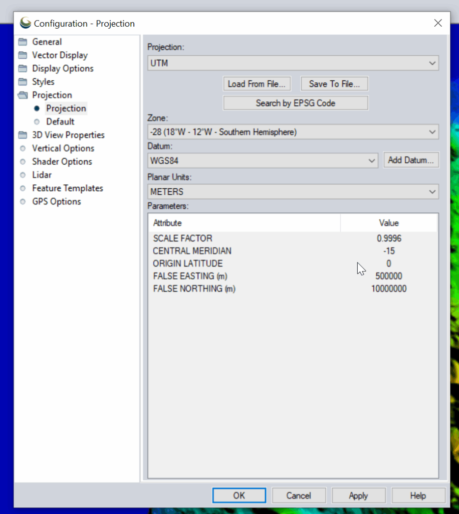
I had to re-project the data, so inside Global Mapper I had to go to Tools -> Configure.
Then change the projection to UTM and use the UTM Zone Finder to find out what zone I needed.
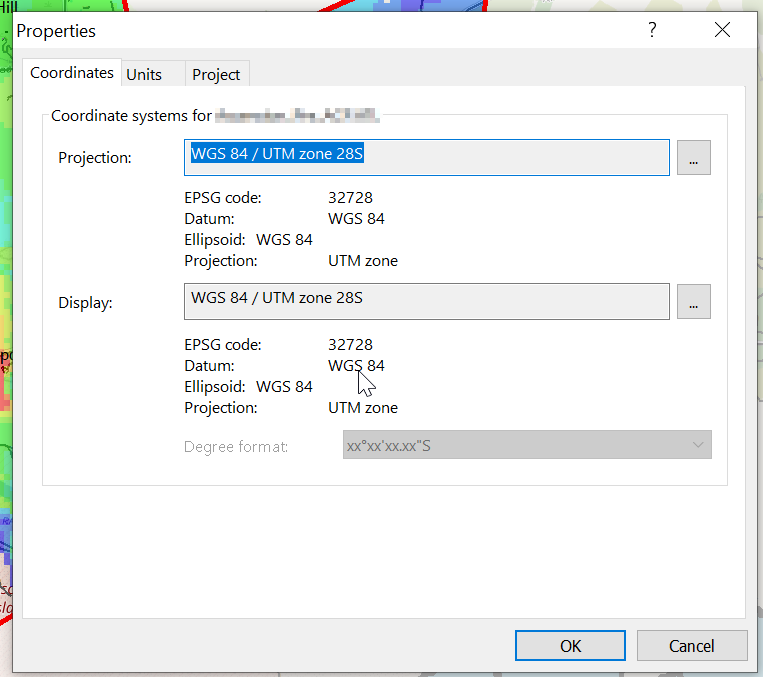
Then I exported the data as an Erdas Imagine file and was able to imported happily into Atoll, after setting the matching projection in Atoll (Which you generally do at the start of the project).
Some questions I wanted to impirically answer with Elixir:
Does the size of value of a Map or ETS object impact the time it takes to retrive a given record (specifically to find that key from others)?
Does the number of keys in ETS or a Map impact the time it takes to retrive a given record?
So what did I find:
Question: Does the size of value of a Map or ETS object impact the time it takes to retrive a given record (specifically to find that key from others)?
Answer: In Maps, the impact of a 100x larger payload being written has a fairly minimal (4% impact) on read speed, but this is ~30% when using ETS.
Methodology used:
Compared 100000 and 100 byte payloads for read and write times.
ETS Write is 24% slower with the larger payload (That’s to be expected, we’ve got more data to copy)
ETS Read is 30% slower with the larger payload (Suggests that the size of the payload has a bearing on how quickly it can be indexed)
Map Write was 13% slower with the larger payload and the Map read is only 4% slower
=== Results === Payload gen: 0 ms for 100000 bytes
ETS write: 223 ms (448,430.5 writes/sec) ETS read: 15933 ms total (933,910.8 reads/sec)
Map write: 108 ms (925,925.9 writes/sec) Map read: 2355 ms total (6,318,471.3 reads/sec)
  @reads 14_880_000
  @distinct 100_000
  @payload_bytes 100
=== Results ===
Payload gen: 0 ms for 100 bytes

ETS write:   177 ms (564,971.8 writes/sec)
ETS read:    11149 ms total (1,334,648.8 reads/sec)

Map write:   125 ms (800,000.0 writes/sec)
Map read:    2470 ms total (6,024,291.5 reads/sec)
Question: Does the number of keys in ETS or a Map impact the time it takes to retrive a given record?
Answer: Writing 1000 records is of course super quick. That much should be obvious, but the retrive / read time is what I’m interested in here.
ETS: Yes, there is a ~40% performance hit in retriving a record from an ETS DB with 14m records than a DB with 1k records. This doesn’t appear to be linear, but there is an impact.
Map: Boy howdy, there’s a 10x increase in the time to get data when the database is larger than smaller. This is probably to do with how simple Maps are, compared to ETS which is definatley a better tool for the job when working with more records.
This led to an interesting realization, Map is faster at smaller sets of data (more keys, not larger values), but ETS is faster for larger data sets (again more keys, not coutning the values), and there’s a break-even point for ETS usage.
TL;DR – ETS – Number of keys has a mangable impact (40%) on retrive time. Map – Number of keys has a very real impact (10x) impact on read times.
Compared 1000 distinct keys vs 14.8m distinct keys.
  @reads 14_880_000
  @distinct 1000
  @payload_bytes 1000
ETS write:   1 ms (1,000,000.0 writes/sec)
ETS read:    9769 ms total (1,523,185.6 reads/sec)

Map write:   9 ms (111,111.1 writes/sec)
Map read:    1292 ms total (11,517,027.9 reads/sec)
  @reads 14_880_000
  @distinct 14_880_000
  @payload_bytes 1000
ETS write:   26176 ms (568,459.7 writes/sec)
ETS read:    16363 ms total (909,368.7 reads/sec)

Map write:   45503 ms (327,011.4 writes/sec)
Map read:    12926 ms total (1,151,168.2 reads/sec)
SMSc can send an SRI-for-SM, and if the subscriber is absent, the response can include the informServiceCenter message, which lets the SMSc know if it will get sent an alertServiceCentre message when the subscriber comes back online (sends an UpdateLocation).
This means that the SMSc can be notified when it can deliver the message to the subscriber.
It’s got a bunch of flags, which equate to:
sc-AddressNotIncluded means the service center address from the SRI-for-SM was not included in the Message Waiting Data file (and therefore will not get notified via AlertSC when the subscriber comes back online).
If it’s sc-AddressNotIncluded is set to False it means that the service center address has been added to the Message Waiting Data file, so will get an alertServiceCenter message when the sub comes back online (Double negative).
mnrf-Set means Mobile subscriber Not Reachable (Not registered on any MSC)
mcef-Set means Memory Capacity Exceeded Flag is set as the HLR has run out of memory in the Message Waiting Data file and cannot store any more data (So you won’t get notified via AlertSC when the subscriber comes back online)
mnrg-Set is for Mobile subscriber Not Reachable for GPRS (When using SGSN delivery is not registered for packet service).
mnr5g-Set means the SC will get notified when the subscriber becomes reachable from 5G serving nodes.
mnr5gn3g is a mystery – The only references to it I can find are in the ASN1 spec (hence why Wireshark decodes it) but as to its purpose, I can only guess.
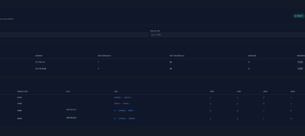
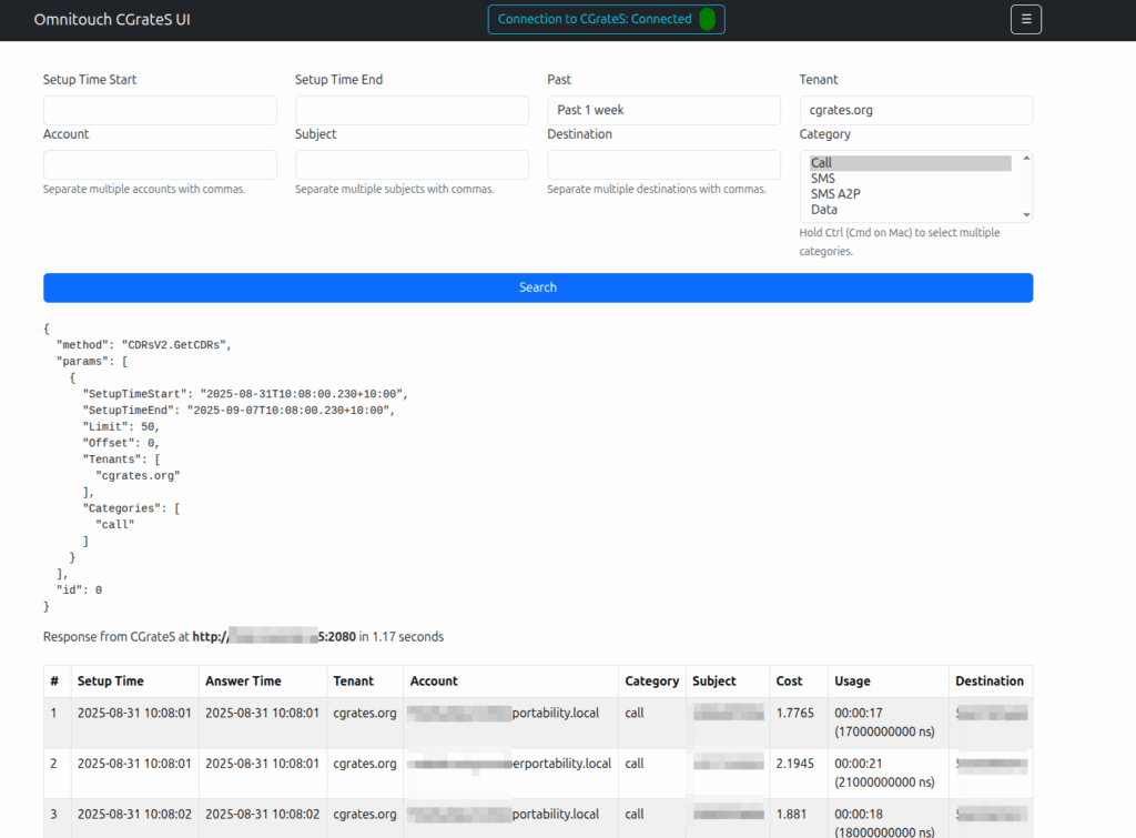
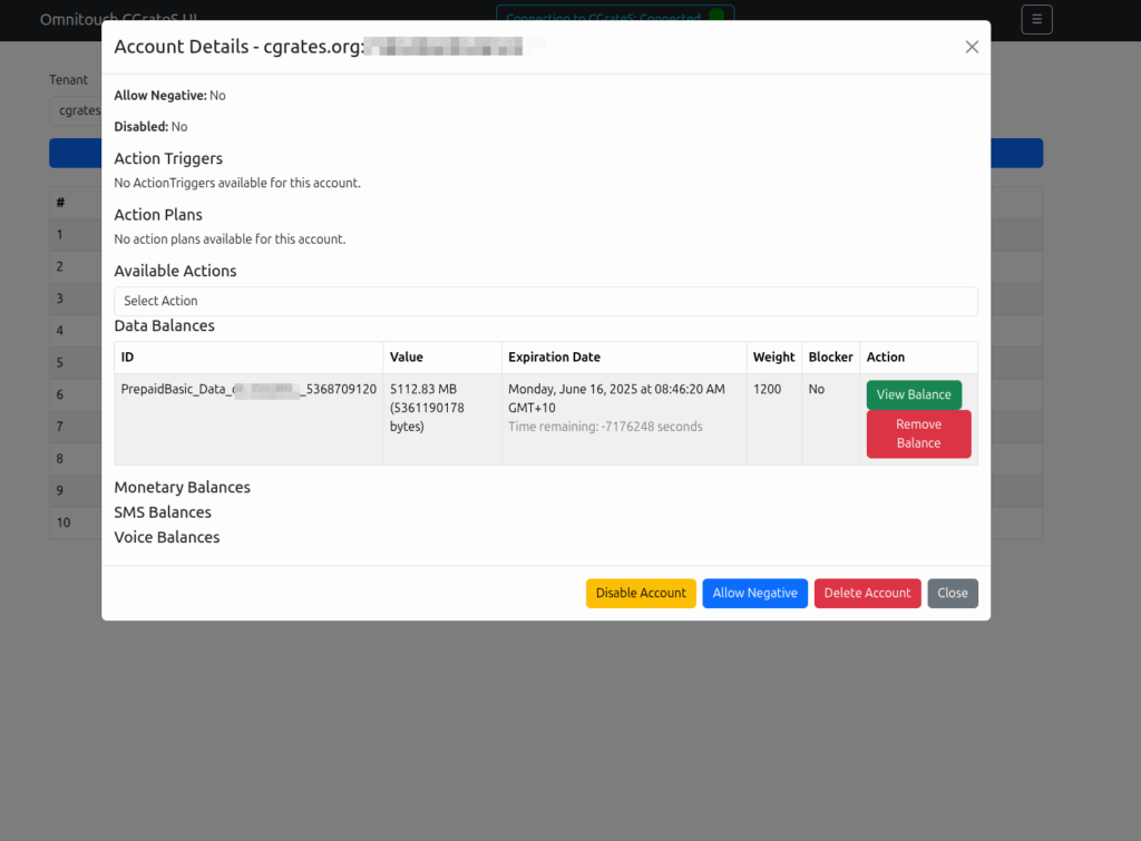
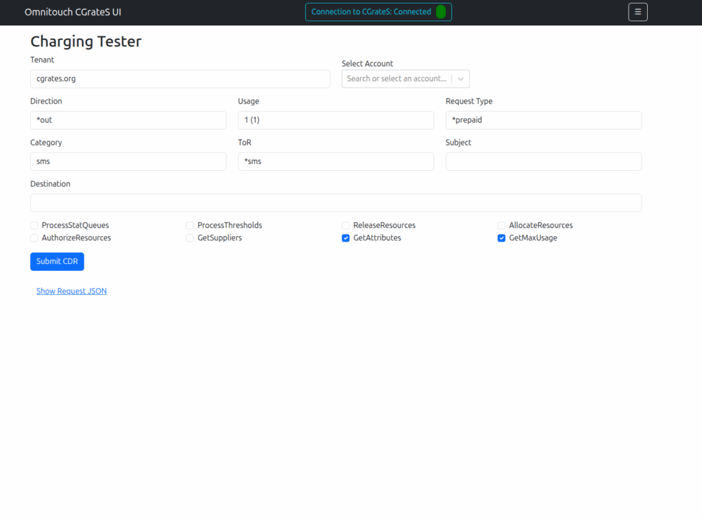
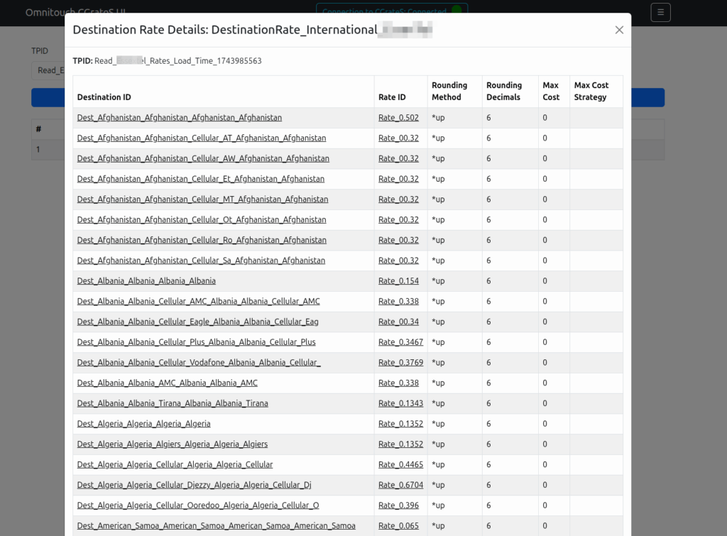
Working a lot with CGrateS I found myself doing the same tasks somewhat regularly, one common task was being asked to get CDRs for a certain thing on an ad-hoc basis, ie “Can you get the call records for XXXX for last month?” or “How much did we spend on calls to YY this quarter?” or “How many GB of data did roamers use on these 3 cell cites this week?”
As those were all CDR related queries, I knocked up a quick React Web UI to search CDRs.
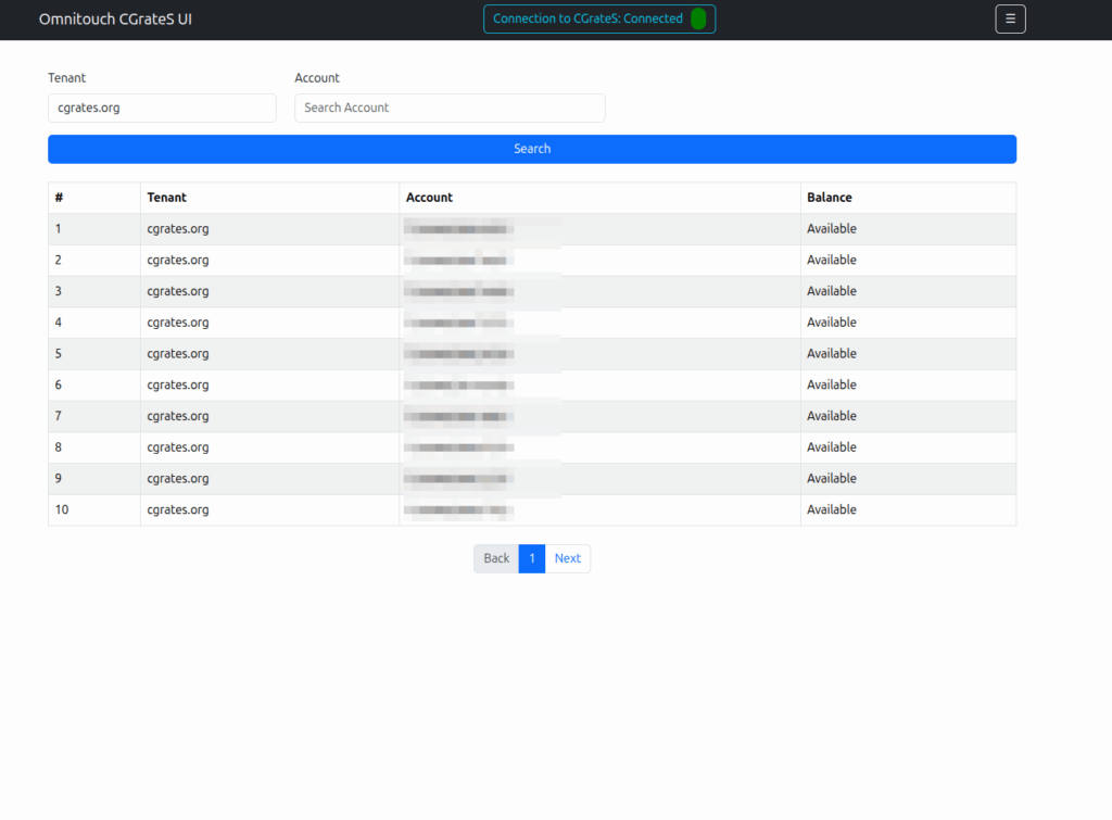
Then we introduced accounts with balances, and there were queries about checking balances, adding roaming packs, etc.
And then things just kinda spiraled…
Managing Actions and Action Plans, rates, simulating cost, Attributes, SessionS, etc, etc.
This isn’t meant as a GUI – If you don’t know how CGrateS works, this tool won’t help you.
But if you’re already working with CGrateS and sending random HTTP POSTs of JSON blobs from your language of choice, this a toolbox to manipulate data will hopefully be useful to you.
I think of it as kinda like Postman but a bit simpler and just focused on CGrateS.
At the time of writing it can view/manage: Searching and exporting CDRs
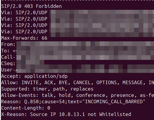
Whenever I reject a call, or hang it up, I like to provide some extra info in the response to help explain why the server made the decision, so anyone looking at the traces will understand.
So you try to pick the most appropriate hangup cause code for your scenario, but it’s not always clear to the other party why you’re hanging up the call.
What we can do is include a SIP header to explain it, X-Dbg or X-Reason or something similar, to provide some context.
<action application="set" data="sip_rh_X-Reason=Source IP not Whitelisted"/>
<action application="hangup" data="INCOMING_CALL_BARRED"/>
The sip_rh_ (SIP Response headers) variable is used to set the headers in the SIP response to reject the call.
By including this before the calling the hangup application, FreeSWITCH will add those headers when sending the hangup.
- name: Fetch the DataDB dump from remote cgrates to local machine fetch: src=/tmp/redis_dump_{{ inventory_hostname }}_{{ ts }}.rdb dest={{ backup_path }}/ flat=yes
Obviously you need to backup your .json config files, but to restore is just a matter of restoring the StorDB data with MySQL on the new machine, copying the Redis database into /var/lib/redis/dump.rdb on the new machine, and starting MySQL, Redis and CGrateS.
A concept that’s always been a bit unclear to me was how the Sh Profile, XCAP data for call forwarding / barring and RepositoryData all fit together.
Let’s start off with the basics.
The Diameter Sh interface sits between an Application Server (Typically TAS, SMSc, XCAP server, etc) and the HSS.
This AS can run a Diameter User Data Request to get the contents of Sh Data, which is returned in the User Data AVP (702) for a given subscriber.
Application Servers can also subscribe to be notified of changes in the Sh data on the HSS, by sending a Subscriber Notification Request, and when the data changes they’ll get a “Push Notification Request” to inform them of the change.
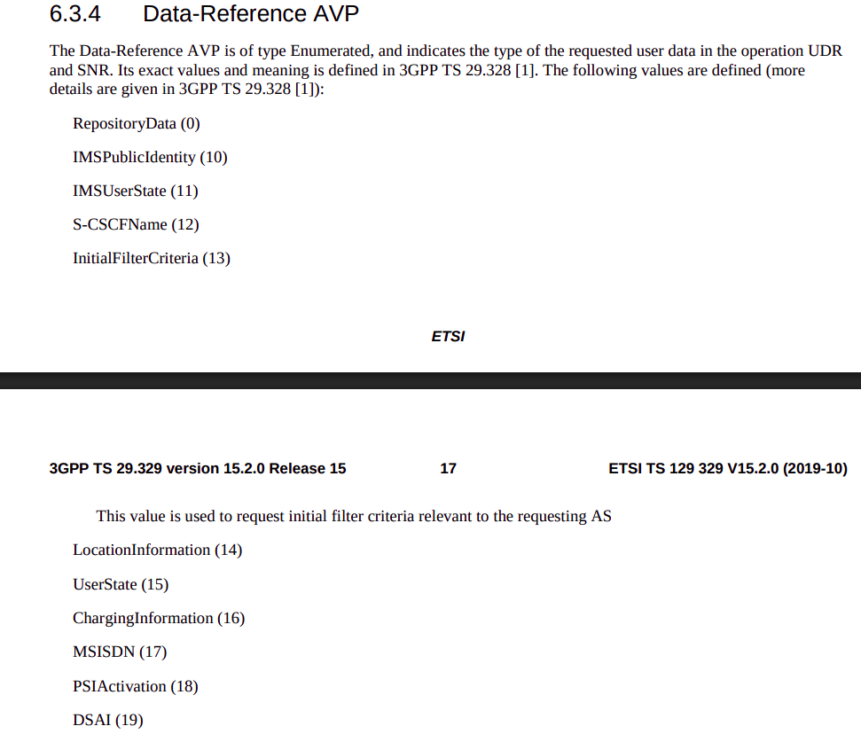
When sending this User Data Request the AS can specify what data it wants to get returned, for example an AS might want to know the current S-CSCF of a given subscriber, in which case, the AS would set the DataReference AVP (703) to 12 for S-CSCFName.
Not the complete list…
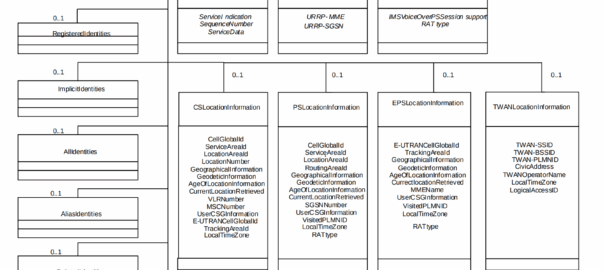
The the AS can request can be public and private identities (IMSIs and MSISDNs), location in the PS and CS networks, TADS info, SRVCC parameters, etc, etc.
Data like TADS Info, CS and PS network location, Public and Private identities, come from the HSS and cannot be modified, these values either come from the static subscriber definition in the HSS (what was set when provisioning the subscriber), or based on the subscriber’s state (ie where they’re registered on the network).
RepositoryData
But there is a section of data we can request the HSS return called RepositoryData which can be modified/updated by the end user or other applications in the network (Modified by ASes), via a Profile Update Request.
This data is where we put the call forwarding, call barring, caller ID presentation/restriction info – The HSS doesn’t really care what is stored in RepositoryData, it’s just a transparent place to store this data.
Think of it as a simple folder containing text files, each text file has a name (ServiceNotification) which allows us to reference the blobs of data by name, a SequenceNumber to identify duplicates, and then the actual contents of the file itself ServiceData.
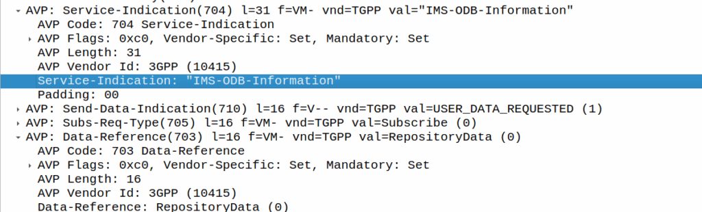
We can then request the contents of these files from the HSS by calling DataReference of RepositoryData and setting the ServiceIndication to be the “file” we want returned to the AS by the HSS.
For example, if the Data-Reference AVP is set to zero (Repository Data) and the Service-Indicator AVP is set to “IMS-ODB-Information” the HSS will return the data for the file IMS-ODB-Information of repository data.
This RepositoryData is just “transparent” storage of XML data by the HSS, and this is where we’d put Call Forwarding, Operator Defined Barring and CLI presentation/restriction parameters.
In theory you could also store 3rd party custom unstructured data here (Move over AWS S3 buckets, I’m moving all my storage to Diameter!), but it’s not commonly used beyond call routing parameters.
The two most common types of ServiceIndication keys you’ll see stored in RepositoryData are MMTEL-Services and IMS-ODB-Information. Each of these are defined by their own XML spec, but the MMTel-Services key is where all of our Call Forwarding, Caller ID Presentation/Restriction parameters live, while IMS-ODB-Information contains the parameters for Operator Defined barring – Both of these XML definitions we’ll dive into in a post of their own, but for now all you need to remember is that they’re stored transparently as XML on the HSS.
An example use case of this would be when a user wants to manage their call forwarding data via XCAP. When the user pulls up the Call Forwarding menu on their phone, the first entry point will be the XCAP Server (AS) to get all the User Data for MMTelServices, so it’ll do that via a Diameter User Data Request with the DataReference set to RepositoryData and the ServiceIndication set to MMTel-Service so the XCAP server can pass the full XCAP XML body to the UE.
The UE can then update this data, and the XCAP server just sends a Profile Update Request to push the updated XML to be stored on the HSS.
Fitting this all Together
Data sent to the AS by the HSS will always include the <Sh-Data> XML, but the child keys within it depend on the data the AS requested under the Data-Reference.
If we requested IMSI as the DataReference, then the returned XML might look like:
<Sh-Data>
 <imsi>9990112345677</imsi>
</Sh-Data>
Likewise, if you requested IMSPublicIdentity as the DataReference you’d get:
The spec goes into full detail on all the possible keys, but in short, when the AS queries the data for the provided DataReference, the HSS sends back an Sh-Data XML body containing at a minimum those keys.
This one replaces nicktest.com with mobile.operatorx.numberportability.local and after that replaces 10.171.2.134 with fixed.operatorx.numberportability.local
Recently we ran into an issue with certain devices while roaming not including an ICSCI field in the Contact header while registering onto the IMS, leading to MT call failures.
So what is ICSI and why were these calls failing?
The IMS standards are littered with novel ideas for smart telephony features that no one ever implimented, and presents a minefield of conditionals about features you never even knew existed.
Today’s dead feature is the “IMS Communication Service Identifier” (ICSI), no, it’s not a TV show about IMS Crime Scene Investigators (don’t steal my pitch), instead ICSI identifies IMS services by using “IMS Enablers” which allows multiple IMS applications to run on the phone.
It’s like a VLAN or a VRF but for IMS, one IMS stack but multiple sub-IMS stacks I guess.
Why would you want to do this you might ask? Well, the example from the Specs is if you were using OMA’s very short lived OMA Instant Messaging and Presence application, which uses SIP for transport, but needs the SIP messages routed to the OMA client application in the phone, rather than the standard IMS SIP client in the phone for making calls / texts.
Alternately, you could have a mobile PBX application for office workers, and with a different ICSI this could use a secondary dialler with a contacts list and presence for all your co-workers, these sorts of “sub” IMS clients and applications were possible with ICSI.
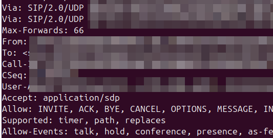
So how does it actually work? Well, it’s stupid simple, during register the phone indicates in the Contact header what ICSI applications that client supports.
When a call is made by the UE based on this value the iFCs can route to different Application Servers based on the values.
For mobile originated calls, the terminal in this scenario is kinda meant to work like a SIP Proxy, dispatching a SIP message to the correct application (in the terminal another IMS client that spoke to the main phone).
In reality though, there is only one ICSI service seen in 99.999% of IMS traffic and that’s the 3gpp-service.ims.icsi.mmtel ICSI, used by IMS clients to denote that they support IMS Multimedia Telephony, aka just normal IMS.
For reasons best know to VENDOR X (you know who you are) their phones include the 3gpp-service.ims.icsi.mmtel in the Contact header when registering on the home network, but while registering while roaming do not include this.
Our TAS ignores the lack of ICSI for mmtel in the contact on regular MT calls, but one of the other TAS vendors in the mix got grumpy because it was missing, and they didn’t have a contact for MMtel for the registered subscriber.
In the end we rewrote the headeron on our CSCFs before passing it to their TAS, which resolved the issue.
Who’s in the wrong? Well, the particular phone vendor who doesn’t include MMtel in the ICSI Contact, but that’s not going to change any time soon. So as the old saying goes, if the mountain won’t come to Mohammed… Mohammed will rewrite SIP headers.
Here’s a Kamailio question I posed to the mailing list the other day:
I’m working on a scenario with a Kamailio box with a private IP, with a public IP 1:1 NATed to it (but the VM does not see the public IP on the NICs).
When forwarding requests to some hosts I want to set the Via address to be the public IP, but when forwarding requests to other hosts I want to leave the Via address to the internal IP address.
If I set the Advertise parameter in the bind config, this sets the Via to the advertised IP, but I’m seeing that address used even when communicating with hosts on the private IP.
Of course if the IP was on the VM itself I could use $fs or force_send_socket, but that only works if I’ve got the public IP bound, which I can’t do.
Is there a simple way to set / override what IP gets baked into the Via header?
Where you’ve got multiple IPs on your box, you can include the advertise paramter to override the IP you show, for example if you have the IP 100.64.253.251 on your NIC, but you’ve NATed the traffic and instead want to show 1.2.3.4 you can set this in the general config:
But then every message Kamailio forwards, will contain the 1.2.3.4 address int he Via header. For my scenario, this didn’t work, as I wanted to only use the 1.2.3.4 IP when communicating with hosts outside of the RFC1918 address space (only conditionally use that address).
Because of this I couldn’t use the advertise option, but I found the set_advertised_address() function to use in my routing logic, where I set the advertised address just on the given routes I care about:
#General Config:
listen=tcp:100.64.253.251:5061


#My routing blocks that go to hosts outside RFC1918 address space:
                rtpengine_manage("media-address=1.2.3.4");
                set_advertised_address("1.2.3.4:5060");
                msg_apply_changes();
So now any packets by default will have a Via of 100.64.253.251 but when I want to I can set the Via to the 1.2.3.4 public IP (and I do the same in RTPengine).
I’ve been facing an issue in Vscode for a long time where when I’ve printed a lot of data to the terminal, everything gets really unresponsive – Scrolling through the results is like I’m drunk it’s so unresponsive, and I’ve tried a bunch of stuff to fix it.
Here’s the Benchee benchmarks for a function in Elixir that happens to print a lot of data to the terminal, if I run it in Vscode:
A meagre 12.4 IPS on that function, but not only that but I see the CPU usage spike and the computer becomes unsuable.
But if I run in Ubuntu’s default terminal (GNOME Terminal):
5 fold increase and I don’t even see CPU spike above 30%.
So what gives?
Here’s what I’ve tried:
Disable hardware acceleration
Change scrollback limits in VScode
Changed scrollback limits in the terminal
Removed all extensions
Defaulted config
Same thing.
Still stuck, I was kinda hoping this would be a “here’s how I fixed it” post. But it’s not. Sorry hopeful people with the same issue, I’ll update this if I ever get to the bottom of it…