SMSc can send an SRI-for-SM, and if the subscriber is absent, the response can include the informServiceCenter message, which lets the SMSc know if it will get sent an alertServiceCentre message when the subscriber comes back online (sends an UpdateLocation).
This means that the SMSc can be notified when it can deliver the message to the subscriber.
It’s got a bunch of flags, which equate to:
sc-AddressNotIncluded means the service center address from the SRI-for-SM was not included in the Message Waiting Data file (and therefore will not get notified via AlertSC when the subscriber comes back online).
If it’s sc-AddressNotIncluded is set to False it means that the service center address has been added to the Message Waiting Data file, so will get an alertServiceCenter message when the sub comes back online (Double negative).
mnrf-Set means Mobile subscriber Not Reachable (Not registered on any MSC)
mcef-Set means Memory Capacity Exceeded Flag is set as the HLR has run out of memory in the Message Waiting Data file and cannot store any more data (So you won’t get notified via AlertSC when the subscriber comes back online)
mnrg-Set is for Mobile subscriber Not Reachable for GPRS (When using SGSN delivery is not registered for packet service).
mnr5g-Set means the SC will get notified when the subscriber becomes reachable from 5G serving nodes.
mnr5gn3g is a mystery – The only references to it I can find are in the ASN1 spec (hence why Wireshark decodes it) but as to its purpose, I can only guess.
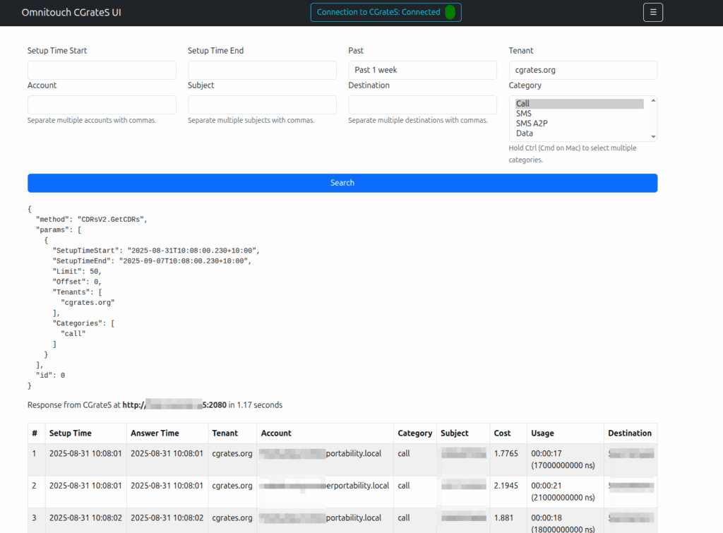
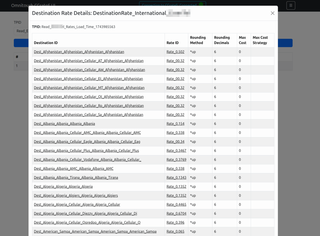
Working a lot with CGrateS I found myself doing the same tasks somewhat regularly, one common task was being asked to get CDRs for a certain thing on an ad-hoc basis, ie “Can you get the call records for XXXX for last month?” or “How much did we spend on calls to YY this quarter?” or “How many GB of data did roamers use on these 3 cell cites this week?”
As those were all CDR related queries, I knocked up a quick React Web UI to search CDRs.
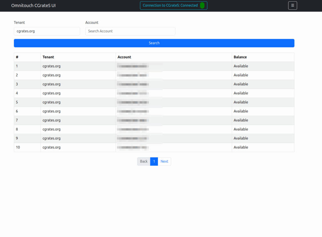
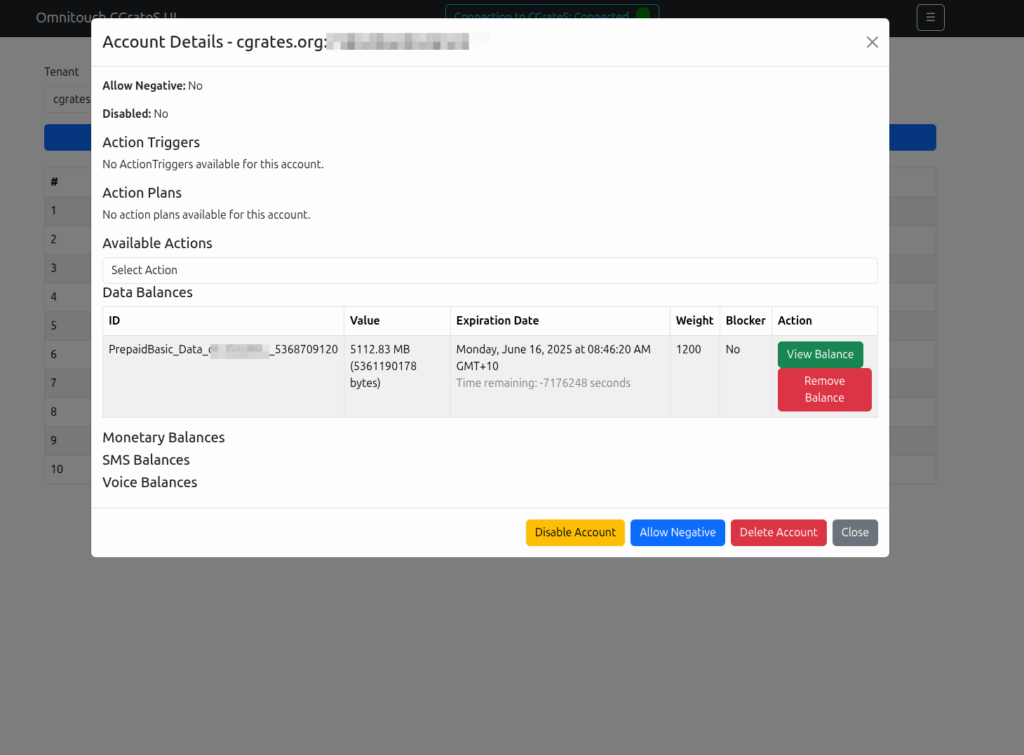
Then we introduced accounts with balances, and there were queries about checking balances, adding roaming packs, etc.
And then things just kinda spiraled…
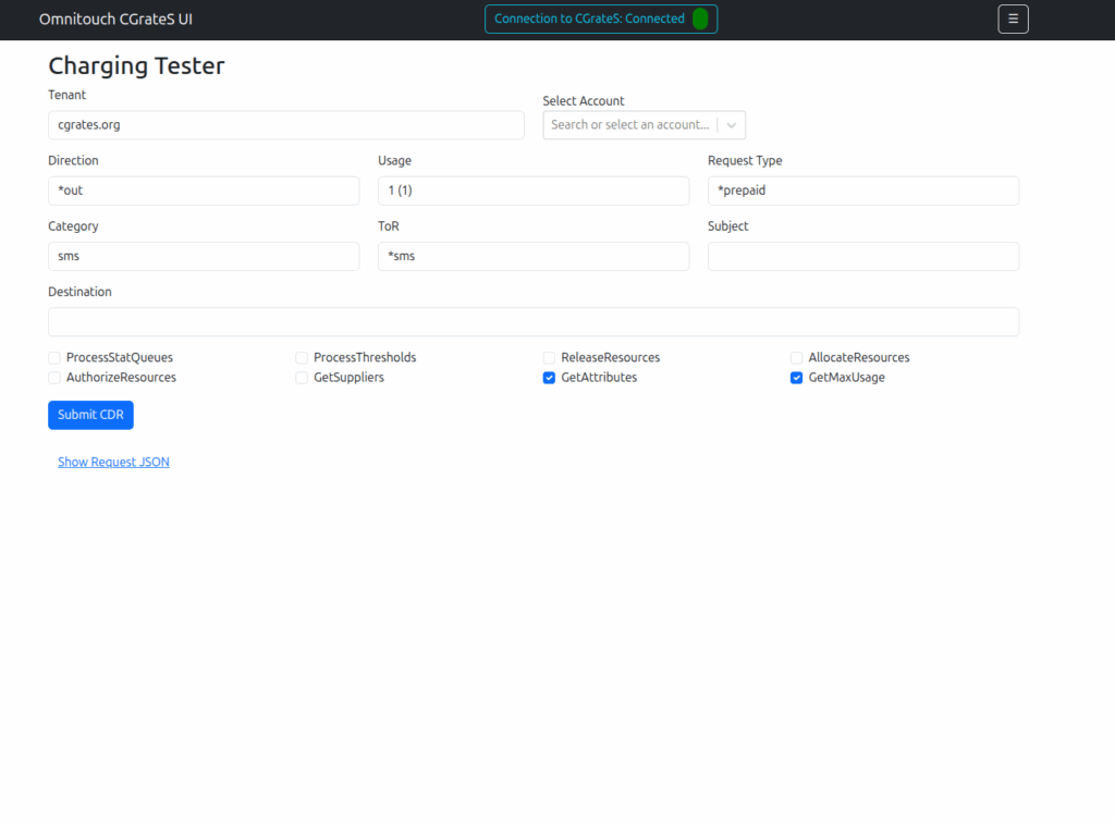
Managing Actions and Action Plans, rates, simulating cost, Attributes, SessionS, etc, etc.
This isn’t meant as a GUI – If you don’t know how CGrateS works, this tool won’t help you.
But if you’re already working with CGrateS and sending random HTTP POSTs of JSON blobs from your language of choice, this a toolbox to manipulate data will hopefully be useful to you.
I think of it as kinda like Postman but a bit simpler and just focused on CGrateS.
At the time of writing it can view/manage: Searching and exporting CDRs
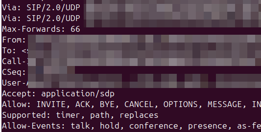
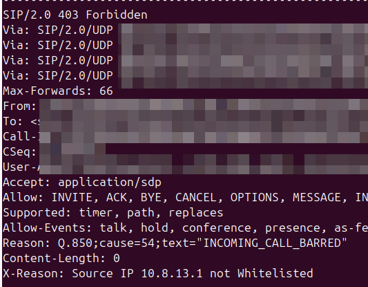
Whenever I reject a call, or hang it up, I like to provide some extra info in the response to help explain why the server made the decision, so anyone looking at the traces will understand.
So you try to pick the most appropriate hangup cause code for your scenario, but it’s not always clear to the other party why you’re hanging up the call.
What we can do is include a SIP header to explain it, X-Dbg or X-Reason or something similar, to provide some context.
<action application="set" data="sip_rh_X-Reason=Source IP not Whitelisted"/>
<action application="hangup" data="INCOMING_CALL_BARRED"/>
The sip_rh_ (SIP Response headers) variable is used to set the headers in the SIP response to reject the call.
By including this before the calling the hangup application, FreeSWITCH will add those headers when sending the hangup.
- name: Fetch the DataDB dump from remote cgrates to local machine fetch: src=/tmp/redis_dump_{{ inventory_hostname }}_{{ ts }}.rdb dest={{ backup_path }}/ flat=yes
Obviously you need to backup your .json config files, but to restore is just a matter of restoring the StorDB data with MySQL on the new machine, copying the Redis database into /var/lib/redis/dump.rdb on the new machine, and starting MySQL, Redis and CGrateS.
A concept that’s always been a bit unclear to me was how the Sh Profile, XCAP data for call forwarding / barring and RepositoryData all fit together.
Let’s start off with the basics.
The Diameter Sh interface sits between an Application Server (Typically TAS, SMSc, XCAP server, etc) and the HSS.
This AS can run a Diameter User Data Request to get the contents of Sh Data, which is returned in the User Data AVP (702) for a given subscriber.
Application Servers can also subscribe to be notified of changes in the Sh data on the HSS, by sending a Subscriber Notification Request, and when the data changes they’ll get a “Push Notification Request” to inform them of the change.
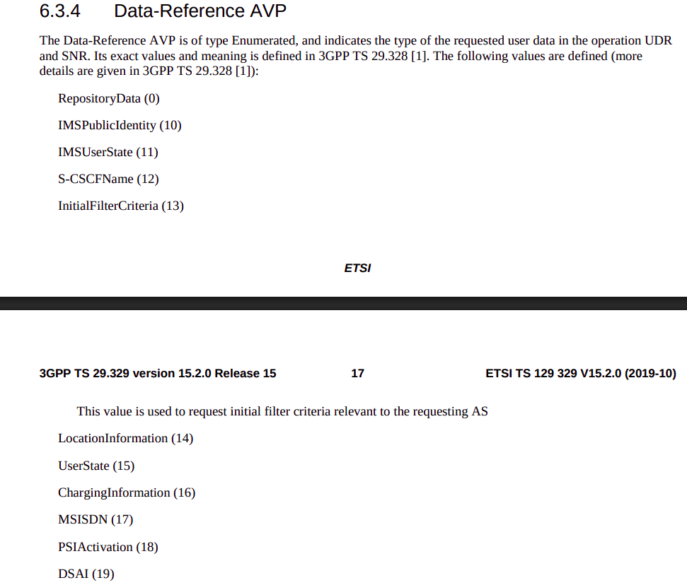
When sending this User Data Request the AS can specify what data it wants to get returned, for example an AS might want to know the current S-CSCF of a given subscriber, in which case, the AS would set the DataReference AVP (703) to 12 for S-CSCFName.
Not the complete list…
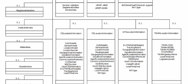
The the AS can request can be public and private identities (IMSIs and MSISDNs), location in the PS and CS networks, TADS info, SRVCC parameters, etc, etc.
Data like TADS Info, CS and PS network location, Public and Private identities, come from the HSS and cannot be modified, these values either come from the static subscriber definition in the HSS (what was set when provisioning the subscriber), or based on the subscriber’s state (ie where they’re registered on the network).
RepositoryData
But there is a section of data we can request the HSS return called RepositoryData which can be modified/updated by the end user or other applications in the network (Modified by ASes), via a Profile Update Request.
This data is where we put the call forwarding, call barring, caller ID presentation/restriction info – The HSS doesn’t really care what is stored in RepositoryData, it’s just a transparent place to store this data.
Think of it as a simple folder containing text files, each text file has a name (ServiceNotification) which allows us to reference the blobs of data by name, a SequenceNumber to identify duplicates, and then the actual contents of the file itself ServiceData.
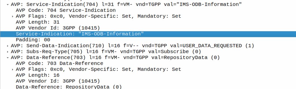
We can then request the contents of these files from the HSS by calling DataReference of RepositoryData and setting the ServiceIndication to be the “file” we want returned to the AS by the HSS.
For example, if the Data-Reference AVP is set to zero (Repository Data) and the Service-Indicator AVP is set to “IMS-ODB-Information” the HSS will return the data for the file IMS-ODB-Information of repository data.
This RepositoryData is just “transparent” storage of XML data by the HSS, and this is where we’d put Call Forwarding, Operator Defined Barring and CLI presentation/restriction parameters.
In theory you could also store 3rd party custom unstructured data here (Move over AWS S3 buckets, I’m moving all my storage to Diameter!), but it’s not commonly used beyond call routing parameters.
The two most common types of ServiceIndication keys you’ll see stored in RepositoryData are MMTEL-Services and IMS-ODB-Information. Each of these are defined by their own XML spec, but the MMTel-Services key is where all of our Call Forwarding, Caller ID Presentation/Restriction parameters live, while IMS-ODB-Information contains the parameters for Operator Defined barring – Both of these XML definitions we’ll dive into in a post of their own, but for now all you need to remember is that they’re stored transparently as XML on the HSS.
An example use case of this would be when a user wants to manage their call forwarding data via XCAP. When the user pulls up the Call Forwarding menu on their phone, the first entry point will be the XCAP Server (AS) to get all the User Data for MMTelServices, so it’ll do that via a Diameter User Data Request with the DataReference set to RepositoryData and the ServiceIndication set to MMTel-Service so the XCAP server can pass the full XCAP XML body to the UE.
The UE can then update this data, and the XCAP server just sends a Profile Update Request to push the updated XML to be stored on the HSS.
Fitting this all Together
Data sent to the AS by the HSS will always include the <Sh-Data> XML, but the child keys within it depend on the data the AS requested under the Data-Reference.
If we requested IMSI as the DataReference, then the returned XML might look like:
<Sh-Data>
 <imsi>9990112345677</imsi>
</Sh-Data>
Likewise, if you requested IMSPublicIdentity as the DataReference you’d get:
The spec goes into full detail on all the possible keys, but in short, when the AS queries the data for the provided DataReference, the HSS sends back an Sh-Data XML body containing at a minimum those keys.
This one replaces nicktest.com with mobile.operatorx.numberportability.local and after that replaces 10.171.2.134 with fixed.operatorx.numberportability.local
Recently we ran into an issue with certain devices while roaming not including an ICSCI field in the Contact header while registering onto the IMS, leading to MT call failures.
So what is ICSI and why were these calls failing?
The IMS standards are littered with novel ideas for smart telephony features that no one ever implimented, and presents a minefield of conditionals about features you never even knew existed.
Today’s dead feature is the “IMS Communication Service Identifier” (ICSI), no, it’s not a TV show about IMS Crime Scene Investigators (don’t steal my pitch), instead ICSI identifies IMS services by using “IMS Enablers” which allows multiple IMS applications to run on the phone.
It’s like a VLAN or a VRF but for IMS, one IMS stack but multiple sub-IMS stacks I guess.
Why would you want to do this you might ask? Well, the example from the Specs is if you were using OMA’s very short lived OMA Instant Messaging and Presence application, which uses SIP for transport, but needs the SIP messages routed to the OMA client application in the phone, rather than the standard IMS SIP client in the phone for making calls / texts.
Alternately, you could have a mobile PBX application for office workers, and with a different ICSI this could use a secondary dialler with a contacts list and presence for all your co-workers, these sorts of “sub” IMS clients and applications were possible with ICSI.
So how does it actually work? Well, it’s stupid simple, during register the phone indicates in the Contact header what ICSI applications that client supports.
When a call is made by the UE based on this value the iFCs can route to different Application Servers based on the values.
For mobile originated calls, the terminal in this scenario is kinda meant to work like a SIP Proxy, dispatching a SIP message to the correct application (in the terminal another IMS client that spoke to the main phone).
In reality though, there is only one ICSI service seen in 99.999% of IMS traffic and that’s the 3gpp-service.ims.icsi.mmtel ICSI, used by IMS clients to denote that they support IMS Multimedia Telephony, aka just normal IMS.
For reasons best know to VENDOR X (you know who you are) their phones include the 3gpp-service.ims.icsi.mmtel in the Contact header when registering on the home network, but while registering while roaming do not include this.
Our TAS ignores the lack of ICSI for mmtel in the contact on regular MT calls, but one of the other TAS vendors in the mix got grumpy because it was missing, and they didn’t have a contact for MMtel for the registered subscriber.
In the end we rewrote the headeron on our CSCFs before passing it to their TAS, which resolved the issue.
Who’s in the wrong? Well, the particular phone vendor who doesn’t include MMtel in the ICSI Contact, but that’s not going to change any time soon. So as the old saying goes, if the mountain won’t come to Mohammed… Mohammed will rewrite SIP headers.
Here’s a Kamailio question I posed to the mailing list the other day:
I’m working on a scenario with a Kamailio box with a private IP, with a public IP 1:1 NATed to it (but the VM does not see the public IP on the NICs).
When forwarding requests to some hosts I want to set the Via address to be the public IP, but when forwarding requests to other hosts I want to leave the Via address to the internal IP address.
If I set the Advertise parameter in the bind config, this sets the Via to the advertised IP, but I’m seeing that address used even when communicating with hosts on the private IP.
Of course if the IP was on the VM itself I could use $fs or force_send_socket, but that only works if I’ve got the public IP bound, which I can’t do.
Is there a simple way to set / override what IP gets baked into the Via header?
Where you’ve got multiple IPs on your box, you can include the advertise paramter to override the IP you show, for example if you have the IP 100.64.253.251 on your NIC, but you’ve NATed the traffic and instead want to show 1.2.3.4 you can set this in the general config:
But then every message Kamailio forwards, will contain the 1.2.3.4 address int he Via header. For my scenario, this didn’t work, as I wanted to only use the 1.2.3.4 IP when communicating with hosts outside of the RFC1918 address space (only conditionally use that address).
Because of this I couldn’t use the advertise option, but I found the set_advertised_address() function to use in my routing logic, where I set the advertised address just on the given routes I care about:
#General Config:
listen=tcp:100.64.253.251:5061


#My routing blocks that go to hosts outside RFC1918 address space:
                rtpengine_manage("media-address=1.2.3.4");
                set_advertised_address("1.2.3.4:5060");
                msg_apply_changes();
So now any packets by default will have a Via of 100.64.253.251 but when I want to I can set the Via to the 1.2.3.4 public IP (and I do the same in RTPengine).
I’ve been facing an issue in Vscode for a long time where when I’ve printed a lot of data to the terminal, everything gets really unresponsive – Scrolling through the results is like I’m drunk it’s so unresponsive, and I’ve tried a bunch of stuff to fix it.
Here’s the Benchee benchmarks for a function in Elixir that happens to print a lot of data to the terminal, if I run it in Vscode:
A meagre 12.4 IPS on that function, but not only that but I see the CPU usage spike and the computer becomes unsuable.
But if I run in Ubuntu’s default terminal (GNOME Terminal):
5 fold increase and I don’t even see CPU spike above 30%.
So what gives?
Here’s what I’ve tried:
Disable hardware acceleration
Change scrollback limits in VScode
Changed scrollback limits in the terminal
Removed all extensions
Defaulted config
Same thing.
Still stuck, I was kinda hoping this would be a “here’s how I fixed it” post. But it’s not. Sorry hopeful people with the same issue, I’ll update this if I ever get to the bottom of it…
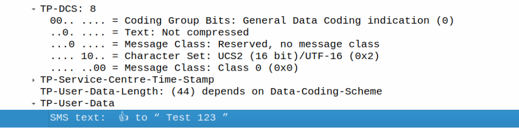
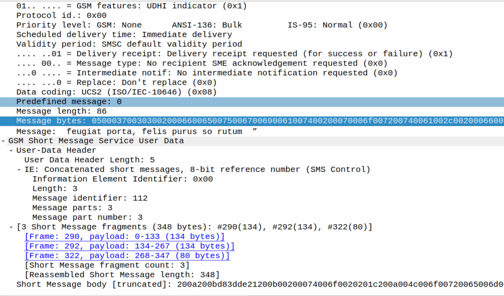
Well Android cleverly has formatted this message so that it has special meaning on Android phones, but non-android phones, will just see:
👍 to ” Test 123″
Breaking it down:
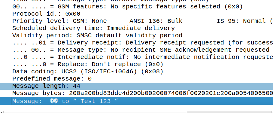
200A is Hair Space followed by 200B which is a Zero Width Space (This is metadata for Google’s messaging app) to denote it’s an emoji. This is really clever, as these characters mean it’s an emoji reaction to a previous SMS, but they don’t render as visible characters if the user is on a phone that doesn’t know how to treat it.
Our UTF-16 thumbs up is represented at D83D DC4D (Surrogate), and then the original message is quoted after it.
As a fun aside, this does not work if the original message was near the limit of a single part message, as the original message is quoted, so what happens then?
Here’s a MO message that’s exactly 160 characters:
If I react, the original message (160 chars, GSM7 data) is included, but as we’re including an emoji, it must be UCS2 (essentially UTF16) as the emoji isn’t part of the GSM7 alphabet.
In this case, this ends up being a 3 part message, the original text has almost doubled in size as it’s now in UTF16 – it was 140 bytes before (140 bytes fits 160 GSM7 characters) but is now 320 bytes (140 characters at 8 bytes each) + the 8 bytes for the hair space + whitespace + 8 more bytes for the emoji + the 6 bytes UDH header per message, brings us to a whopping 347 bytes not including overhead.
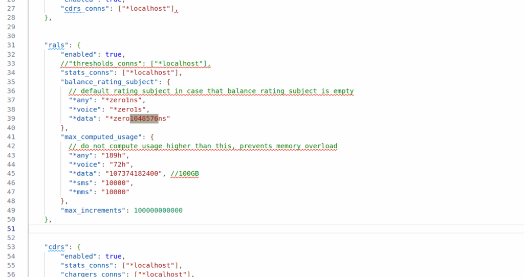
Well CGrateS deducts for each incriment in the usage, and in my case, a usage of 107374182 meant CGrateS was trying to deduct from the balance 107 million times.
But as you can imagine, we don’t actually charge our customers per byte but rather we round up our incriments.
This is where the RatingSubject comes into play. RatingSubject sets what “blocks” of balance get calculated.
For example rather than calculating usage of 107,374,182 bytes, with CGrateS deducting from the balance 107 million times, we could set the value *zero1048576ns which means we’d calculate per Megabyte, so we’re only calculating 102 times 1 megabyte.
Likewise we could set the RatingSubject value to *zero1024ns to get it in Kilobytes.
What’s with the ns suffix? Well CGrateS (actually Go) treats units as duration, and the smallest unit is nanoseconds, but we can ignore the meaning in this context, as just 1 integer unit.
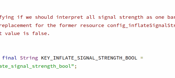
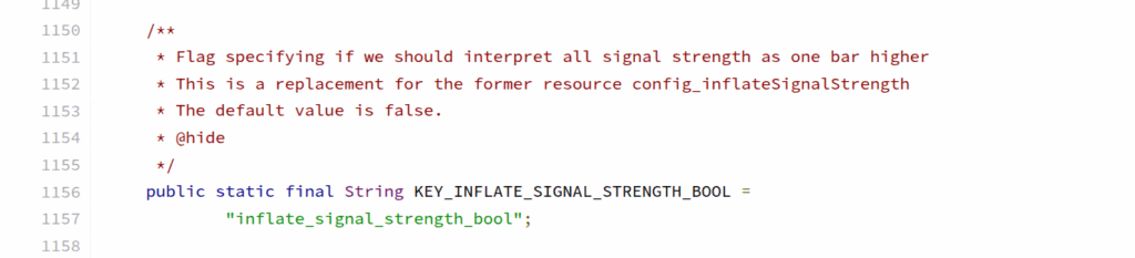
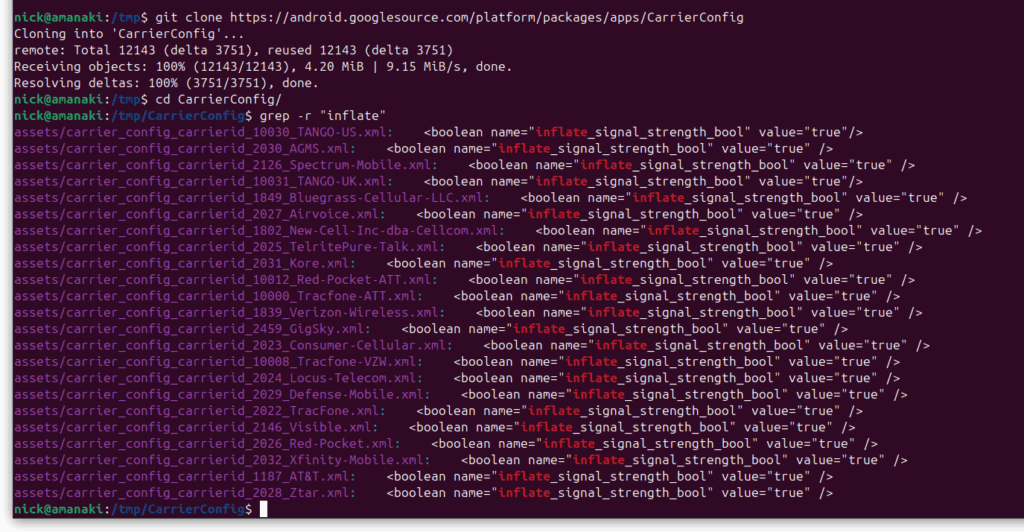
Poking around in Android the other day I found this nugget in Carrier Config manager; a flag (KEY_INFLATE_SIGNAL_STRENGTH_BOOL) to always report the signal strength to the user as one bar higher than it really is.
Notably both AT&T and Verizon have this flag enabled on their networks, I’m not sure who was responsible for requesting this to be added to Android, nor could I find it in the git-blame, but we can see it in the CarrierConfig which contains all the network settings for each of these operators.
Operators are always claiming to have the biggest coverage or the best network, but stuff like this, along with the fake 5G flags, don’t help build trust, especially considering the magic mobile phone antennas which negate the need for all this deception anyway.
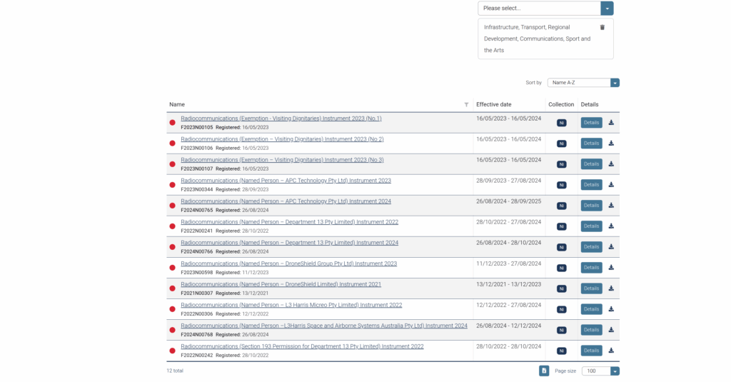
I got this email today from ACMA, the Australian communcations regulator who’s mailing list I subscribe to:
When I first started working, I’d often ride my motorbike to customer job sites with my cabling tools in a milk crate strapped on the back, but at no point did I combine customer cabling with riding the motorcycle – They seem like separate tasks.
So why does a motorbike race except certain people, equipment and cabling from the rules?
Will we see people on bikes traveling at great speed while crunching on Krone?
Leaning into the corners while working on lines?
Well, rather than doing my work I went down the rabbit hole to find out, and it started with ACMA gaving a handy link to the declaration in the email:
Section 54A Exemption – devices used for significant events says:
If you’re just operating your widgets for the purpose of a significant event, it’s cool, you don’t need to worry about complying with ACMA’s Low interference potential devices (LIPD) class license standards.
Section 54A Exemption – devices used for significant events (Some liberty taken)
So why would this exist?
Well, 5 days after the MotoGP wraps up on Philip Island it’s in Malaysia. I assume this loophole exists because there’s a lot of fancy telemetry stuff on the bikes, cameras, engine monitoring, lap time recording, and if MotoGP organizers had to get type-approval for everything and local cabling certification for everything, in every country the operate, when the race moves country to country each week, they’d never get approval for anything.
I did some research to see if this has been used before, and if so where, and came up short, this might be the first time this has been used:
What I did learn is if you’re a big enough wig (For example president of the US), you can get an exemption to the anti-jamming laws, which is used from time to time.
But as for the MotoGP being for their telemetry devices, this is just a guess, if anyone reading this knows definitively how this came to be, and where else this gets used, drop a comment – I’d be curious.
We were testing international roaming for a customer, roaming into the US where one of our team members (shoutout to Cody) is based.
So we sent Cody some SIMs and asked them to run the basic tests for us, but no IMS APN would attach.
We’d get them to power up the phone, fire up a trace on the roaming PGWs, but never seeing an attempt to attach on the IMS APN (No Create Session Request from the SGW in the vPMN).
The operator we were roaming into swore their side was correct – that IMSI was allowed for the IMS APN for testing, but whenever we’d run a trace, same thing, default bearer just fine but no CSR for the IMS APN, as if the IMS APN was blocked on the roaming network (Which is common on networks where you haven’t launched VoLTE but do have data roaming).
The steps we would do is:
Person in the US turns on phone tries to attach
I fire up my computer, get a trace running
Person in the US airplanes the device
I monitor for CSRs on the PGWs for that IMSI
But no CSR for the IMS APN would ever come through.
After a few attempts, here’s what we found was happening:
The phone would get powered up
The phone would roam onto the vPMN in the US and the default bearer would come up
The phone would try to attach to the ims APN, this would work for this SIM which was whitelisted, and the Create Session Request for the ims APN went to the PGW in the hPMN
The ims APN came up as expected
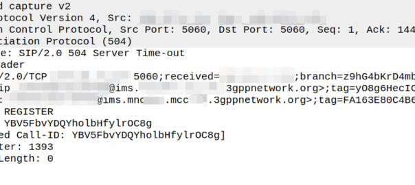
The phone would send a SIP REGISTER (So far so good)
Our IMS had an issue with Rx routing in this scenario, so the SIP REGISTER would timeout, and when it timed out, a 504 error was sent back to the phone by the P-CSCF and it set the Retry-After header to 3600 seconds.
The phone would not try again for as long as that timer value was set.
At this point we’d start a trace, airplane the device, and see no IMS APN attach attempt.
This 504 Timeout would all happen when the phone fired up before we had any traces running, so we weren’t capturing that.
I’d wrongly assumed that airplaning the device after starting a trace would reset the state fully, but it doesn’t, neither does a restart of the phone.
When we’d started a trace and airplane the phone, the phone wouldn’t try to attach to the ims APN as it was still inside the Retry-After time window from when we’d first fired it up.
Per RFC 3261, the phone should not try again during this time, which in our case meant no attempt to attach to the IMS APN, this makes sense – it protects the network against the thundering herd problem, but made this otherwise simple fault really hard to find.
Recently I’ve been playing with creating UPPs – Unprotected Profile Packages – The “profile” that gets loaded onto eSIMs.
While that’s worthy of a post itself, for testing I’ve found it really convenient to be able to “explore” the created SIM profile in PySIM, Gemalto Card Admin, etc, and check the behavior in a real handset using the SIMtrace.
So how do you get an eSIM onto a physical card?
For that I’m using a physical consumer eSIM, which is a physical SIM card I can load an eSIM onto.
Normally the eSIM is baked into your phone, but this one isn’t, it’s baked into a 4FF form factor.
But while iOS and Android have got flows for loading the eSIM (the Local Profile Assistant), this is just a bit of plastic, so we need our own external LPA to pull the eSIM from the SM-DP+ and load it onto the card.
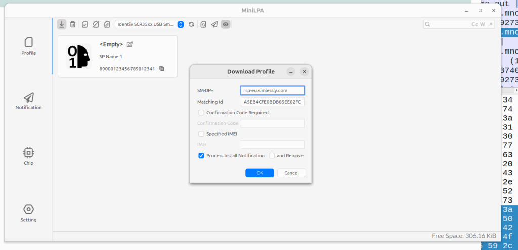
So in addition to this a SIM card reader I used a nifty util called MiniLPA which is the Local-Profile-Assistant, used to load eSIM profiles onto the eSIM itself.
I installed the Debian package of MiniLPA, started it up, plugged in my SIM reader and consume eUICC, then took the LPA address and split the SM-DP+ address (the Domain name part) and the ID (the long hex string part) up and plugged them into the download profile window and boom, I had a profile loaded and could work with the eSIM profile on a physical card.
The Network Repository Function is essentially a database used to store/query information about NFs on the network.
To do this, the NRF has 3 services: the Nnrf_NFManagement Service is used to insert/update/remove records into the database of NFs on the network, the Nrf_NFDiscovery service is used to query this database, and the OAuth2 Authorization service is used to authenticate / authorize the transactions of the first two securely.
The Nnrf_NFManagement Service
The Nnrf_NFManagement Service is the service that handles the registration, deregistration and updating the database of service-producing NFs.
When a NF offering a service becomes ready for service, it registers with the NRF to advise the NRF of the services it offers and so service-consumers (Clients) are able to find and then request services from this NF.
Let’s take a look at the NFRegister process, which is the service operation used to register an NF in the NRF.
At its heart, the NFRegister process is a HTTP2 PUT sent from the NF to the NRF to the path <nrf_ip>/nnrf-nfm/v1/nf-instances/{nrf-instance-id} with a JSON payload containing all the specifics of the services being offered by the NF (NFProfile), which is sent to the NRF.
The NRF parses through the message body (That JSON Payload containing the NFProfile) and adds all this info to the internal database in the NRF as to which service producers it has available.
If this is all OK from the NRF’s perspective, then a 200 OK is sent back by the NRF.
The NFProfile JSON body
The NFProfile is a JSON encoded message body that contains all the info about the NF that the NRF takes and adds to its internal database of services offered by that NF.
nfInstanceID – The Network Function Instance ID is the unique identity if this NF. (It’s also included in the Request URI) It’s a unique ID and typically generated randomly by the NF itself.
nfType – The type of the NF itself, there’s a long list of supported NF Types, NRF, UDM, AMF, SMF, AUSF, etc, etc.
nfStatus – Is the status of the NF, either REGISTERED (Discoverable by other NFs), SUSPENDED (Registered in the NRF but not able to be discovered / invisible, NFs in this state are usually here because they’ve had a high failure rate or haven’t been responding to heartbeats), UNDISCOVERABLE (Used when an NF wants to stop offering services to new consumers, but is still able to offer services to existing consumers, the idea being this is taking it out of the discovery pool, but still able to serve in-process requests).
plmnList – This is a list of PLMNs that this NF serves.
fqdn – The Fully Qualified Domain name of the NF
IPv4Address / IPv6Address – The IPv4 and/or IPv6 address of the NF
nfService – This is a list of JSON objects, detailing the services offered by the NF, such as the service names it is offering, version of the service, IDs of the service instances and IP Endpoints for requests to be sent to.
priority / capacity / load – Used for selection of this NF from the pool and the order of results returned
The Nnrf_NFManagement Service also includes a Subscription service, to allow NFs to subscribe to changes in state, for example getting a notification if a NF that was registered becomes deregistered.
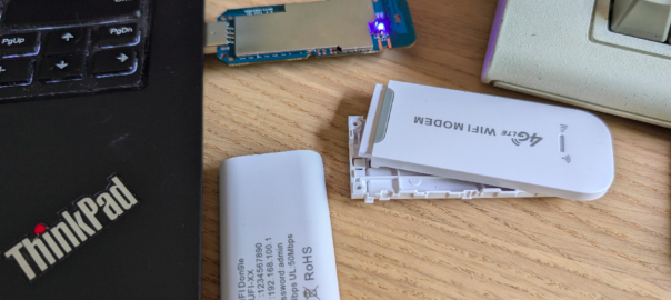
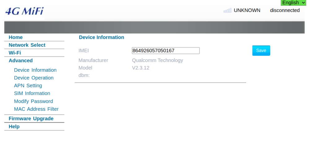
The device showed up as an rndis_host adapter in Linux, just like a USB NIC, and browsing to the default gateway shows a web UI where amazingly, you can set the IMEI – Pretty sure this isn’t legal…
This is not the IMEI it came with – that’s the IMEI of a EP06-e chip on my desk…
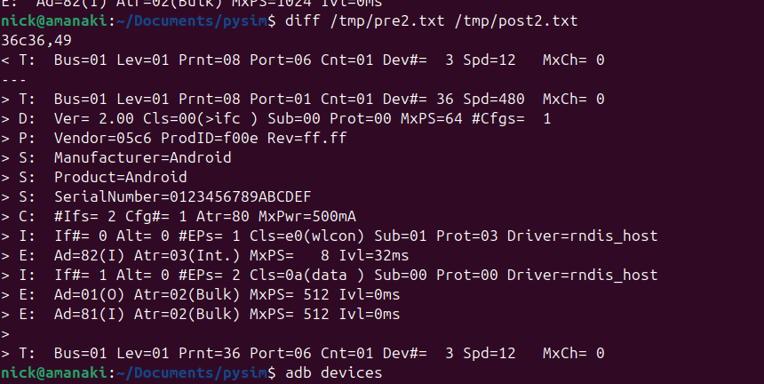
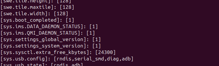
Oddly I could see it was an Android device, but with no adb port exposed, but wait – does that mean this an Android phone in a USB stick?
Alas no DIAG mode serial adapter showed up, despite a few variations on the above.
So with ADB connected could I stream the video from the device and use it like an Android phone?
You betcha:
After poking around in Android I found an App called “Qualcomm Settings” which piqued my interest.
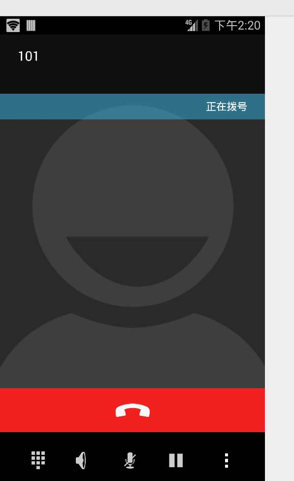
Alas the unit only supports LTE Band 1 / 3 / 5 none of which I have in my office (I’m too lazy to go out to the lab to fire up an Airscale) so I put a public SIM in it and was able to use data, but when I tried to make a call it seems it kicked off CS fallback.
More exploring to do, but pretty amazing what $10 buys you!
So we’ve found this scenario that occurs on some Samsung UEs, in certain radio contions, where midway through an otherwise normal voice call, the UE sends “mystery” data (Not IP data), which in turn causes the UPF to send the error indication and drop the bearer, which in turn drops the call.
The call starts, like any normal call, SIP REGISTER, INVITE, etc.
The P-CSCF / PCRF / PGW set up the dedicated bearer for the voice traffic, and the RTP stream starts flowing over it.
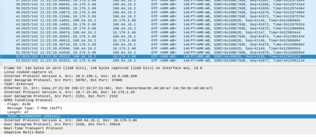
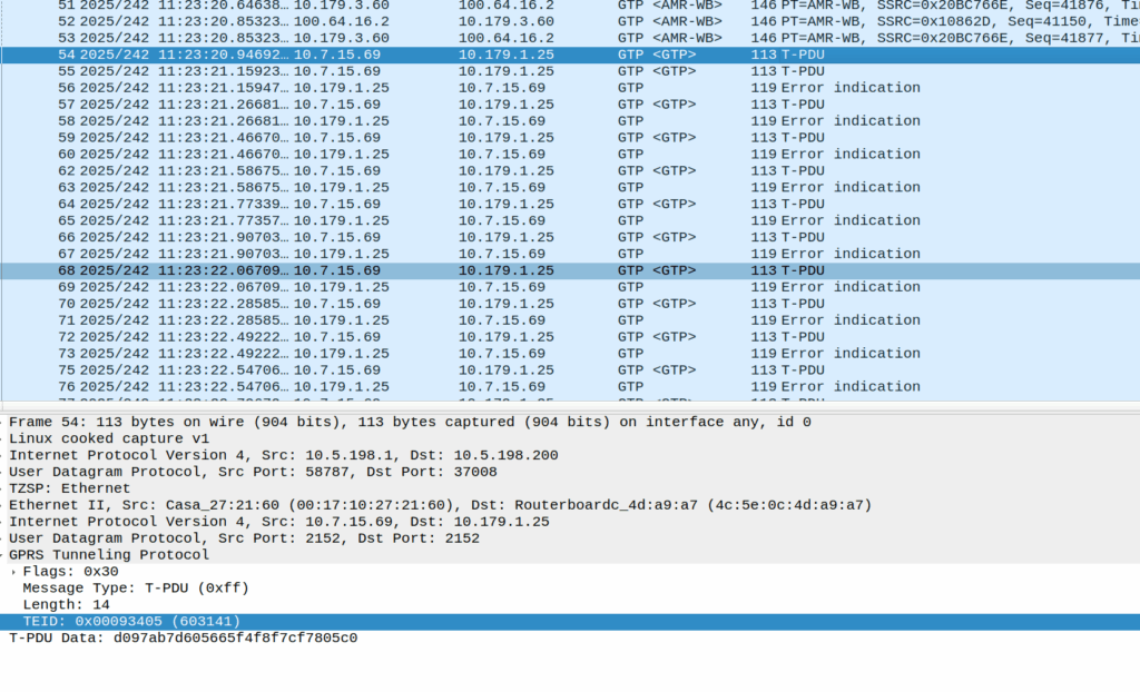
Then the UE sends these weird packets instead of the RTP stream:
These are GTP-U encapsulated data, with the TEID that matches the TEID used for the RTP stream, but there’s no IP data in them – they’re only 14 bytes long and sent by the UE.
Here’s some examples of what’s sent (each line is a packet):
An IPv4 header is 20 bytes long, and IPv6 header is 40, so this is too short for either of those protocols, but what else could it be?
There’s some commonality of course, starts d0 as the first octet, then d1, d2, d3, etc. So that’s something?
I thought perhaps it was a boundary issue, that the standard RTP packet was being split across multiple GTP-U payloads, but that doesn’t appear to be the case.
An Ethernet header is 14 bytes, but if we were to decode this as Ethernet there’s still nothing it’s transporting, and the destination MAC is changing sequentailly if that’s the case, which would be even weirder.
I also thought about RTP that for some reason has lost it’s IP/UDP header, as the sequentially counting byte at the start could be the RTP sequence number, but that’d be 19 bytes minimum and the sequence number is the 3rd and 4th byte, not the first.
Whatever they contain, we see this sent over and over for a few seconds, then bam, back to normal RTP stream flowing.
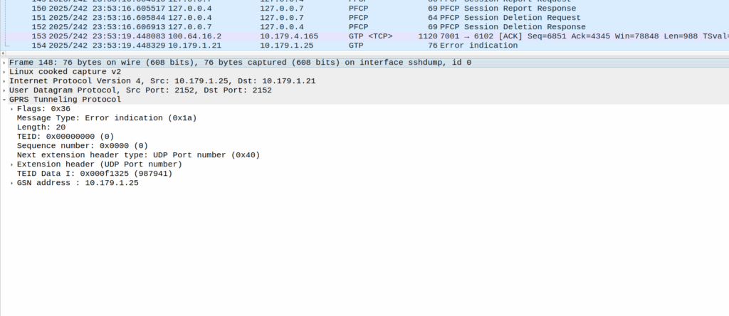
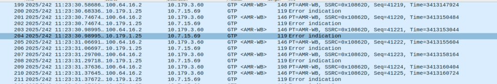
Or at least it should be, but the invalid packet causes the UPF to generate a GTP-U Error Indication.
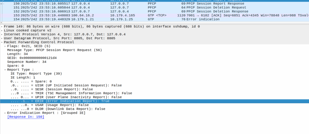
These Error Indication payloads eventually lead to the next PFCP Session Report Request having the Error Indication Report (ERIR) flag set to True.
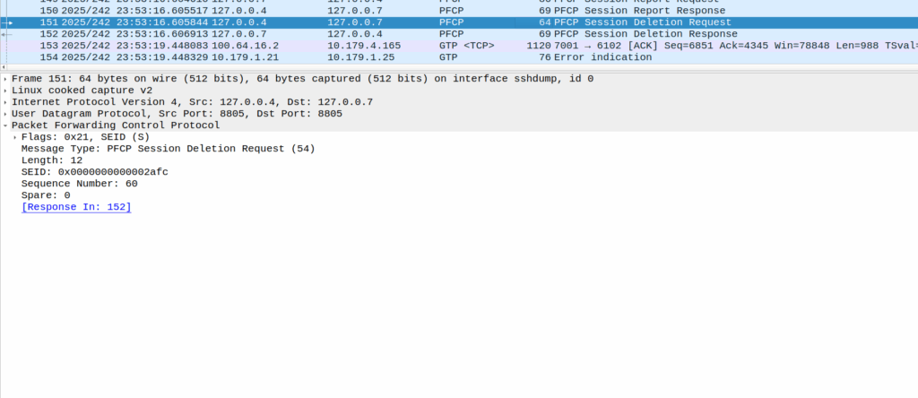
When the PGW-U gets this, it sends a Session Delete Request, which dutifully drops the bearer.
Meaning the session drops on the EPC side, and the RTP drops with it, eventually a BYE is sent from the phone due to RTP timeout.
The above screenshot shows a different cause of GTP-U Error Indication – At this point the bearer has been dropped on the EPC side and these are Error Indications to report it doesn’t know the TIED / bearer.
How to fix this?
Well, unlikely we’ll get a fix on the Samsung side, so we’ll need to not drop the bearer on the PGW-C if we get a lot of Error Indications, and hope for the best.
I started this blog when I got my first job – I was installing Nortel equipment. The name was meant as “Nick versus Networking”, as I attempted to take on the trade and learn it.
Going through CCNA, networking certs, I got way more into SIP/VoIP, I discovered Asterisk, which got me into FreeSWITCH, which eventually got me into Kamailio, all of which I wrote about as I went, as I learned stuff, I wrote it down. A few years later I somehow landed a job as “Senior Voice Engineer” for a carrier, in no small thanks to the blog, and built all the things; automated stuff with Ansible, pushed around data with Python and built production infra with FreeSWITCH and Kamailio, again, lots of posts around this time on those topics.
Eventually I got a bit bored at fixed line voice, so I made the move into Mobile, again, reflected in the blog posts.
I bought an eNodeB, built an HSS and got a functioning lab setup for 4G and VoLTE. That landed me a job at systems integrator working on packet core, then I moved to a solution architect role for one of the big RAN kit vendors looking for more challenges, but sadly I didn’t find enough challenges to keep me interested.
So I accidentally started a company (Omnitouch) and now find myself working with a bunch of super talented folks to build mobile networks in weird and wonderful parts of the planet.
All along I’ve been learning new stuff, and writing about it, and somewhere along the way, I found time to write 500 blog posts about all the bits I’ve learned as I went along, if you’ve been reading along, thanks, hopefully you found something interesting, and I’ll see you again at post number 1000 in another decade!
The UE Authentication Service is consumed by the AMF. The AMF initiates the authentication operation, when indicated, as part of the UE registration process. The AUSF performs either 5G-AKA or EAP-based authentication based on information received from the AMF. If EAP authentication is used then the AUSF and the UE exchange EAP messages through the AMF.
3GPP TS 29.509 V16.3.0; 5G System; Authentication Server Services
Common Dialogs on Nausf-auth Service
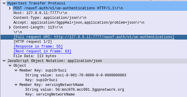
Authenticate UE – Request
HTTP POST sent from the AMF to the AUSF, to the URL /nausf-auth/v1/ue-authentications with JSON body containing the SUPI or the SUCI, and the serving network name.
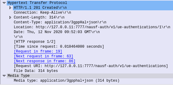
Authenticate UE – Response
If request from the AMF is successfully processed by the AUSF, it sends back a “201 Created” response, with a JSON Body containing the authentication vectors:
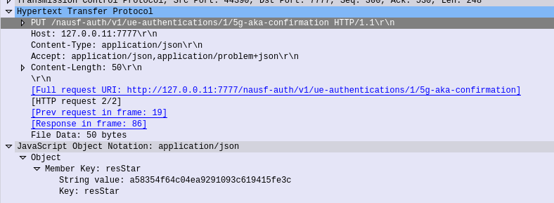
The AMF needs to advise the AUSF the RES returned from the Subscriber (if one was returned) to confirm the UE successfully authenticated, so the AMF sends this in the form of an HTTP PUT to the AUSF to the URL /nausf-auth/v1/ue-authentications/1/5g-aka-confirmation
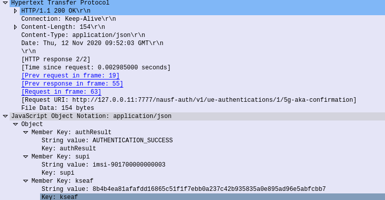
5G-AKA Confirmation – Response
If successful a 200 OK is sent back to the AMF by the AUSF with a JSON body containing the SUPI of the Subscriber (keep in mind the subscriber may have authenticated with a SUCI, so up until this point the AMF doesn’t know the SUPI of the Subscriber), and the Kseaf key used for ciphering and integrity protection.
Common Dialogs on Nudm-ueau Service
The Nudm_UEAuthentication service is used by NF service consumers to obtain UE authentication vectors from the UDM, to inform the UDM of authentication results, to query authentication results, and to purge authentication results.
3GPP TS 29.503 Unified Data Management Services
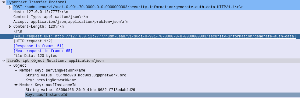
Generate Authentication Data – Request
When the AUSF needs to authenticate a subscriber, for example because an AMF has requested vectors, it in turn needs to request this information be generated by the UDM.
So the AUSF sends a HTTP POST to /nudm-ueau/v1/suci-0-901-70-0000-0-0-0000000003/security-information/generate-auth-data on the UDM (Where 901-70-0000-0-0-0000000003 is the SUPI or SUCI of the subscriber), and with a JSON body containing the AUSF’s Instance ID.
Generate Authentication Data – Response
Once the UDM has
The UDM will need to take the SUPI/SUCI provided by the AUSF and generate the authentication vectors following the AKA Process taking the OP/OPc & K keys as inputs.
The UDM sends a 200 OK back to the AUSF that requested the information, with a JSON Body containing the full vectors, including the Kausf to be provided to the AMF when the subscriber has successfully authenticated.
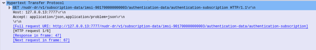
The AUSF sends an HTTP GET to the UDM with the SUPI/SUCI in the URI /nudr-dr/v1/subscription-data/imsi-901700000000003/authentication-data/authentication-subscription
To do this the UDM needs the K & OP (or OPc) values for that subscriber, depending on the UDM configuration, it may have this data cached, or it may need to retrieve these values from the UDR.