Tag Archives: Diameter

Credit Control Request / Answer call flow in IMS Charging

Basics of EPC/LTE Online Charging (OCS)

Early on as subscriber trunk dialing and automated time-based charging was introduced to phone networks, engineers were faced with a problem from Payphones.

Previously a call had been a fixed price, once the caller put in their coins, if they put in enough coins, they could dial and stay on the line as long as they wanted.

But as the length of calls began to be metered, it means if I put $3 of coins into the payphone, and make a call to a destination that costs $1 per minute, then I should only be allowed to have a 3 minute long phone call, and the call should be cutoff before the 4th minute, as I would have used all my available credit.

Conversely if I put $3 into the Payphone and only call a $1 per minute destination for 2 minutes, I should get $1 refunded at the end of my call.

We see the exact same problem with prepaid subscribers on IMS Networks, and it’s solved in much the same way.

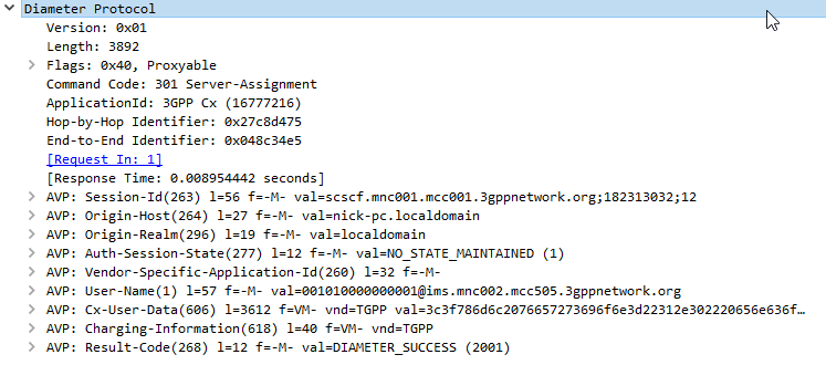
In LTE/EPC Networks, Diameter is used for all our credit control, with all online charging based on the Ro interface. So let’s take a look at how this works and what goes on.

Generic 3GPP Online Charging Architecture

3GPP defines a generic 3GPP Online charging architecture, that’s used by IMS for Credit Control of prepaid subscribers, but also for prepaid metering of data usage, other volume based flows, as well as event-based charging like SMS and MMS.

Network functions that handle chargeable services (like the data transferred through a P-GW or calls through a S-CSCF) contain a Charging Trigger Function (CTF) (While reading the specifications, you may be left thinking that the Charging Trigger Function is a separate entity, but more often than not, the CTF is built into the network element as an interface).

The CTF is a Diameter application that generates requests to the Online Charging Function (OCF) to be granted resources for the session / call / data flow, the subscriber wants to use, prior to granting them the service.

So network elements that need to charge for services in realtime contain a Charging Trigger Function (CTF) which in turn talks to an Online Charging Function (OCF) which typically is part of an Online Charging System (AKA OCS).

For example when a subscriber turns on their phone and a GTP session is setup on the P-GW/PCEF, but before data is allowed to flow through it, a Diameter “Credit Control Request” is generated by the Charging Trigger Function (CTF) in the P-GW/PCEF, which is sent to our Online Charging Server (OCS).

The “Credit Control Answer” back from the OCS indicates the subscriber has the balance needed to use data services, and specifies how much data up and down the subscriber has been granted to use.

The P-GW/PCEF grants service to the subscriber for the specified amount of units, and the subscriber can start using data.

This is a simplified example – Decentralized vs Centralized Rating and Unit Determination enter into this, session reservation, etc.

The interface between our Charging Trigger Functions (CTF) and the Online Charging Functions (OCF), is the Ro interface, which is a Diameter based interface, and is common not just for online charging for data usage, IMS Credit Control, MMS, value added services, etc.

3GPP define a reference online-charging interface, the Ro interface, and all the application-specific interfaces, like the Gy for billing data usage, build on top of the Ro interface spec.

Basic Credit Control Request / Credit Control Answer Process

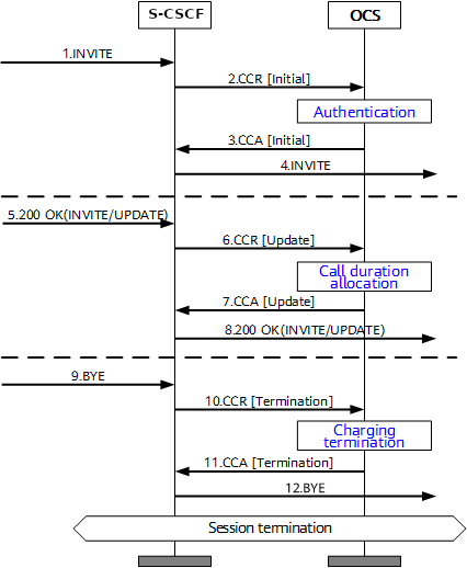
This example will look at a VoLTE call over IMS.

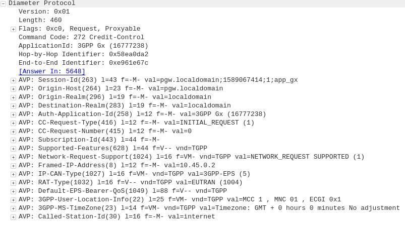
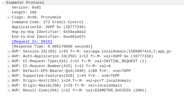
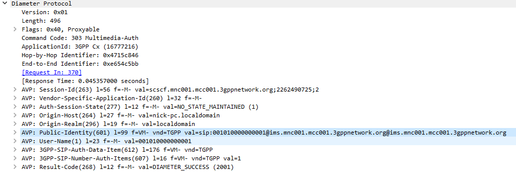
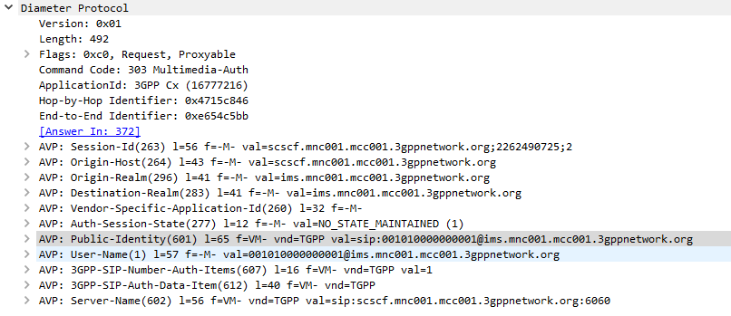
When a subscriber sends an INVITE, the Charging Trigger Function baked in our S-CSCF sends a Diameter “Credit Control Request” (CCR) to our Online Charging Function, with the type INITIAL, meaning this is the first CCR for this session.

The CCR contains the Service Information AVP. It’s this little AVP that is where the majority of the magic happens, as it defines what the service the subscriber is requesting. The main difference between the multitude of online charging interfaces in EPC networks, is just what the service the customer is requesting, and the specifics of that service.

For this example it’s a voice call, so this Service Information AVP contains a “IMS-Information” AVP. This AVP defines all the parameters for a IMS phone call to be online charged, for a voice call, this is the called-party, calling party, SDP (for differentiating between voice / video, etc.).

It’s the contents of this Service Information AVP the OCS uses to make decision on if service should be granted or not, and how many service units to be granted. (If Centralized Rating and Unit Determination is used, we’ll cover that in another post)
The actual logic, relating to this decision is typically based on the the rating and tariffing, credit control profiles, etc, and is outside the scope of the interface, but in short, the OCS will make a yes/no decision about if the subscriber should be granted access to the particular service, and if yes, then how many minutes / Bytes / Events should be granted.

In the received Credit Control Answer is received back from our OCS, and the Granted-Service-Unit AVP is analysed by the S-CSCF.
For a voice call, the service units will be time. This tells the S-CSCF how long the call can go on before the S-CSCF will need to send another Credit Control Request, for the purposes of this example we’ll imagine the returned value is 600 seconds / 10 minutes.

The S-CSCF will then grant service, the subscriber can start their voice call, and start the countdown of the time granted by the OCS.

As our chatty subscriber stays on their call, the S-CSCF approaches the limit of the Granted Service units from the OCS (Say 500 seconds used of the 600 seconds granted).
Before this limit is reached the S-CSCF’s CTF function sends another Credit Control Request with the type UPDATE_REQUEST. This allows the OCS to analyse the remaining balance of the subscriber and policies to tell the S-CSCF how long the call can continue to proceed for in the form of granted service units returned in the Credit Control Answer, which for our example can be 300 seconds.

Eventually, and before the second lot of granted units runs out, our subscriber ends the call, for a total talk time of 700 seconds.

But wait, the subscriber been granted 600 seconds for our INITIAL request, and a further 300 seconds in our UPDATE_REQUEST, for a total of 900 seconds, but the subscriber only used 700 seconds?

The S-CSCF sends a final Credit Control Request, this time with type TERMINATION_REQUEST and lets the OCS know via the Used-Service-Unit AVP, how many units the subscriber actually used (700 seconds), meaning the OCS will refund the balance for the gap of 200 seconds the subscriber didn’t use.

If this were the interface for online charging of data, we’d have the PS-Information AVP, or for online charging of SMS we’d have the SMS-Information, and so on.

The architecture and framework for how the charging works doesn’t change between a voice call, data traffic or messaging, just the particulars for the type of service we need to bill, as defined in the Service Information AVP, and the OCS making a decision on that based on if the subscriber should be granted service, and if yes, how many units of whatever type.

Diameter – Insert Subscriber Data Request / Response

While we’ve covered the Update Location Request / Response, where an MME is able to request subscriber data from the HSS, what about updating a subscriber’s profile when they’re already attached? If we’re just relying on the Update Location Request / Response dialog, the update to the subscriber’s profile would only happen when they re-attach.

We need a mechanism where the HSS can send the Request and the MME can send the response.

This is what the Insert Subscriber Data Request/Response is used for.

Let's imagine we want to allow a subscriber to access an additional APN, or change an AMBR values of an existing APN;

We'd send an Insert Subscriber Data Request from the HSS, to the MME, with the Subscription Data AVP populated with the additional APN the subscriber can now access.

Beyond just updating the Subscription Data, the Insert Subscriber Data Request/Response has a few other funky uses.

Through it the HSS can request the EPS Location information of a Subscriber, down to the TAC / eNB ID serving that subscriber. It’s not the same thing as the GMLC interfaces used for locating subscribers, but will wake Idle UEs to get their current serving eNB, if the Current Location Request is set in the IDR Flags.

But the most common use for the Insert-Subscriber-Data request is to modify the Subscription Profile, contained in the Subscription-Data AVP,

If the All-APN-Configurations-Included-Indicator is set in the AVP info, then all the existing AVPs will be replaced, if it’s not then everything specified is just updated.

The Insert Subscriber Data Request/Response is a bit novel compared to other S6a requests, in this case it’s initiated by the HSS to the MME (Like the Cancel Location Request), and used to update an existing value.

Diameter Agents

Let’s take a look at each of the common Diameter agent variants in use today:

Diameter Relay Agent / Diameter Routing Agent (DRA)

This is the simplest of the Diameter agents, but also probably the most common. The Diameter Relay agent does not look at the contents of the AVPs, it just routes messages based on the Application ID or Destination realm.

A Diameter Relay Agent does not change any AVPs except routing AVPs.

DRAs are transaction aware, but not dialog aware. This means they know if the Diameter request made it to the destination, but have no tracking of getting a response.

DRAs are common as a central hub for all Diameter hub in a network. This allows for a star topology where every Diameter service connects to a central DRA (typically two DRAs for redundancy) for a central place to manage Diameter routing, instead of having to do a full-mesh topology, which would be a nightmare on larger networks.

I recently wrote about creating a simple but unstable DRA with Kamailio.

Diameter Edge Agent

A Diameter Edge Agent is a special DRA that sits on the border between two networks and acts as a gateway between them.

Imagine a roaming exchange scenario, where each operator has to expose their core Diameter servers or DRAs to all the other operators they have roaming agreements with. Like we saw with the DRA to do a full-mesh style connection arrangement would be a mess, and wouldn’t allow internal changes inside the network without significant headaches.

Instead by putting a Diameter Edge Agent at the edge of the network, the operators who wish to access our Diameter information for roaming, only need to connect to a single point, and we can change whatever we like on the inside of the network, adding and removing servers, without having to update our roaming information (IR 21).

We can also strictly enforce security policies on rate limits and admission control, centrally, for all connections in from other operators.

Diameter Proxy Agent

The Diameter Proxy Agent does everything a DRA does, and more!

The Diameter Proxy Agent is application aware, meaning it can decode the AVPs and make decisions based upon the contents of the AVPs. It’s also able to edit / add / delete AVPs and Sub-AVPs.

These are useful for interconnect scenarios where you might need to re-write the value of an AVP, or translate a realm etc, on a Diameter request/response journey.

Diameter Translation Agent

Diameter Translation agents are used for translating between protocols, for example Diameter into MAP for GSM authentication, or into HTTP for 5G authentication.

For 5GC a new network element – the “Binding Support Function” (BSF) is introduced to translate between HTTP for 5G and Diameter for LTE, however this can be thought of as another Diameter Translation Agent.

SCTP Parameter Tuning

There’s a lot to like about SCTP. No head of line blocking, MTU issues, sequenced, acknowledged delivery of messages, not to mention Multi-Homing and message bundling.

But if you really want to get the most bang for your buck, you’ll need to tune your SCTP parameters to match the network conditions.

While tuning the parameters per-association would be time consuming, most SCTP stacks allow you to set templates for SCTP parameters, for example you would have a different set of parameters for the SCTP stacks inside your network, compared to SCTP stacks for say a roaming scenario or across microwave links.

IETF kindly provides a table with their recommended starting values for SCTP parameter tuning:

RTO.Initial3 seconds
RTO.Min1 second
RTO.Max60 seconds
Max.Burst4
RTO.Alpha1/8
RTO.Beta1/4
Valid.Cookie.Life60 seconds
Association.Max.Retrans10 attempts
Path.Max.Retrans5 attempts (per destination address)
Max.Init.Retransmits8 attempts
HB.interval30 seconds
HB.Max.Burst1
IETF – RFC4960: SCTP – Suggested Protocol Parameter Values

But by adjusting the Max Retrans and Retransmission Timeout (RTO) values, we can detect failures on the network more quickly, and reduce the number of packets we’ll loose should we have a failure.

We begin with the engineered round-trip time (RTT) – that is made up of the time it takes to traverse the link, processing time for the remote SCTP stack and time for the response to traverse the link again. For the examples below we’ll take an imaginary engineered RTT of 200ms.

RTO.min is the minimum retransmission timeout.
If this value is set too low then before the other side has had time to receive the request, process it and send a response, we’ve already retransmitted it.

This should be set to the round trip delay plus processing needed to send and acknowledge a packet plus some allowance for variability due to jitter; a value of 1.15 times the Engineered RTT is often chosen

So for us, 200 * 1.15 = 230ms RTO.min value.

RTO.max is the maximum amount of time we should wait before transmitting a request.
Typically three times the Engineered RTT.

So for us, 200 * 3 = 600ms RTO.min value.

Path.Max.Retransmissions is the maximum number of retransmissions to be sent down a path before the path is considered to be failed.
For example if we loose a transmission path on a multi-homed server, how many retransmissions along that path should we send until we consider it to be down?

Values set are dependant on if you’re multi-homing or not (you can be more picky if you are) and the level of acceptable packet loss in your transmission link.

Typical values are 4 Retransmissions (per destination address) for a Single-Homed association, and 2 Retransmissions (per destination address) for a Multi-Homed association.

Association.Max.Retransmissions is the maximum number of retransmissions for an association. If a transmission link in a multi-homed SCTP scenario were to go down, we would pass the Path.Max.Retransmissions value and the SCTP stack would stop sending traffic out that path, and try another, but what if the remote side is down? In that scenario all our paths would fail, so we need another counter – Path.Max.Retransmissions to count the total number of retransmissions to an association / destination. When the Association.Max.Retransmissions is reached the association is considered down.

In practice this value would be the number of paths, multiplied by the Path.Max.Retransmissions.

IMS Routing with iFCs

SIP routing is complicated, there’s edge cases, traffic that can be switched locally and other traffic that needs to be proxied off to another Proxy or Application server. How can you define these rules and logic in a flexible way, that allows these rules to be distributed out to multiple different network elements and adjusted on a per-subscriber basis?

Enter iFCs – The Initial Filter Criteria.

iFCs are XML encoded rules to define which servers should handle traffic matching a set of rules.

Let’s look at some example rules we might want to handle through iFCs:

  • Send all SIP NOTIFY, SUBSCRIBE and PUBLISH requests to a presence server
  • Any Mobile Originated SMS to an SMSc
  • Calls to a specific destination to a MGC
  • Route any SIP INVITE requests with video codecs present to a VC bridge
  • Send calls to Subscribers who aren’t registered to a Voicemail server
  • Use 3rd party registration to alert a server that a Subscriber has registered

All of these can be defined and executed through iFCs, so let’s take a look,

iFC Structure

iFCs are encoded in XML and typically contained in the Cx-user-data AVP presented in a Cx Server Assignment Answer response.

Let’s take a look at an example iFC and then break down the details as to what we’re specifying.

<InitialFilterCriteria>
    <Priority>10</Priority>
    <TriggerPoint>
        <ConditionTypeCNF>1</ConditionTypeCNF>
        <SPT>
            <ConditionNegated>0</ConditionNegated>
            <Group>0</Group>
            <Method>MESSAGE</Method>
        </SPT>
        <SPT>
            <ConditionNegated>0</ConditionNegated>
            <Group>1</Group>
            <SessionCase>0</SessionCase>
        </SPT>
    </TriggerPoint>
    <ApplicationServer>
        <ServerName>sip:smsc.mnc001.mcc001.3gppnetwork.org:5060</ServerName>
        <DefaultHandling>0</DefaultHandling>
    </ApplicationServer>
</InitialFilterCriteria>

Each rule in an iFC is made up of a Priority, TriggerPoint and ApplicationServer.

So for starters we’ll look at the Priority tag.
The Priority tag allows us to have multiple-tiers of priority and multiple levels of matching,
For example if we had traffic matching the conditions outlined in this rule (TriggerPoint) but also matching another rule with a lower priority, the lower priority rule would take precedence.

Inside our <TriggerPoint> tag contains the specifics of the rules and how the rules will be joined / matched, which is what we’ll focus on predominantly, and is followed by the <ApplicationServer> which is where we will route the traffic to if the TriggerPoint is matched / triggered.

So let’s look a bit more about what’s going on inside the TriggerPoint.

Each TriggerPoint is made up of Service Point Trigger (SPTs) which are individual rules that are matched or not matched, that are either combined as logical AND or logical OR statements when evaluated.

By using fairly simple building blocks of SPTs we can create a complex set of rules by joining them together.

Service Point Triggers (SPTs)

Let’s take a closer look at what goes on in an SPT.
Below is a simple SPT that will match all SIP requests using the SIP MESSAGE method request type:

        <SPT>
            <ConditionNegated>0</ConditionNegated>
            <Group>0</Group>
            <Method>MESSAGE</Method>
        </SPT>

So as you may have guessed, the <Method> tag inside the SPT defines what SIP request method we’re going to match.

But Method is only one example of the matching mechanism we can use, but we can also match on other attributes, such as Request URI, SIP Header, Session Case (Mobile Originated vs Mobile Terminated) and Session Description such as SDP.

Or an example of a SPT for anything Originating from the Subscriber utilizing the <SessionCase> tag inside the SPT.

        <SPT>
            <ConditionNegated>0</ConditionNegated>
            <Group>0</Group>
            <SessionCase>0</SessionCase>
        </SPT>

Below is another SPT that’s matching any requests where the request URI is sip:[email protected] by setting the <RequestURI> tag inside the SPT:

        <SPT>
            <ConditionNegated>0</ConditionNegated>
            <Group>0</Group>
            <RequestURI>sip:[email protected]</RequestURI>
        </SPT>

We can match SIP headers, either looking for the existence of a header or the value it is set too,

        <SPT>
            <ConditionNegated>0</ConditionNegated>
            <Group>0</Group>
            <SIPHeader>
              <Header>To</Header>
              <Content>"Nick"</Content>
            </SIPHeader>
        </SPT>

Having <Header> will match if the header is present, while the optional Content tag can be used to match

In terms of the Content this is matched using Regular Expressions, but in this case, not so regular regular expressions. 3GPP selected Extended Regular Expressions (ERE) to be used (IEEE POSIX) which are similar to the de facto standard PCRE Regex, but with a few fewer parameters.

Condition Negated

The <ConditionNegated> tag inside the SPT allows us to do an inverse match.

In short it will match anything other than what is specified in the SPT.

For example if we wanted to match any SIP Methods other than MESSAGE, setting <ConditionNegated>1</ConditionNegated> would do just that, as shown below:

        <SPT>
            <ConditionNegated>1</ConditionNegated>
            <Group>0</Group>
            <Method>MESSAGE</Method>
        </SPT>

And another example of ConditionNegated in use, this time we’re matching anything where the Request URI is not sip:[email protected]:

        <SPT>
            <ConditionNegated>1</ConditionNegated>
            <Group>0</Group>
            <RequestURI>sip:[email protected]</RequestURI>
        </SPT>

Finally the <Group> tag allows us to group together a group of rules for the purpose of evaluating.
We’ll go into it more in in the below section.

ConditionTypeCNF / ConditionTypeDNF

As we touched on earlier, <TriggerPoints> contain all the SPTs, but also, very importantly, specify how they will be interpreted.

SPTs can be joined in AND or OR conditions.

For some scenarios we may want to match where METHOD is MESSAGE and RequestURI is sip:[email protected], which is different to matching where the METHOD is MESSAGE or RequestURI is sip:[email protected].

This behaviour is set by the presence of one of the ConditionTypeCNF (Conjunctive Normal Form) or ConditionTypeDNF (Disjunctive Normal Form) tags.

If each SPT has a unique number in the GroupTag and ConditionTypeCNF is set then we evaluate as AND.

If each SPT has a unique number in the GroupTag and ConditionTypeDNF is set then we evaluate as OR.

Let’s look at how the below rule is evaluated as AND as ConditionTypeCNF is set:

<InitialFilterCriteria>
    <Priority>10</Priority>
    <TriggerPoint>
        <ConditionTypeCNF>1</ConditionTypeCNF>
        <SPT>
            <ConditionNegated>0</ConditionNegated>
            <Group>0</Group>
            <Method>MESSAGE</Method>
        </SPT>
        <SPT>
            <ConditionNegated>0</ConditionNegated>
            <Group>1</Group>
            <SessionCase>0</SessionCase>
        </SPT>
    </TriggerPoint>
    <ApplicationServer>
        <ServerName>sip:smsc.mnc001.mcc001.3gppnetwork.org:5060</ServerName>
        <DefaultHandling>0</DefaultHandling>
    </ApplicationServer>
</InitialFilterCriteria>

This means we will match if the method is MESSAGE and Session Case is 0 (Mobile Originated) as each SPT is in a different Group which leads to “and” behaviour.

If we were to flip to ConditionTypeDNF each of the SPTs are evaluated as OR.

<InitialFilterCriteria>
    <Priority>10</Priority>
    <TriggerPoint>
        <ConditionTypeDNF>1</ConditionTypeDNF>
        <SPT>
            <ConditionNegated>0</ConditionNegated>
            <Group>0</Group>
            <Method>MESSAGE</Method>
        </SPT>
        <SPT>
            <ConditionNegated>0</ConditionNegated>
            <Group>1</Group>
            <SessionCase>0</SessionCase>
        </SPT>
    </TriggerPoint>
    <ApplicationServer>
        <ServerName>sip:smsc.mnc001.mcc001.3gppnetwork.org:5060</ServerName>
        <DefaultHandling>0</DefaultHandling>
    </ApplicationServer>
</InitialFilterCriteria>

This means we will match if the method is MESSAGE and Session Case is 0 (Mobile Originated).

Where this gets a little bit more complex is when we have multiple entries in the same Group tag.

Let’s say we have a trigger point made up of:

<SPT><Method>MESSAGE</Method><Group>1</Group></SPT>
<SPT><SessionCase>0</SessionCase><Group>1</Group></SPT> 

<SPT><Header>P-Some-Header</Header><Group>2</Group></SPT> 

How would this be evaluated?

If we use ConditionTypeDNF every SPT inside the same Group are matched as AND, and SPTs with distinct are matched as OR.

Let’s look at our example rule evaluated as ConditionTypeDNF:

<ConditionTypeDNF>1</ConditionTypeDNF>
  <SPT><Method>MESSAGE</Method><Group>1</Group></SPT>
  <SPT><SessionCase>0</SessionCase><Group>1</Group></SPT> 

  <SPT><Header>P-Some-Header</Header><Group>2</Group></SPT> 

This means the two entries in Group 1 are evaluated as AND – So Method is message and Session Case is 0, OR the header “P-Some-Header” is present.

Let’s do another one, this time as ConditionTypeCNF:

<ConditionTypeCNF>1</ConditionTypeCNF>
  <SPT><Method>MESSAGE</Method><Group>1</Group></SPT>
  <SPT><SessionCase>0</SessionCase><Group>1</Group></SPT> 

  <SPT><Header>P-Some-Header</Header><Group>2</Group></SPT> 

This means the two entries in Group 1 are evaluated as OR – So Method is message OR Session Case is 0, AND the header “P-Some-Header” is present.

Diameter Droplets – The Flow-Description AVP and IPFilterRules

When it comes to setting up dedicated bearers, the Flow-Description AVP is perhaps the most important,

The specially encoded string (IPFilterRule) in the FlowDescription AVP is what our P-GW (Ok, our PCEF) uses to create Traffic Flow Templates to steer certain types of traffic down Dedicated Bearers.

So let’s take a look at how we can lovingly craft an artisanal Flow-Description.

The contents of the AVP are technically not a string, but a IPFilterRule.

IPFilterRules are actually defined in the Diameter Base Protocol (IETF RFC 6733), where we can learn the basics of encoding them,

Which are in turn based loosely off the ipfw utility in BSD.

They take the format:

action dir proto from src to dst

The action is fairly simple, for all our Dedicated Bearer needs, and the Flow-Description AVP, the action is going to be permit. We’re not blocking here.

The direction (dir) in our case is either in or out, from the perspective of the UE.

Next up is the protocol number (proto), as defined by IANA, but chances are you’ll be using 17 (UDP) or 6 (TCP) in most scenarios.

The from value is followed by an IP address with an optional subnet mask in CIDR format, for example from 10.45.0.0/16 would match everything in the 10.45.0.0/16 network.
Following from you can also specify the port you want the rule to apply to, or, a range of ports,
For example to match a single port you could use 10.45.0.0/16 1234 to match anything on port 1234, but we can also specify ranges of ports like 10.45.0.0/16 0 – 4069 or even mix and match lists and single ports, like 10.45.0.0/16 5060, 1000-2000

Protip: using any is the same as 0.0.0.0/0

Like the from, the to is encoded in the same way, with either a single IP, or a subnet, and optional ports specified.

And that’s it!

Keep in mind that Flow-Descriptions are typically sent in pairs as a minimum, as you want to match the traffic into and out of the network (not just one way), but often there can be quite a few sent, in order to match all the possible traffic that needs to be matched that may be across multiple different subnets, etc.

There is an optional Options parameter that allows you to set things like to only apply the rule to open TCP sessions, fragmentation, etc, although I’ve not seen this implemented in the wild.

Example IP filter Rules

permit in 6 from 10.98.254.0/24 5061 to 10.98.0.0/24 5060
permit out 6 from 10.98.254.0/24 5060 to 10.98.0.0/24 5061

permit in 6 from any 80 to 172.16.1.1 80
permit out 6 from 172.16.1.1 80 to any 80

permit in 17 from 10.98.254.0/24 50000-60100 to 10.98.0.0/24 50000-60100
permit out 17 from 10.98.254.0/24 50000-60100 to 10.98.0.0/24 50000-60100

permit in 17 from 10.98.254.0/24 5061, 5064 to 10.98.0.0/24  5061, 5064
permit out 17 from 10.98.254.0/24 5061, 5064 to 10.98.0.0/24  5061, 5064

permit in 17 from 172.16.0.0/16 50000-60100, 5061, 5064 to 172.16.0.0/16  50000-60100, 5061, 5064
permit out 17 from 172.16.0.0/16 50000-60100, 5061, 5064 to 172.16.0.0/16  50000-60100, 5061, 5064

For more info see:

RFC 6773 – Diameter Base Protocol – IP Filter Rule

3GPP TS 29.214 section 5.3.8 Flow-Description AVP

A very unstable Diameter Routing Agent (DRA) with Kamailio

I’d been trying for some time to get Kamailio acting as a Diameter Routing Agent with mixed success, and eventually got it working, after a few changes to the codebase of the ims_diameter_server module.

It is rather unstable, in that if it fails to dispatch to a Diameter peer, the whole thing comes crumbling down, but incoming Diameter traffic is proxied off to another Diameter peer, and Kamailio even adds an extra AVP.

Having used Kamailio for so long I was really hoping I could work with Kamailio as a DRA as easily as I do for SIP traffic, but it seems the Diameter module still needs a lot more love before it’ll be stable enough and simple enough for everyone to use.

I created a branch containing the fixes I made to make it work, and with an example config for use, but use with caution. It’s a long way from being production-ready, but hopefully in time will evolve.

https://github.com/nickvsnetworking/kamailio/tree/Diameter_Fix

MSISDN Encoding - Brought to you by the letter F

MSISDN Encoding in Diameter AVPs – Brought to you by the letter F

So this one knocked me for six the other day,

MSISDN AVP 700 / vendor ID 10415, used to advertise the subscriber’s MSISDN in signaling.

I formatted the data as an Octet String, with the MSISDN from the database and moved on my merry way.

Not so fast…

The MSISDN AVP is of type OctetString.

This AVP contains an MSISDN, in international number format as described in ITU-T Rec E.164 [8], encoded as a TBCD-string, i.e. digits from 0 through 9 are encoded 0000 to 1001;

1111 is used as a filler when there is an odd number of digits; bits 8 to 5 of octet n encode digit 2n; bits 4 to 1 of octet n encode digit 2(n-1)+1.

ETSI TS 129 329 / 6.3.2 MSISDN AVP

Come again?

In practice this means if you have an odd lengthed MSISDN value, we need to add some padding to round it out to an even-lengthed value.

This padding happens between the last and second last digit of the MSISDN (because if we added it at the start we’d break the Country Code, etc) and as MSISDNs are variable length subscriber numbers.

1111 in octet string is best known as the letter F,

Not that complicated, just kind of confusing.

PyHSS Update – SCTP Support

Pleased to announce that PyHSS now supports SCTP for transport.

If you’re not already aware SCTP is the surprisingly attractive cousin of TCP, that addresses head of line blocking and enables multi-homing,

The fantastic PySCTP library from P1sec made adding this feature a snap. If you’re looking to add SCTP to a Python project, it’s surprisingly easy,

A seperate server (hss_sctp.py) is run to handle SCTP connections, and if you’re looking for Multihoming, we got you dawg – Just edit the config file and set the bind_ip list to include each of your IPs to multi home listen on.

And the call was coming from… INSIDE THE HOUSE. A look at finding UE Locations in LTE

Opening Tirade

Ok, admittedly I haven’t actually seen “When a Stranger Calls”, or the less popular sequel “When a stranger Redials” (Ok may have made the last one up).

But the premise (as I read Wikipedia) is that the babysitter gets the call on the landline, and the police trace the call as originating from the landline.

But you can’t phone yourself, that’s not how local loops work – When the murderer goes off hook it loops the circuit, which busys it. You could apply ring current to the line I guess externally but unless our murder has a Ring generator or has setup a PBX inside the house, the call probably isn’t coming from inside the house.

On Topic – The GMLC

The GMLC (Gateway Mobile Location Centre) is a central server that’s used to locate subscribers within the network on different RATs (GSM/UMTS/LTE/NR).

The GMLC typically has interfaces to each of the radio access technologies, there is a link between the GMLC and the CS network elements (used for GSM/UMTS) such as the HLR, MSC & SGSN via Lh & Lg interfaces, and a link to the PS network elements (LTE/NR) via Diameter based SLh and SLg interfaces with the MME and HSS.

The GMLC’s tentacles run out to each of these network elements so it can query them as to a subscriber’s location,

LTE Call Flow

To find a subscriber’s location in LTE Diameter based signaling is used, to query the MME which in turn queries, the eNodeB to find the location.

But which MME to query?

The SLh Diameter interface is used to query the HSS to find out which MME is serving a particular Subscriber (identified by IMSI or MSISDN).

The LCS-Routing-Info-Request is sent by the GMLC to the HSS with the subscriber identifier, and the LCS-Routing-Info-Response is returned by the HSS to the GMLC with the details of the MME serving the subscriber.

Now we’ve got the serving MME, we can use the SLg Diameter interface to query the MME to the location of that particular subscriber.

The MME can report locations to the GMLC periodically, or the GMLC can request the MME provide a location at that point.
For the GMLC to request a subscriber’s current location a Provide-Location-Request is set by the GMLC to the MME with the subscriber’s IMSI, and the MME responds after querying the eNodeB and optionally the UE, with the location info in the Provide-Location-Response.

(I’m in the process of adding support for these interfaces to PyHSS and all going well will release some software shortly to act at a GMLC so people can use this.)

Finding the actual Location

There are a few different ways the actual location of the UE is determined,

At the most basic level, Cell Global Identity (CGI) gives the identity of the eNodeB serving a user.
If you’ve got a 3 sector site each sector typically has its own Cell Global Identity, so you can determine to a certain extent, with the known radiation pattern, bearing and location of the sector, in which direction a subscriber is. This happens on the network side and doesn’t require any input from the UE.
But if we query the UE’s signal strength, this can then be combined with existing RF models and the signal strength reported by the UE to further pinpoint the user with a bit more accuracy. (Uplink and downlink cell coverage based positioning methods)
Barometric pressure and humidity can also be reported by the base station as these factors will impact resulting signal strengths.

Timing Advance (TA) and Time of Arrival (TOA) both rely on timing signals to/from a UE to determine it’s distance from the eNodeB. If the UE is only served by a single cell this gives you a distance from the cell and potentially an angle inside which the subscriber is. This becomes far more useful with 3 or more eNodeBs in working range of the UE, where you can “triangulate” the UE’s location. This part happens on the network side with no interaction with the UE.
If the UE supports it, EUTRAN can uses Enhanced Observed Time Difference (E-OTD) positioning method, which does TOD calcuation does this in conjunction with the UE.

GPS Assisted (A-GPS) positioning gives good accuracy but requires the devices to get it’s current location using the GPS, which isn’t part of the baseband typically, so isn’t commonly implimented.

Uplink Time Difference of Arrival (UTDOA) can also be used, which is done by the network.

So why do we need to get Subscriber Locations?

The first (and most noble) use case that springs to mind is finding the location of a subscriber making a call to emergency services. Often upon calling an emergency services number the GMLC is triggered to get the subscriber’s location in case the call is cut off, battery dies, etc.

But GMLCs can also be used for lots of other purposes, marketing purposes (track a user’s location and send targeted ads), surveillance (track movements of people) and network analytics (look at subscriber movement / behavior in a specific area for capacity planning).

Different countries have different laws regulating access to the subscriber location functions.

Hack to disable Location Reporting on Mobile Networks

If you’re wondering how you can disable this functionality, you can try the below hack to ensure that your phone does not report your location.

  1. Press the power button on your phone
  2. Turn it off

In reality, no magic super stealth SIM cards, special phones or fancy firmware will prevent the GMLC from finding your location.
So far none of the “privacy” products I’ve looked at have actually done anything special at the Baseband level. Most are just snakeoil.

For as long as your device is connected to the network, the passive ways of determining location, such as Uplink Time Difference of Arrival (UTDOA) and the CGI are going to report your location.

PyHSS New Features

Thanks to some recent developments, PyHSS has had a major overhaul recently, and is getting better than ever,

Some features that are almost ready for public release are:

Config File

Instead of having everything defined all over the place a single YAML config file is used to define how the HSS should function.

SCTP Support

No longer just limited to TCP, PyHSS now supports SCTP as well for transport,

SLh Interface for Location Services

So the GMLC can query the HSS as to the serving MME of a subscriber.

Additional Database Backends (MSSQL & MySQL)

No longer limited to just MongoDB, simple functions to add additional backends too and flexible enough to meet your existing database schema.

All these features will be merged into the mainline soon, and documented even sooner. I’ll share some posts on each of these features as I go.

Diameter Dispatches: S6a Authentication Information Request / Answer

This is part of a series of posts focusing on common Diameter request pairs, looking at what’s inside and what they do.

The Authentication Information Request (AIR) and Authentication Information Answer (AIA) are one of the first steps in authenticating a subscriber, and a very common Diameter transaction.

The Process

The Authentication Information Request (AIR) is sent by the MME to the HSS to request when a Subscriber begins to attach containing the IMSI of the subscriber trying to connect.

If the subscriber’s IMSI is known to the HSS, the AuC will generate Authentication Vectors for the Subscriber, and repond back to the MME in an Authentication Information Answer (AIA).

For more information on how the Authentication process works and what the authentication vectors do, I’ve written about that quite extensively here.- HSS & USIM Authentication in LTE.

The Authentication Information Request (AIR)

The AIR is a comparatively simple request, without many AVPs;

The Session-Id, Auth-Session-State, Origin-Host, Origin-Realm & Destination-Realm are all common AVPs that have to be included.

The Username AVP (AVP 1) contains the username of the subscriber, which in this case is the IMSI.

The Requested-EUTRAN-Authentication-Info AVP ( AVP 1408 ) contains information in regards to what authentication info the MME is requesting from the subscriber, typically this indicates the MME is requesting 1 vector (Number-Of-Requested-Vectors (AVP 1410)), an immediate response is preferred (Immediate-Response-Preferred (AVP 1412)), and if the subscriber is re-resyncing the SQN will include a Re-Synchronization-Info AVP (AVP 1411).

The Visited-PLMN-Id AVP (AVP 1407) contains information regarding the PLMN of the RAN the Subscriber is connecting to.

The Authentication Information Answer (AIA)

The Authentication Information Answer contains several mandatory AVPs that would be expected, The Session-Id, Auth-Session-State, Origin-Host and Origin-Realm.

The Result Code (AVP 268) indicates if the request was successful or not, 2001 indicates DIAMETER SUCCESS.

The Authentication-Info (AVP 1413) contains the returned vectors, in LTE typically only one vector is returned, a sub AVP called E-UTRAN-Vector (AVP 1414), which contains AVPs with the RAND, XRES, AUTN and KASME keys.

Further Reading & References

3GPP TS 29.272 version 15.10.0 Release 15

Example Packet Capture (PCAP) of Message Flow

Diameter Dispatches – Origin-State-Id AVP

The Origin-State-Id AVP solves a kind of tricky problem – how do you know if a Diameter peer has restarted?

It seems like a simple problem until you think about it.
One possible solution would be to add an AVP for “Recently Rebooted”, to be added on the first command queried of it from an endpoint, but what if there are multiple devices connecting to a Diameter endpoint?

The Origin-State AVP is a strikingly simple way to solve this problem. It’s a constantly incrementing counter that resets if the Diameter peer restarts.

If a client receives a Answer/Response where the Origin-State AVP is set to 10, and then the next request it’s set to 11, then the one after that is set to 12, 13, 14, etc, and then a request has the Origin-State AVP set to 5, the client can tell when it’s restarted by the fact 5 is lower than 14, the one before it.

It’s a constantly incrementing counter, that allows Diameter peers to detect if the endpoint has restarted.

Simple but effective.

You can find more about this in RFC3588 – the Diameter Base Protocol.

LTE UE Attach Procedures in Evolved Packet Core (EPC)

There’s a lot of layers of signalling in the LTE / EUTRAN attach procedure, but let’s take a look at the UE attach procedure from the Network Perspective.

We won’t touch on the air interface / Uu side of things, just the EPC side of the signaling.

To make life a bit easier I’ve put different signalling messages in different coloured headings:

Blue is S1AP

Orange is Diameter

Green is GTP-C (GTP-v2)

S1AP: initiating Message, Attach Request, PDN Connectivity Request

eNB to MME

After a UE establishes a connection with a cell, the first step involved in the attach process is for the UE / subscriber to identify themselves and the network to authenticate them.

The TAI, EUTRAN-CGI and GUMME-ID sections all contain information about the serving network, such the tracking area code, cell global identifier and global MME ID to make up the GUTI.

The NAS part of this request contains key information about our UE and it’s capabilities, most importantly it includes the IMSI or TMSI of the subscriber, but also includes important information such as SRVCC support, different bands and RAN technologies it supports, codecs, but most importantly, the identity of the subscriber.

If this is a new subscriber to the network, the IMSI is sent as the subscriber identity, however wherever possible sending the IMSI is avoided, so if the subscriber has connected to the network recently, the M-TMSI is used instead of the IMSI, and the MME has a record of which M-TMSI to IMSI mapping it’s allocated.

Diameter: Authentication Information Request

MME to HSS

The MME does not have a subscriber database or information on the Crypto side of things, instead this functionality is offloaded to the HSS.

I’ve gone on and on about LTE UE/Subscriber authentication, so I won’t go into the details as to how this mechanism works, but the MME will send a Authentication-Information Request via Diameter to the HSS with the Username set to the Subscriber’s IMSI.

Diameter: Authentication Information Response

HSS to MME

Assuming the subscriber exists in the HSS, a Authentication-Information Answer will be sent back from the HSS via Diameter to the MME, containing the authentication vectors to send to the UE / subscriber.

S1AP: DownlinkNASTransport, Authentication request

MME to eNB

Now the MME has the Authentication vectors for that UE / Subscriber it sends back a DownlinkNASTransport, Authentication response, with the NAS section populated with the RAND and AUTN values generated by the HSS in the Authentication-Information Answer.

The Subscriber / UE’s USIM looks at the AUTN value and RAND to authenticate the network, and then calculates it’s response (RES) from the RAND value to provide a RES to send back to the network.

S1AP: UplinkNASTransport, Authentication response

eNB to MME

The subscriber authenticates the network based on the sent values, and if the USIM is happy that the network identity has been verified, it generates a RES (response) value which is sent in the UplinkNASTransport, Authentication response.

The MME compares the RES sent Subscriber / UE’s USIM against the one sent by the MME in the Authentication-Information Answer (the XRES – Expected RES).

If the two match then the subscriber is authenticated.

I have written more about this procedure here.

S1AP: DownlinkNASTransport, Security mode command

MME to eNB

The DownlinkNASTransport, Security mode command is then sent by the MME to the UE to activate the ciphering and integrity protection required by the network, as set in the NAS Security Algorithms section;

The MME and the UE/Subscriber are able to derive the Ciphering Key (CK) and Integrity Key (IK) from the sent crypto variables earlier, and now both know them.

S1AP: UplinkNASTransport, Security mode complete

eNB to MME

After the UE / Subscriber has derived the Ciphering Key (CK) and Integrity Key (IK) from the sent crypto variables earlier, it can put them into place as required by the NAS Security algorithms sent in the Security mode command request.

It indicates this is completed by sending the UplinkNASTransport, Security mode complete.

At this stage the authentication of the subscriber is done, and a default bearer must be established.

Diameter: Update Location Request

MME to HSS

Once the Security mode has been completed the MME signals to the HSS the Subscriber’s presence on the network and requests their Subscription-Data from the HSS.

Diameter: Update Location Answer

HSS to MME

The ULA response contains the Subscription Data used to define the data service provided to the subscriber, including the AMBR (Aggregate Maximum Bit Rate), list of valid APNs and TAU Timer.

GTP-C: Create Session Request

MME to S-GW

The MME transfers the responsibility of setting up the data bearers to the S-GW in the form of the Create Session Request.

This includes the Tunnel Endpoint Identifier (TEID) to be assigned for this UE’s PDN.

The S-GW looks at the request and forwards it onto a P-GW for IP address assignment and access to the outside world.

GTP-C: Create Session Request

S-GW to P-GW

The S-GW sends a Create Session Request to the P-GW to setup a path to the outside world.

Diameter: Credit Control Request

P-GW to PCRF

To ensure the subscriber is in a state to establish a new PDN connection (not out of credit etc), a Credit Control Request is sent to the HSS.

Diameter: Credit Control Answer

PCRF to P-GW

Assuming the Subscriber has adequate credit for this, a Credit Control Answer is sent and the P-GW and continue the PDN setup for the subscriber.

GTP-C: Create Session Response

P-GW to S-GW

The P-GW sends back a Create Session Response, containing the IP address allocated to this PDN (Framed-IP-Address).

GTP-C: Create Session Response

S-GW to MME

The S-GW slightly changes and then relays the Create Session Response back to the MME,

S1AP: InitialContextSetupRequest, Attach accept, Activate default EPS bearer context

MME to eNB

This message is sent to inform the eNB of the details of the PDN connection to be setup, ie AMBR, tracking area list, APN and Protocol Configuration Options,

This contains the Tunnel Endpoint Identifier (TEID) for this PDN to identify the GTP packets.

S1AP: UEcapabilityInfoIndication, UEcapabilityIndication

eNB to MME

This message contains the RATs supported by the UE, such as the technology (GERAN/UTRAN) and bands supported on each.

GTP: Echo Request

eNB to MME

To confirm a GTP session is possible the eNB sends a GTP Echo Request to confirm the MME is listening for GTP traffic.

GTP: Echo Response

MME to eNB

The MME sends back a GTP Echo response to confirm it’s listening.

S1AP: InitialContextSetupResponse

eNB to MME

This contains the Tunnel Endpoint Identifier (TEID) and confirmation the context can be setup, but has not yet been activated.

S1AP: UplinkNAStransport, Attach complete, Activate default EPS bearer accept

eNB to MME

This tells the MME the EPS Bearer / PDN session has been activated.

S1AP: DownlinkNAStransport, EMM Information

MME to eNB

This confirms the MME is aware the EPS bearer / PDN session has been activated and provides network name and time settings to be displayed.

GTP-C: Modify Bearer Request

MME to S-GW

As the MME initially requested the S-GW setup the GTP session / PDN context, the S-GW set it up sending traffic to the MME,

Now the UE is online the GTP session must be modified to move the GTP traffic from the MME’s IP address to the IP Address of the eNB.

GTP-C: Modify Bearer Response

S-GW to the MME

The S-GW redirects GTP traffic from the MME IP to the IP Address of the eNB.

Diameter and SIP: Registration-Termination-Request / Answer

These posts focus on the use of Diameter and SIP in an IMS / VoLTE context, however these practices can be equally applied to other networks.

The Registration-Termination Request / Answer allow a Diameter Client (S-CSCF) to indicate to the HSS (Diameter Server) that it is no longer serving that user and the registration has been terminated.

Basics:

The RFC’s definition is actually pretty succinct as to the function of the Server-Assignment Request/Answer:

The Registration-Termination-Request is sent by a Diameter Multimedia server to a Diameter Multimedia client in order to request the de-registration of a user.

Reference: TS 29.229

The Registration-Termination-Request commands are sent by a S-CSCF to indicate to the Diameter server that it is no longer serving a specific subscriber, and therefore this subscriber is now unregistered.

There are a variety of reasons for this, such as PERMANENT_TERMINATION, NEW_SIP_SERVER_ASSIGNED and SIP_SERVER_CHANGE.

The Diameter Server (HSS) will typically send the Diameter Client (S-CSCF) a Registration-Termination-Answer in response to indicate it has updated it’s internal database and will no longer consider the user to be registered at that S-CSCF.

Packet Capture

I’ve included a packet capture of these Diameter Commands from my lab network which you can find below.

Other Diameter Cx (IMS) Calls

User-Authorization-Request / User-Authorization-Answer
Server-Assignment-Request / Server-Assignment-Answer
Location-Info-Request / Location-Info-Answer
Multimedia-Auth-Request / Multimedia-Auth-Answer
Registration-Termination-Request / Registration-Termination-Answer
Push-Profile-Request / Push-Profile-Answer

References:

3GPP Specification #: 29.229

RFC 4740 – Diameter Session Initiation Protocol (SIP) Application

Diameter-User-Authorization-Request-Command-Code-300-Packet-Capture

Diameter and SIP: User-Authorization-Request/Answer

These posts focus on the use of Diameter and SIP in an IMS / VoLTE context, however these practices can be equally applied to other networks.

The Diameter User-Authorization-Request and User-Authorization-Answer commands are used as the first line of authorization of a user and to determine which Serving-CSCF to forward a request to.

Basics

When a SIP Proxy (I-CSCF) receives an incoming SIP REGISTER request, it sends a User-Authorization-Request to a Diameter server to confirm if the user exists on the network, and which S-CSCF to forward the request to.

When the Diameter server receives the User-Authorization-Request it looks at the User-Name (1) AVP to determine if the Domain / Realm is served by the Diameter server and the User specified exists.

Assuming the user & domain are valid, the Diameter server sends back a User-Authorization-Answer, containing a Server-Capabilities (603) AVP with the Server-Name of the S-CSCF the user will be served by.

I always find looking at the packets puts everything in context, so here’s a packet capture of both the User-Authorization-Request and the User-Authorization-Answer.

First Registration

If this is the first time this Username / Domain combination (Referred to in the RFC as an AOR – Address of Record) is seen by the Diameter server in the User-Authorization-Request it will allocate a S-CSCF address for the subscriber to use from it’s pool / internal logic.

The Diameter server will store the S-CSCF it allocated to that Username / Domain combination (AoR) for subsequent requests to ensure they’re routed to the same S-CSCF.

The Diameter server indicates this is the first time it’s seen it by adding the DIAMETER_FIRST_REGISTRATION (2001) AVP to the User-Authorization-Answer.

Subsequent Registration

If the Diameter server receives another User-Authorization-Request for the same Username / Domain (AoR) it has served before, the Diameter server returns the same S-CSCF address as it did in the first User-Authorization-Answer.

It indicates this is a subsequent registration in much the same way the first registration is indicated, by adding an DIAMETER_SUBSEQUENT_REGISTRATION (2002) AVP to the User-Authorization-Answer.

User-Authorization-Type (623) AVP

An optional User-Authorization-Type (623) AVP is available to indicate the reason for the User-Authorization-Request. The possible values / reasons are:

  • Creating / Updating / Renewing a SIP Registration (REGISTRATION (0))
  • Establishing Server Capabilities & Registering (CAPABILITIES (2))
  • Terminating a SIP Registration (DEREGISTRATION (1))

If the User-Authorization-Type is set to DEREGISTRATION (1) then the Diameter server returns the S-CSCF address in the User-Authorization-Answer and then removes the S-SCSF address it had associated with the AoR from it’s own records.

Other Diameter Cx (IMS) Calls

User-Authorization-Request / User-Authorization-Answer
Server-Assignment-Request / Server-Assignment-Answer
Location-Info-Request / Location-Info-Answer
Multimedia-Auth-Request / Multimedia-Auth-Answer
Registration-Termination-Request / Registration-Termination-Answer
Push-Profile-Request / Push-Profile-Answer

References:

3GPP Specification #: 29.229

RFC 4740 – Diameter Session Initiation Protocol (SIP) Application

Diameter - Server Assignment Answer - All

Diameter and SIP: Server-Assignment-Request/Answer

These posts focus on the use of Diameter and SIP in an IMS / VoLTE context, however these practices can be equally applied to other networks.

The Server-Assignment-Request/Answer commands are used so a SIP Server can indicate to a Diameter server that it is serving a subscriber and pull the profile information of the subscriber.

Basics:

The RFC’s definition is actually pretty succinct as to the function of the Server-Assignment Request/Answer:

The main functions of the Diameter SAR command are to inform the Diameter server of the URI of the SIP server allocated to the user, and to store or clear it from the Diameter server.

Additionally, the Diameter client can request to download the user profile or part of it.

RFC 4740 – 8.3

The Server-Assignment-Request/Answer commands are sent by a S-CSCF to indicate to the Diameter server that it is now serving a specific subscriber, (This information can then be queried using the Location-Info-Request commands) and get the subscriber’s profile, which contains the details and identities of the subscriber.

Typically upon completion of a successful SIP REGISTER dialog (Multimedia-Authentication Request), the SIP Server (S-CSCF) sends the Diameter server a Server-Assignment-Request containing the SIP Username / Domain (referred to as an Address on Record (SIP-AOR) in the RFC) and the SIP Server (S-CSCF)’s SIP-Server-URI.

The Diameter server looks at the SIP-AOR and ensures there are not currently any active SIP-Server-URIs associated with that AoR. If there are not any currently active it then stores the SIP-AOR and the SIP-Server-URI of the SIP Server (S-CSCF) serving that user & sends back a Server-Assignment-Answer.

For most request the Subscriber’s profile is also transfered to the S-SCSF in the Server-Assignment-Answer command.

SIP-Server-Assignment-Type AVP

The same Server-Assignment-Request command can be used to register, re-register, remove registration bindings and pull the user profile, through the information in the SIP-Server-Assignment-Type AVP (375),

Common values are:

  • NO_ASSIGNMENT (0) – Used to pull just the user profile
  • REGISTRATION (1) – Used for first registration
  • RE_REGISTRATION (2) – Updating / renewing registration
  • USER_DEREGISTRATION (5) – User has deregistered

Complete list of values available here.

Cx-User-Data AVP (User Profile)

The Cx-User-Data profile contains the subscriber’s profile from the Diameter server in an XML formatted dataset, that is contained as part of the Server-Assignment-Answer in the Cx-User-Data AVP (606).

The profile his tells the S-CSCF what services are offered to the subscriber, such as the allowed SIP Methods (ie INVITE, MESSAGE, etc), and how to handle calls to the user when the user is not registered (ie send calls to voicemail if the user is not there).

There’s a lot to cover on the user profile which we’ll touch on in a later post.

Other Diameter Cx (IMS) Calls

User-Authorization-Request / User-Authorization-Answer
Server-Assignment-Request / Server-Assignment-Answer
Location-Info-Request / Location-Info-Answer
Multimedia-Auth-Request / Multimedia-Auth-Answer
Registration-Termination-Request / Registration-Termination-Answer
Push-Profile-Request / Push-Profile-Answer

References:

3GPP Specification #: 29.229

RFC 4740 – Diameter Session Initiation Protocol (SIP) Application

Diameter and SIP: Location-Info-Request / Answer

These posts focus on the use of Diameter and SIP in an IMS / VoLTE context, however these practices can be equally applied to other networks.

The Location-Information-Request/Answer commands are used so a SIP Server query a Diameter to find which P-CSCF a Subscriber is being served by

Basics:

The RFC’s definition is actually pretty succinct as to the function of the Server-Assignment Request/Answer:

The Location-Info-Request is sent by a Diameter Multimedia client to a Diameter Multimedia server in order to request name of the server that is currently serving the user.Reference: 29.229-

The Location-Info-Request is sent by a Diameter Multimedia client to a Diameter Multimedia server in order to request name of the server that is currently serving the user.

Reference: TS 29.229

The Location-Info-Request commands is sent by an I-CSCF to the HSS to find out from the Diameter server the FQDN of the S-CSCF serving that user.

The Public-Identity AVP (601) contains the Public Identity of the user being sought.

Here you can see the I-CSCF querying the HSS via Diameter to find the S-CSCF for public identity 12722123

The Diameter server sends back the Location-Info-Response containing the Server-Name AVP (602) with the FQDN of the S-CSCF.

Packet Capture

I’ve included a packet capture of these Diameter Commands from my lab network which you can find below.

Other Diameter Cx (IMS) Calls

User-Authorization-Request / User-Authorization-Answer
Server-Assignment-Request / Server-Assignment-Answer
Location-Info-Request / Location-Info-Answer
Multimedia-Auth-Request / Multimedia-Auth-Answer
Registration-Termination-Request / Registration-Termination-Answer
Push-Profile-Request / Push-Profile-Answer

References:

3GPP Specification #: 29.229

RFC 4740 – Diameter Session Initiation Protocol (SIP) Application

Screenshot of packet capture of Diameter Multimedia-Auth-Request (Diameter Command Code 303) used for IMS authentication

Diameter and SIP: Multimedia-Authentication-Request/Answer

These posts focus on the use of Diameter and SIP in an IMS / VoLTE context, however these practices can be equally applied to other networks.

The Multimedia-Authentication-Request/Answer commands are used to Authenticate subscribers / UAs using a variety of mechanisms such as straight MD5 and AKAv1-MD5.

Basics:

When a SIP Server (S-CSCF) receives a SIP INVITE, SIP REGISTER or any other SIP request, it needs a way to Authenticate the Subscriber / UA who sent the request.

We’ve already looked at the Diameter User-Authorization-Request/Answer commands used to Authorize a user for access, but the Multimedia-Authentication-Request / Multimedia-Authentication-Answer it used to authenticate the user.

The SIP Server (S-CSCF) sends a Multimedia-Authentication-Request to the Diameter server, containing the Username of the user attempting to authenticate and their Public Identity.

The Diameter server generates “Authentication Vectors” – these are Precomputed cryptographic challenges to challenge the user, and the correct (“expected”) responses to the challenges. The Diameter puts these Authentication Vectors in the 3GPP-SIP-Auth-Data (612) AVP, and sends them back to the SIP server in the Multimedia-Authentication-Answer command.

The SIP server sends the Subscriber / UA a SIP 401 Unauthorized response to the initial request, containing a WWW-Authenticate header containing the challenges.

SIP 401 Response with WWW-Authenticate header populated with values from Multimedia-Auth-Answer

The Subscriber / UA sends back the initial request with the WWW-Authenticate header populated to include a response to the challenges. If the response to the challenge matches the correct (“expected”) response, then the user is authenticated.

I always find it much easier to understand what’s going on through a packet capture, so here’s a packet capture showing the two Diameter commands,

Note: There is a variant of this process allows for stateless proxies to handle this by not storing the expected authentication values sent by the Diameter server on the SIP Proxy, but instead sending the received authentication values sent by the Subscriber/UA to the Diameter server to compare against the expected / correct values.

The Cryptography

The Cryptography for IMS Authentication relies on AKAv1-MD5 which I’ve written about before,

Essentially it’s mutual network authentication, meaning the network authenticates the subscriber, but the subscriber also authenticates the network.

LTE USIM Authentication - Mutual Authentication of the Network and Subscriber

Other Diameter Cx (IMS) Calls

User-Authorization-Request / User-Authorization-Answer
Server-Assignment-Request / Server-Assignment-Answer
Location-Info-Request / Location-Info-Answer
Multimedia-Auth-Request / Multimedia-Auth-Answer
Registration-Termination-Request / Registration-Termination-Answer
Push-Profile-Request / Push-Profile-Answer

References:

3GPP Specification #: 29.229

RFC 4740 – Diameter Session Initiation Protocol (SIP) Application

PyHSS Update – IMS Cx Support!

As I’ve been doing more and more work with IMS / VoLTE, the requirements / features on PyHSS has grown.

Some key features I’ve added recently:

IMS HSS Features

IMS Cx Server Assignment Request / Answer

IMS Cx Multimedia Authentication Request / Answer

IMS Cx User Authentication Request / Answer

IMS Cx Location Information Request / Answer

General HSS Features

Better logging (IPs instead of Diameter hostnames)

Better Resync Support (For USIMs with different sync windows)

ToDo

There’s still some functions in the 3GPP Cx interface description I need to implement:

IMS Cx Registration-Termination Request / Answer

IMS Cx Push-Profile-Request / Answer

Support for Resync in IMS Cx Multimedia Authentication Answer

Keep an eye on the GitLab repo where I’m pushing the changes.

If you’re leaning about VoLTE & IMS networks, or building your own, I’d suggest checking out my other posts on the topic.