Well, there’s another concept I haven’t introduced yet, and that’s ChargerS, this is a concept / component we’ll dig into deeper for derived charging, but for now just know we need to add a ChargerS rule in order to get CDRs rated:
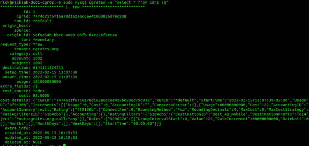
Well, if you’ve got CDR storage in StoreDB enabled (And you probably do if you’ve been following up until this point), then the answer is a MySQL table, and we can retrive the data with:
sudo mysql cgrates -e "select * from cdrs \G"
For those of you with a bit of MySQL experience under your belt, you’d be able to envisage using the SUM function to total a monthly bill for a customer from this.
Of course we can add CDRs via the API, and you probably already guessed this, but we can retrive CDRs via the API as well, filtering on the key criteria:
This would be useful for generating an invoice or populating recent calls for a customer portal.
Maybe creating rated CDRs and sticking them into a database is exactly what you’re looking to achieve in CGrateS – And if so, great, this is where you can stop – but for many use cases, there’s a want for an automated solution – For your platform to automatically integrate with CGrateS.
If you’ve got an Asterisk/FreeSWITCH/Kamailio or OpenSIPs based platform, then you can integrate CGrateS directly into your platform to add the CDRs automatically, as well as access features like prepaid credit control, concurrent call limits, etc, etc. The process is a little different on each of these platforms, but ultimately under the hood, all of these platforms have some middleware that generates the same API calls we just ran to create the CDR.
So far this tutorial has been heavy on teaching the API, because that’s what CGrateS ultimately is – An API service.
Our platforms like Asterisk and Kamailio with the CGrateS plugins are just CGrateS API clients, and so once we understand how to use and interact with the API it’s a breeze to plug in the module for your platform to generate the API calls to CGrateS required to integrate.
In our last post we introduced the CGrateS API and we used it to add Rates, Destinations and define DestinationRates.
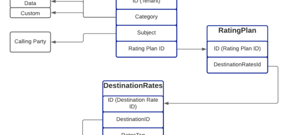
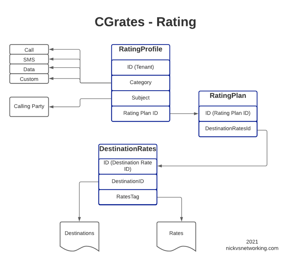
In this post, we’ll create the RatingPlan that references the DestinationRate we just defined, and the RatingProfile that references the RatingPlan, and then, as the cherry on top – We’ll rate some calls.
For anyone looking at the above diagram for the first time, you might be inclined to ask why what is the purpose of having all these layers?
This layered architecture allows all sorts of flexibility, that we wouldn’t otherwise have, for example, we can have multiple RatingPlans defined for the same Destinations, to allow us to have different Products defined, with different destinations and costs.
Likewise we can have multiple RatingProfiles assigned for the same destinations to allow us to generate multiple CDRs for each call, for example a CDR to bill the customer with and a CDR with our wholesale cost.
All this flexibility is enabled by the layered architecture.
Define RatingPlan
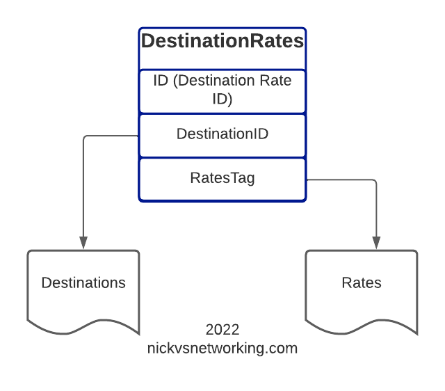
Picking up where we left off having just defined the DestinationRate, we’ll need to create a RatingPlan and link it to the DestinationRate, so let’s check on our DestinationRates:
From the output we can see we’ve got the DestinationRate defined, there’s a lot of info returned (I’ve left out most of it), but you can see the Destination, and the Rate associated with it is returned:
So after confirming that our DestinationRates are there, we’ll create a RatingPlan to reference it, for this we’ll use the APIerSv1.SetTPRatingPlan API call.
In our basic example, this really just glues the DestinationRate_AU object to RatingPlan_VoiceCalls.
It’s worth noting that you can use a RatingPlan to link to multiple DestinationRates, for example, we might want to have a different RatingPlan for each region / country, we can do that pretty easily too, in the below example I’ve referenced other Destination Rates (You’d go about defining the DestinationRates for these other destinations / rates the same way as we did in the last example).
One last step before we can test this all end-to-end, and that’s to link the RatingPlan we just defined with a RatingProfile.
StorDB & DataDB
Psych! Before we do that, I’m going to subject you to learning about backends for a while.
So far we’ve skirted around CGrateS architecture, but this is something we need to know for now.
To keep everything fast, a lot of data is cached in what is called a DataDB (if you’ve followed since part 1, then your DataDB is Redis, but there are other options).
To keep everything together, databases are used for storage, called StorDB (in our case we are using MySQL, but again, we can have other options) but calls to this database are minimal to keep the system fast.
If you’re an astute reader, you may have noticed many of our API calls have TP in method name, if the API call has TP in the name, it is storing it in the StoreDB, if it doesn’t, it means it’s storing it only in DataDB.
Why does this matter? Well, let’s look a little more closely and it will become clear:
ApierV1.SetRatingProfile will set the data only in DataDB (Redis), because it’s in the DataDB the change will take effect immediately.
ApierV1.SetTPRatingProfile will set the data only in StoreDB (MySQL), it will not take effect until it is copied from the database (StoreDB) to the cache (DataDB).
After we define the RatingPlan, we need to run this command prior to creating the RatingProfile, so it has something to reference, so we’ll do that by adding:
The last piece of the puzzle to define is the RatingProfile.
We define a few key things in the rating profile:
The Tenant – CGrateS is multitenant out of the box (in our case we’ve used tenant named “cgrates.org“, but you could have different tenants for different customers).
The Category – As we covered in the first post, CGrateS can bill voice calls, SMS, MMS & Data consumption, in this scenario we’re billing calls so we have the value set to *call, but we’ve got many other options. We can use Category to link what RatingPlan is used, for example we might want to offer a premium voice service with guaranteed CLI rates, using a different RatingPlan that charges more per call, or maybe we’re doing mobile and we want a different RatingPlan for use when Roaming, we can use Category to switch that.
The Subject – This is loosely the Source / Calling Party; in our case we’re using a wildcard value *any which will match any Subject
The RatingPlanActivations list the RatingPlanIds of the RatingPlans this RatingProfile uses
So let’s take a look at what we’d run to add this:
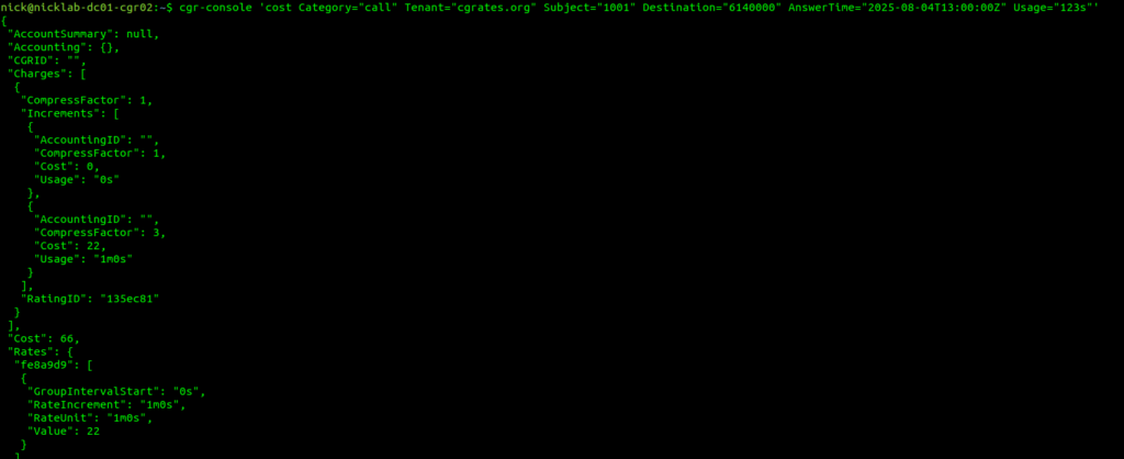
Okay, so at this point, all going well, we should have some data loaded, we’ve gone through all those steps to load this data, so now let’s simulate a call to a Mobile Number (22c per minute) for 123 seconds.
We cheated a fair bit, to show something that worked, but it’s not something you’d probably want to use in real life, loading static CSV files gets us off the ground, but in reality we don’t want to manage a system through CSV files.
Instead, we’d want to use an API.
Fair warning – There is some familiarity expected with JSON and RESTful APIs required, we’ll use Python3 for our examples, but you can use any programing language you’re comfortable with, or even CURL commands.
So we’re going to start by clearing out all the data we setup in CGrateS using the cgr-loader tool from those imported CSVs:
redis-cli flushall
sudo mysql -Nse 'show tables' cgrates | while read table; do sudo mysql -e "truncate table $table" cgrates; done
cgr-migrator -exec=*set_versions -stordb_passwd=CGRateS.org
sudo systemctl restart cgrates
So what have we just done? Well, we’ve just cleared all the data in CGrateS. We’re starting with a blank slate.
In this post, we’re going to define some Destinations, some Rates to charge and then some DestinationRates to link each Destination to a Rate.
But this time we’ll be doing this through the CGrateS API.
Introduction to the CGrateS API
CGrateS is all API driven – so let’s get acquainted with this API.
I’ve written a simple Python wrapper you can find here that will make talking to CGRateS a little easier, so let’s take it for a spin and get the Destinations that are loaded into our system:
import cgrateshttpapi
CGRateS_Obj = cgrateshttpapi.CGRateS('172.16.41.133', 2080) #Replace this IP with the IP Address of your CGrateS instance...

destinations = CGRateS_Obj.SendData({'method':'ApierV1.GetTPDestinationIDs','params':[{"TPid":"cgrates.org"}]})['result']

#Pretty print the result:
print("Destinations: ")
pprint.pprint(destinations)
All going well you’ll see something like this back:
Initializing with host 172.16.41.133 on port 2080
Sending Request with Body:
{'method': 'ApierV2.Ping', 'params': [{'Tenant': 'cgrates.org'}]}
Sending Request with Body:
{'method': 'ApierV2.GetTPDestinationIDs', 'params': [{"TPid":"cgrates.org"}]}
Destinations from CGRates: []
So what did we just do? Well, we sent a JSON formatted string to the CGRateS API at 172.16.41.133 on port 2080 – You’ll obviously need to change this to the IP of your CGrateS instance.
In the JSON body we sent we asked for all the Destinations using the ApierV1.GetTPDestinationIDs method, for the TPid ‘cgrates.org’,
And it looks like no destinations were sent back, so let’s change that!
Note: There’s API Version 1 and API Version 2, not all functions exist in both (at least not in the docs) so you have to use a mix.
Adding Destinations via the API
So now we’ve got our API setup, let’s see if we can add a destination!
To add a destination, we’ll need to go to the API guide and find the API call to add a destination – in our case the API call is ApierV2.SetTPDestination and will look like this:
So we’re creating a Destination named Dest_AU_Mobile and Prefix 614 will match this destination.
Note: I like to prefix all my Destinations with Dest_, all my rates with Rate_, etc, so it makes it easy when reading what’s going on what object is what, you may wish to do the same!
So we’ll use the Python code we had before to list the destinations, but this time, we’ll use the ApierV2.SetTPDestination API call to add a destination before listing them, let’s take a look:
If we post this to the CGR engine, we’ll create a rate, named Rate_AU_Mobile_Rate_1 that bills 22 cents per minute, charged every 60 seconds.
Let’s add a few rates:
CGRateS_Obj.SendData({"method":"ApierV1.SetTPRate","params":[{"ID":"Rate_AU_Mobile_Rate_1","TPid":"cgrates.org","RateSlots":[{"ConnectFee":0,"Rate":22,"RateUnit":"60s","RateIncrement":"60s","GroupIntervalStart":"0s"}]}],"id":1})
CGRateS_Obj.SendData({"method":"ApierV1.SetTPRate","params":[{"ID":"Rate_AU_Fixed_Rate_1","TPid":"cgrates.org","RateSlots":[{"ConnectFee":0,"Rate":14,"RateUnit":"60s","RateIncrement":"60s","GroupIntervalStart":"0s"}]}],"id":1})
CGRateS_Obj.SendData({"method":"ApierV1.SetTPRate","params":[{"ID":"Rate_AU_Toll_Free_Rate_1","TPid":"cgrates.org","RateSlots":[{"ConnectFee":25,"Rate":0,"RateUnit":"60s","RateIncrement":"60s","GroupIntervalStart":"0s"}]}],"id":1})

TPRateIds = CGRateS_Obj.SendData({"method":"ApierV1.GetTPRateIds","params":[{"TPid":"cgrates.org"}]})['result']
print(TPRateIds)
for TPRateId in TPRateIds:
    print("\tRate: " + str(TPRateId))
All going well, when you add the above, we’ll have added 3 new rates:
Rate Name
Cost
Rate_AU_Fixed_Rate_1
14c per minute charged every 60s
Rate_AU_Mobile_Rate_1
22c per minute charged every 60s
Rate_AU_Toll_Free_Rate_1
25c connection, untimed
Rates we just created
Linking Rates to Destinations
So now with Destinations defined, and Rates defined, it’s time to link these two together!
Destination Rates link our Destinations and Route rates, this decoupling means that we can have one Rate shared by multiple Destinations if we wanted, and makes things very flexible.
For this example, we’re going to map the Destinations to rates like this:
All going well, you’ll see the new DestinationRate we added.
Here’s a good chance to show how we can add multiple bits of data in one API call, we can tweak the ApierV1.SetTPDestinationRate method and include all the DestinationRates we need in one API call:
In our next post, we’ll keep working our way up this diagram, by creating RatingPlans and RatingProfiles to reference the DestinationRate we just created.
Unstructured Supplementary Service Data or “USSD” is the stack used in Cellular Networks to offer interactive text based menus and systems to Subscribers.
If you remember topping up your mobile phone credit via a text menu on your flip phone, there’s a good chance that was USSD*.
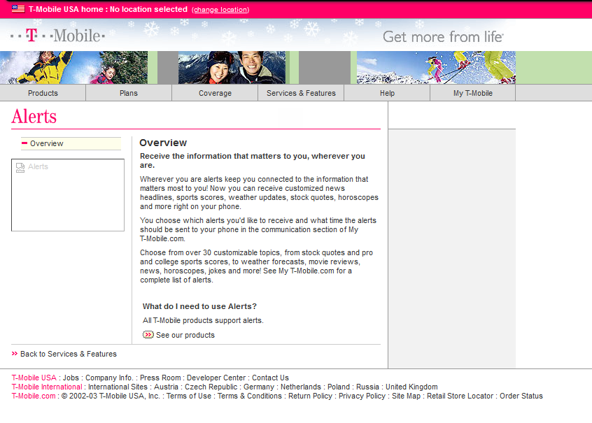
For a period, USSD Services provided Sporting Scores, Stock Prices and horoscopes on phones and networks that were not enabled for packet data.
Unlike plain SMS-PP, USSD services are transaction stateful, which means that there is a session / dialog between the subscriber and the USSD gateway that keeps track of the session and what has happened in the session thus far.
T-Mobile website from 2003 covering the features of their USSD based product at the time
Today USSD is primarily used in the network at times when a subscriber may not have balance to access packet data (Internet) services, so primarily is used for recharging with vouchers.
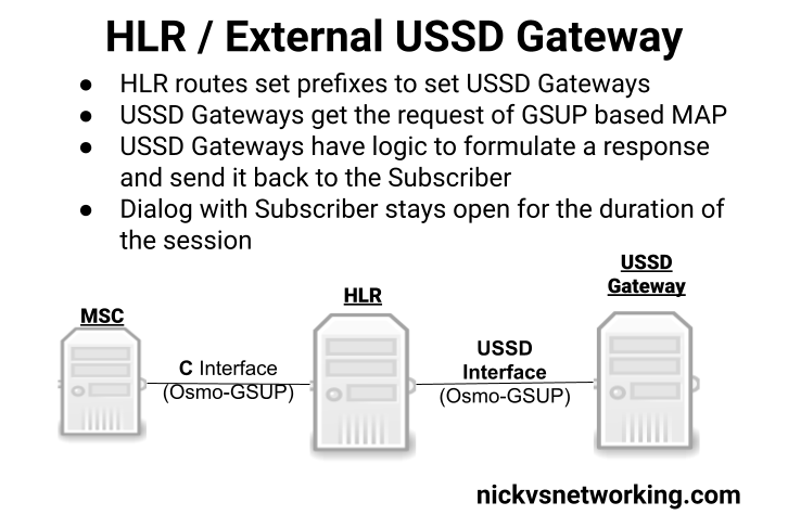
Osmocom’s HLR (osmo-hlr) has an External USSD interface to allow you to define the USSD logic in another entity, for example you could interface the USSD service with a chat bot, or interface with a billing system to manage credit.
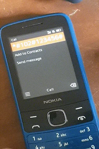
Using the example code provided I made a little demo of how the service could be used:
Communication between the USSD Gateway and the HLR is MAP but carried GSUP (Rather than the full MTP3/SCCP/TCAP layers that traditionally MAP stits on top of), and inside the HLR you define the prefixes and which USSD Gateway to route them to (This would allow you to have multiple USSD gateways and route the requests to them based on the code the subscriber sends).
(I had hoped to make a Python example and actually interface it with some external systems, but another day!)
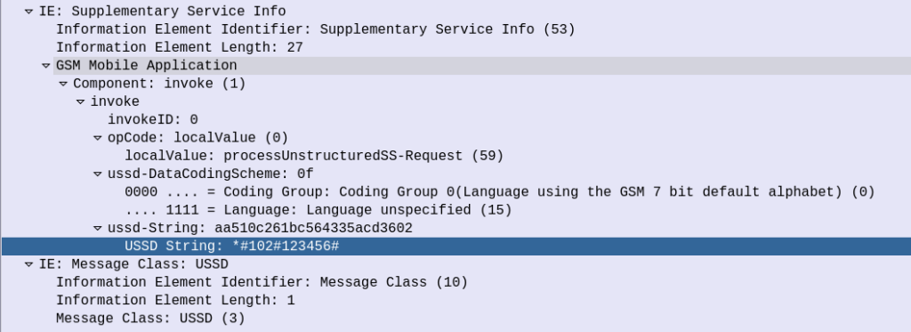
The signaling is fairly straight forward, when the subscriber kicks off the USSD request, the HLR calls a MAP Invoke operation for “processUnstructuredSS-Request”
Unfortunately is seems the stock Android does not support interactive USSD. This is exposed in the Android SDK so applications can access USSD interfaces (including interactive USSD) but the stock dialer on the few phones I played with did not, which threw a bit of a spanner in the works. There are a few apps that can help with this however I didn’t go into any of them.
(or maybe they used SIM Toolkit which had a similar interface)
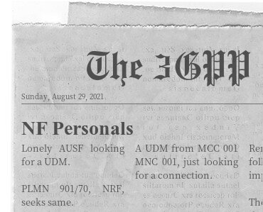
So I’ve been waxing lyrical about how cool in the NRF is, but what about how it’s secured?
A matchmaking service for service-consuming NFs to find service-producing NFs makes integration between them a doddle, but also opens up all sorts of attack vectors.
Theoretical Nasty Attacks (PoC or GTFO)
Sniffing Signaling Traffic: A malicious actor could register a fake UDR service with a higher priority with the NRF. This would mean UDR service consumers (Like the AUSF or UDM) would send everything to our fake UDR, which could then proxy all the requests to the real UDR which has a lower priority, all while sniffing all the traffic.
Stealing SIM Credentials: Brute forcing the SUPI/IMSI range on a UDR would allow the SIM Card Crypto values (K/OP/Private Keys) to be extracted.
Sniffing User Traffic: A dodgy SMF could select an attacker-controlled / run UPF to sniff all the user traffic that flows through it.
Obviously there’s a lot more scope for attack by putting nefarious data into the NRF, or querying it for data gathering, and I’ll see if I can put together some examples in the future, but you get the idea of the mischief that could be managed through the NRF.
This means it’s pretty important to secure it.
OAuth2
3GPP selected to use common industry standards for HTTP Auth, including OAuth2 (Clearly lessons were learned from COMP128 all those years ago), however OAuth2 is optional, and not integrated as you might expect. There’s a little bit to it, but you can expect to see a post on the topic in the next few weeks.
3GPP Security Recommendations
So how do we secure the NRF from bad actors?
Well, there’s 3 options according to 3GPP:
Option 1 – Mutual TLS
Where the Client (NF) and the Server (NRF) share the same TLS info to communicate.
This is a pretty standard mechanism to use for securing communications, but the reliance on issuing certificates and distributing them is often done poorly and there is no way to ensure the person with the certificate, is the person the certificate was issued to.
3GPP have not specified a mechanism for issuing and securely distributing certificates to NFs.
Option 2 – Network Domain Security (NDS)
Split the network traffic on a logical level (VLANs / VRFs, etc) so only NFs can access the NRF.
Essentially it’s logical network segregation.
Option 3 – Physical Security
Split the network like in NDS but a physical layer, so the physical cables essentially run point-to-point from NF to NRF.
NRF and NF shall authenticate each other during discovery, registration, and access token request. If the PLMN uses protection at the transport layer as described in clause 13.1, authentication provided by the transport layer protection solution shall be used for mutual authentication of the NRF and NF. If the PLMN does not use protection at the transport layer, mutual authentication of NRF and NF may be implicit by NDS/IP or physical security (see clause 13.1). When NRF receives message from unauthenticated NF, NRF shall support error handling, and may send back an error message. The same procedure shall be applied vice versa. After successful authentication between NRF and NF, the NRF shall decide whether the NF is authorized to perform discovery and registration. In the non-roaming scenario, the NRF authorizes the Nnrf_NFDiscovery_Request based on the profile of the expected NF/NF service and the type of the NF service consumer, as described in clause 4.17.4 of TS23.502 [8].In the roaming scenario, the NRF of the NF Service Provider shall authorize the Nnrf_NFDiscovery_Request based on the profile of the expected NF/NF Service, the type of the NF service consumer and the serving network ID. If the NRF finds NF service consumer is not allowed to discover the expected NF instances(s) as described in clause 4.17.4 of TS 23.502[8], NRF shall support error handling, and may send back an error message. NOTE 1: When a NF accesses any services (i.e. register, discover or request access token) provided by the NRF , the OAuth 2.0 access token for authorization between the NF and the NRF is not needed.
TS 133 501 – 13.3.1 Authentication and authorization between network functions and the NRF
The Network Repository Function plays matchmaker to all the elements in our 5G Core.
For our 5G Service-Based-Architecture (SBA) we use Service Based Interfaces (SBIs) to communicate between Network Functions. Sometimes a Network Function acts as a server for these interfaces (aka “Service Producer”) and sometimes it acts as a client on these interfaces (aka “Service Consumer”).
For service consumers to be able to find service producers (Clients to be able to find servers), we need a directory mechanism for clients to be able to find the servers to serve their needs, this is the role of the NRF.
With every Service Producer registering to the NRF, the NRF has knowledge of all the available Service Producers in the network, so when a Service Consumer NF comes along (Like an AMF looking for UDM), it just queries the NRF to get the details of who can serve it.
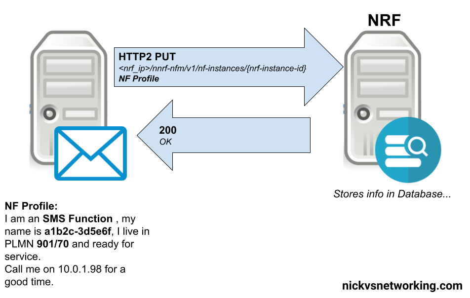
Basic Process – NRF Registration
In order to be found, a service producer NF has to register with the NRF, so the NRF has enough info on the service-producer to be able to recommend it to service-consumers.
This is all the basic info, the Service Based Interfaces (SBIs) that this NF serves, the PLMN, and the type of NF.
The NRF then stores this information in a database, ready to be found by SBI Service Consumers.
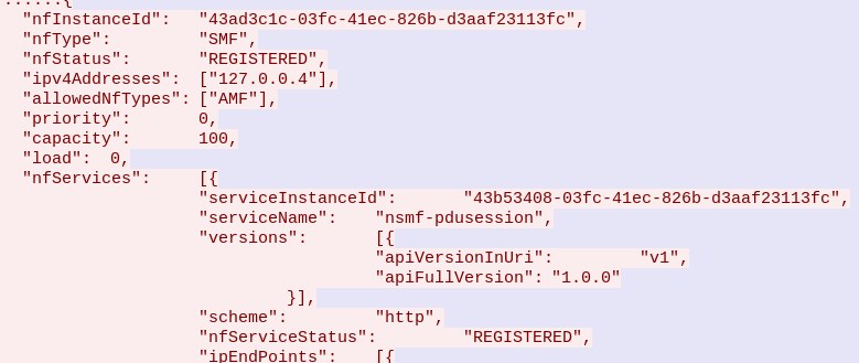
This is achieved by the Service Producing NF sending a HTTP2 PUT to the NRF, with the message body containing all the particulars about the services it offers.
Simplified example of an SMSc registering with the NRF in a 5G Core
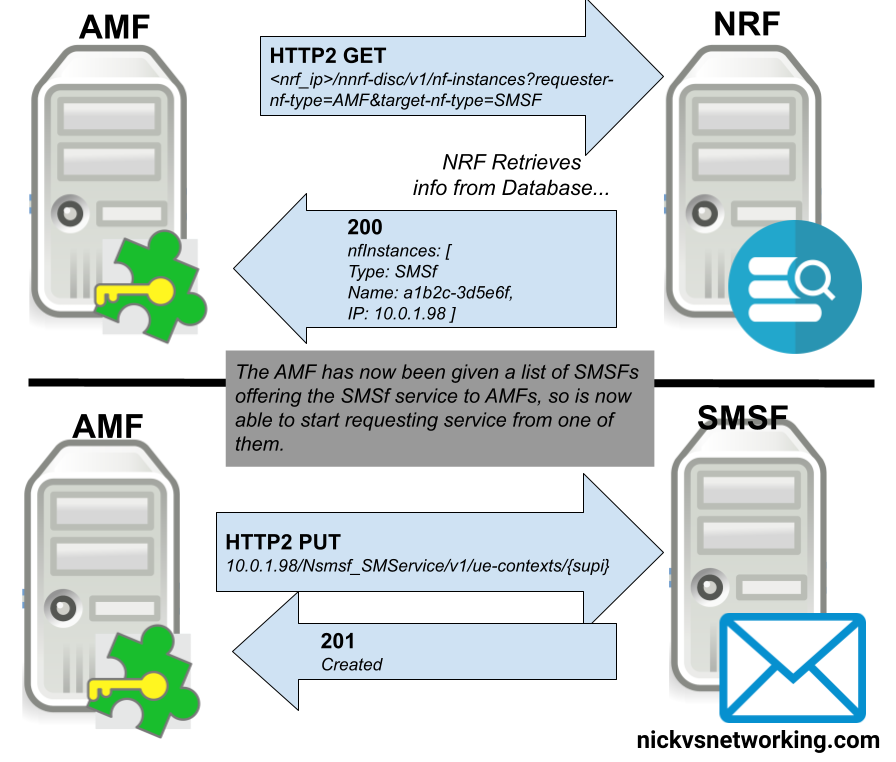
Basic Process – NRF Discovery
With an NRF that has a few SBI Service Producers registered in it, we can now start querying it from SBI Service Consumers, to find SBI Service Producers.
The SBI Service Consumer looking for a SBI Service Producer, queries the NRF with a little information about itself, and the SBI Service Producer it’s looking for.
For example a SMF looking for a UDM, sends a request like:
You may find you need to move your Open5GS deployments from one server to another, or split them between servers. This post covers the basics of migrating Open5GS config and data between servers by backing up and restoring it elsewhere.
The Database
Open5GS uses MongoDB as the database for the HSS and PCRF. This database contains all our SDM data, like our SIM Keys, Subscriber profiles, PCC Rules, etc.
Backup Database
To backup the MongoDB database run the below command (It doesn’t need sudo / root to run):
mongodump -o Open5Gs_"`date +"%d-%m-%Y"`"
You should get a directory called Open5Gs_todaysdate, the files in that directory are the output of the MongoDB database.
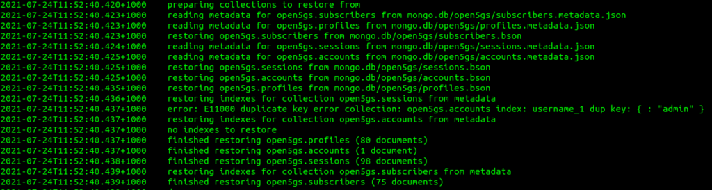
Restore Database
If you copy the backup we just took (the directory named Open5Gs_todaysdate) to the new server, you can restore the complete database by running:
mongorestore Open5Gs_todaysdate
This restores everything in the database, including profiles and user accounts for the WebUI,
You may instead just restore the Subscribers table, leaving the Profiles and Accounts unchanged with:
The database schema used by Open5GS changed earlier this year, meaning you cannot migrate directly from an old database to a new one without first making a few changes.
While reading through the 3GPP docs regarding Online Charging, there’s a concept that can be a tad confusing, and that’s the difference between Centralized and Non-Centralized Charging architectures.
The overall purpose of online charging is to answer that deceptively simple question of “does the user have enough credit for this action?”.
In order to answer that question, we need to perform rating and unit determination.
Rating
Rating is just converting connectivity credit units into monetary units.
If you go to the supermarket and they have boxes of Jaffa Cakes at $2.50 each, they have rated a box of Jaffa Cakes at $2.50.
1 Box of Jaffa Cakes rated at $2.50 per box
In a non-snack-cake context, such as 3GPP Online Charging, then we might be talking about data services, for example $1 per GB is a rate for data. Or for a voice calls a cost per minute to call a destination, such as is $0.20 per minute for a local call.
Rating is just working out the cost per connectivity unit (Data or Minutes) into a monetary cost, based on the tariff to be applied to that subscriber.
Unit Determination
The other key piece of information we need is the unit determination which is the calculation of the number of non-monetary units the OCS will offer prior to starting a service, or during a service.
This is done after rating so we can take the amount of credit available to the subscriber and calculate the number of non-monetary units to be offered.
Converting Hard-Currency into Soft-Snacks
In our rating example we rated a box of Jaffa Cakes at $2.50 per box. If I have $10 I can go to the shops and buy 4x boxes of Jaffa cakes at $2.50 per box. The cashier will perform unit determination and determine that at $2.50 per box and my $10, I can have 4 boxes of Jaffa cakes.
Again, steering away from the metaphor of the hungry author, Unit Determination in a 3GPP context could be determining how many minutes of talk time to be granted. Question: At $0.20 per minute to a destination, for a subscriber with a current credit of $20, how many minutes of talk time should they be granted? Answer: 100 minutes ($20 divided by $0.20 per minute is 100 minutes).
Or to put this in a data perspective, Question: Subscriber has $10 in Credit and data is rated at $1 per GB. How many GB of data should the subscriber be allowed to use? Answer: 10GB.
Putting this Together
So now we understand rating (working out the conversion of connectivity units into monetary units) and unit determination (determining the number of non-monetary units to be granted for a given resource), let’s look at the the Centralized and Decentralized Online Charging.
Centralized Rating
In Centralized Rating the CTF (Our P-GW or S-CSCF) only talk about non-monetary units. There’s no talk of money, just of the connectivity units used.
The CTFs don’t know the rating information, they have no idea how much 1GB of data costs to transfer in terms of $$$.
For the CTF in the P-GW/PCEF this means it talks to the OCS in terms of data units (data In/out), not money.
For the CTF in the S-CSCF this means it only ever talks to the OCS in voice units (minutes of talk time), not money.
This means our rates only need to exist in the OCS, not in the CTF in the other network elements. They just talk about units they need.
De-Centralized Rating
In De-Centralized Rating the CTF performs the unit conversion from money into connectivity units. This means the OCS and CTF talk about Money, with the CTF determining from that amount of money granted, what the subscriber can do with that money.
This means the CTF in the S-CSCF needs to have a rating table for all the destinations to determine the cost per minute for a call to a destination.
And the CTF in the P-GW/PCEF has to know the cost per octet transferred across the network for the subscriber.
In previous generations of mobile networks it may have been desirable to perform decentralized rating, as you can spread the load of calculating our the pricing, however today Centralized is the most common way to approach this, as ensuring the correct rates are in each network element is a headache.
Centralized Unit Determination
In Centralized Unit Determination the CTF tells the OCS the type of service in the Credit Control Request (Requested Service Units), and the OCS determines the number of non-monetary units of a certain service the subscriber can consume.
The CTF doesn’t request a value, just tells the OCS the service being requested and subscriber, and the OCS works out the values.
For example, the S-CSCF specifies in the Credit Control Request the destination the caller wishes to reach, and the OCS replies with the amount of talk time it will grant.
Or for a subscriber wishing to use data, the P-GW/PCEF sends a Credit Control Request specifying the service is data, and the OCS responds with how much data the subscriber is entitled to use.
De-Centralized Unit Determination
In De-Centralized Unit Determination, the CTF determines how many units are required to start the service, and requests these units from the OCS in the Credit Control Request.
For a data service,the CTF in the P-GW would determine how many data units it is requesting for a subscriber, and then request that many units from the OCS.
For a voice call a S-CSCF may request an initial call duration, of say 5 minutes, from the OCS. So it provides the information about the destination and the request for 300 seconds of talk time.
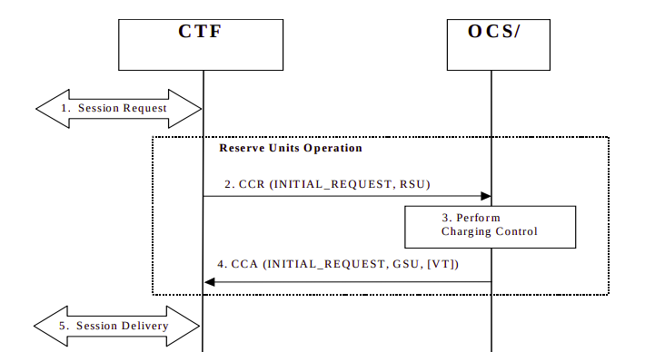
Session Charging with Unit Reservation (SCUR)
Arguably the most common online charging scenario is Session Charging with Unit Reservation (SCUR).
SCUR relies on reserving an amount of funds from the subscriber’s balance, so no other services can those funds and translating that into connectivity units (minutes of talk time or data in/out based on the Requested Session Unit) at the start of the session, and then subsequent requests to debit the reserved amount and reserve a new amount, until all the credit is used.
This uses centralized Unit Determination and centralized Rating.
Let’s take a look at how this would look for the CTF in a P-GW/PCEF performing online charging for a subscriber wishing to use data:
Session Request: The subscriber has attached to the network and is requesting service.
The CTF built into the P-GW/PCEF sends a Credit Control Request: Initial Request (As this subscriber has just attached) to the OCS, with Requested Service Units (RSU) of data in/out to the OCS.
The OCS performs rating and unit determination, and according to it’s credit risk policies, and a whole lot of other factors, comes back with an amount of data the subscriber can use, and reserves the amount from the account. (It’s worth noting at this point that this is not necessarily all of the subscriber’s credit in the form of data, just an amount the OCS is willing to allocate. More data can be requested once this allocated data is used up.)
The OCS sends a Credit Control Answer back to our P-GW/PCEF. This contains the Granted Service Unit (GSU), in our case the GSU is data so defines much data up/down the user can transfer. It also may include a Validity Time (VT), which is the number of seconds the Credit Control Answer is valid for, after it’s expired another Credit Control Request must be sent by the CTF.
Our P-GW/PCEF processes this, starts measuring the data used by the subscriber for reporting later, and sets a timer for the Validity Time to send another CCR at that point. At this stage, our subscriber is able to start using data.
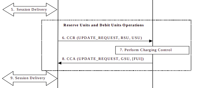
Some time later, either when all the data allocated in the Granted Service Units has been consumed, or when the Validity Time has expired, the CTF in the P-GW/PCEF sends another Credit Control Request:Update, and again includes the RSU (Requested Service Units) as data in/out, and also a USU (Used Service Units) specifying how much data the subscriber has used since the first Credit Control Answer.
The OCS receives this information. It compares the Used Session Units to the Granted Session Units from earlier, and with this is able to determine how much data the subscriber has actually used, and therefore how much credit that equates to, and debit that amount from the account. With this information the OCS can reserve more funds and allocate another GSU (Granted Session Unit) if the subscriber has the required balance. If the subscriber only has a small amount of credit left the FUI (Final Unit Indication AVP) is set to determine this is all the subscriber has left in credit, and if this is exhausted to end the session, rather than sending another Credit Control Request.
The Credit Control Answer with new GSU and the FUI is sent back to the P-GW/PCEF
The P-GW/PCEF allows the session to continue, again monitoring used traffic against the GSU (Granted Session Units).
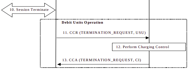
Once the subscriber has used all the data in the Granted Session Units, and as the last CCA included the Final Unit Indicator, the CTF in the P-GW/PCEF knows it can’t just request more credit in the form of a CCR Update, so cuts of the subscribers’s session.
The P-GW/PCEF then sends a Credit Control Request: Termination Request with the final Used Service Units to the OCS.
The OCS debits the used service units from the subscriber’s balance, and refunds any unused credit reservation.
The OCS sends back a Credit Control Answer which may include the CI value for Credit Information, to denote the cost information which may be passed to the subscriber if required.
Today, we’re going to look at one of the simplest Service Based Interfaces in the 5G Core, the Equipment Identity Register (EIR).
The purpose of the EIR is very simple – When a subscriber connects to the network it’s Permanent Equipment Identifier (PEI) can be queried against an EIR to determine if that device should be allowed onto the network or not.
The PEI is the IMEI of a phone / device, with the idea being that stolen phones IMEIs are added to a forbidden list on the EIR, and prohibited from connecting to the network, making them useless, in turn making stolen phones harder to resell, deterring mobile phone theft.
In reality these forbidden-lists are typically either country specific or carrier specific, meaning if the phone is used in a different country, or in some cases a different carrier, the phone’s IMEI is not in the forbidden-list of the overseas operator and can be freely used.
The dialog goes something like this:
AMF: Hey EIR, can PEI 49-015420-323751-8 connect to the network?
EIR: (checks if 49-015420-323751-8 in forbidden list - It's not) Yes.
or
AMF: Hey EIR, can PEI 58-241992-991142-3 connect to the network?
EIR: (checks if 58-241992-991142-3 is in forbidden list - It is) No.
(Optionally the SUPI can be included in the query as well, to lock an IMSI to an IMEI, which is a requirement in some jurisdictions)
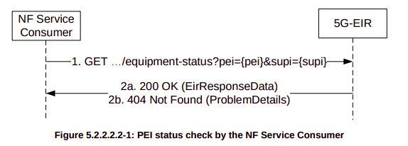
As we saw in the above script, the AMF queries the EIR using the N5g-eir_EquipmentIdentityCheck service.
The N5g-eir_EquipmentIdentityCheck service only offers one operation – CheckEquipmentIdentity.
It’s called by sending an HTTP GET to:
http://{apiRoot}/n5g-eir-eic/v1/equipment-status
Obviously we’ll need to include the PEI (IMEI) in the HTTP GET, which means if you remember back to basic HTTP GET, you may remember means you have to add ?attribute=value&attribute=value… for each attribute / value you want to share.
For the CheckEquipmentIdentity operation, the PEI is a mandatory parameter, and optionally the SUPI can be included, this means to query our PEI (The IMSI of the phone) against our EIR we’d simply send an HTTP GET to:
AMF: HTTP GET http://{apiRoot}/n5g-eir-eic/v1/equipment-status?pei=490154203237518
EIR: 200 (Body EirResponseData: status "WHITELISTED")
And how it would look for a blacklisted IMEI:
AMF: HTTP GET http://{apiRoot}/n5g-eir-eic/v1/equipment-status?pei=490154203237518
EIR: 404 (Body EirResponseData: status "BLACKLISTED")
Because it’s so simple, the N5g-eir_EquipmentIdentityCheck service is a great starting point for learning about 5G’s Service Based Interfaces.
Early on as subscriber trunk dialing and automated time-based charging was introduced to phone networks, engineers were faced with a problem from Payphones.
Previously a call had been a fixed price, once the caller put in their coins, if they put in enough coins, they could dial and stay on the line as long as they wanted.
But as the length of calls began to be metered, it means if I put $3 of coins into the payphone, and make a call to a destination that costs $1 per minute, then I should only be allowed to have a 3 minute long phone call, and the call should be cutoff before the 4th minute, as I would have used all my available credit.
Conversely if I put $3 into the Payphone and only call a $1 per minute destination for 2 minutes, I should get $1 refunded at the end of my call.
We see the exact same problem with prepaid subscribers on IMS Networks, and it’s solved in much the same way.
In LTE/EPC Networks, Diameter is used for all our credit control, with all online charging based on the Ro interface. So let’s take a look at how this works and what goes on.
Generic 3GPP Online Charging Architecture
3GPP defines a generic 3GPP Online charging architecture, that’s used by IMS for Credit Control of prepaid subscribers, but also for prepaid metering of data usage, other volume based flows, as well as event-based charging like SMS and MMS.
Network functions that handle chargeable services (like the data transferred through a P-GW or calls through a S-CSCF) contain a Charging Trigger Function (CTF) (While reading the specifications, you may be left thinking that the Charging Trigger Function is a separate entity, but more often than not, the CTF is built into the network element as an interface).
The CTF is a Diameter application that generates requests to the Online Charging Function (OCF) to be granted resources for the session / call / data flow, the subscriber wants to use, prior to granting them the service.
So network elements that need to charge for services in realtime contain a Charging Trigger Function (CTF) which in turn talks to an Online Charging Function (OCF) which typically is part of an Online Charging System (AKA OCS).
For example when a subscriber turns on their phone and a GTP session is setup on the P-GW/PCEF, but before data is allowed to flow through it, a Diameter “Credit Control Request” is generated by the Charging Trigger Function (CTF) in the P-GW/PCEF, which is sent to our Online Charging Server (OCS).
The “Credit Control Answer” back from the OCS indicates the subscriber has the balance needed to use data services, and specifies how much data up and down the subscriber has been granted to use.
The P-GW/PCEF grants service to the subscriber for the specified amount of units, and the subscriber can start using data.
This is a simplified example – Decentralized vs Centralized Rating and Unit Determination enter into this, session reservation, etc.
The interface between our Charging Trigger Functions (CTF) and the Online Charging Functions (OCF), is the Ro interface, which is a Diameter based interface, and is common not just for online charging for data usage, IMS Credit Control, MMS, value added services, etc.
3GPP define a reference online-charging interface, the Ro interface, and all the application-specific interfaces, like the Gy for billing data usage, build on top of the Ro interface spec.
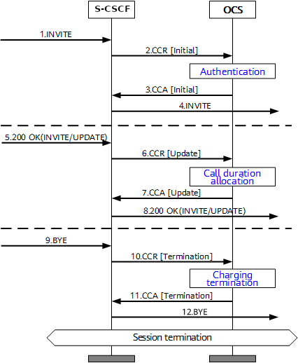
Basic Credit Control Request / Credit Control Answer Process
This example will look at a VoLTE call over IMS.
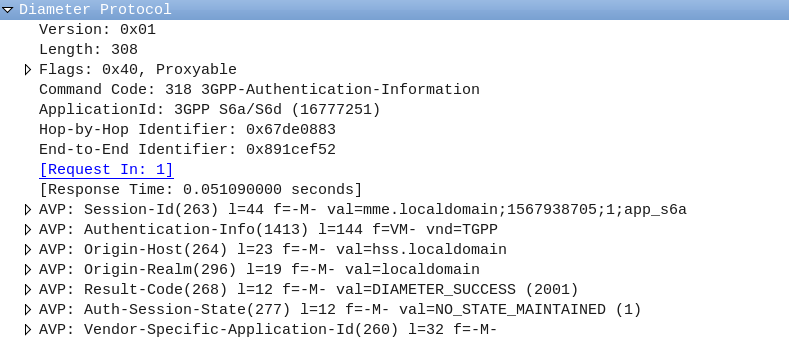
When a subscriber sends an INVITE, the Charging Trigger Function baked in our S-CSCF sends a Diameter “Credit Control Request” (CCR) to our Online Charging Function, with the type INITIAL, meaning this is the first CCR for this session.
The CCR contains the Service Information AVP. It’s this little AVP that is where the majority of the magic happens, as it defines what the service the subscriber is requesting. The main difference between the multitude of online charging interfaces in EPC networks, is just what the service the customer is requesting, and the specifics of that service.
For this example it’s a voice call, so this Service Information AVP contains a “IMS-Information” AVP. This AVP defines all the parameters for a IMS phone call to be online charged, for a voice call, this is the called-party, calling party, SDP (for differentiating between voice / video, etc.).
It’s the contents of this Service Information AVP the OCS uses to make decision on if service should be granted or not, and how many service units to be granted. (If Centralized Rating and Unit Determination is used, we’ll cover that in another post) The actual logic, relating to this decision is typically based on the the rating and tariffing, credit control profiles, etc, and is outside the scope of the interface, but in short, the OCS will make a yes/no decision about if the subscriber should be granted access to the particular service, and if yes, then how many minutes / Bytes / Events should be granted.
In the received Credit Control Answer is received back from our OCS, and the Granted-Service-Unit AVP is analysed by the S-CSCF. For a voice call, the service units will be time. This tells the S-CSCF how long the call can go on before the S-CSCF will need to send another Credit Control Request, for the purposes of this example we’ll imagine the returned value is 600 seconds / 10 minutes.
The S-CSCF will then grant service, the subscriber can start their voice call, and start the countdown of the time granted by the OCS.
As our chatty subscriber stays on their call, the S-CSCF approaches the limit of the Granted Service units from the OCS (Say 500 seconds used of the 600 seconds granted). Before this limit is reached the S-CSCF’s CTF function sends another Credit Control Request with the type UPDATE_REQUEST. This allows the OCS to analyse the remaining balance of the subscriber and policies to tell the S-CSCF how long the call can continue to proceed for in the form of granted service units returned in the Credit Control Answer, which for our example can be 300 seconds.
Eventually, and before the second lot of granted units runs out, our subscriber ends the call, for a total talk time of 700 seconds.
But wait, the subscriber been granted 600 seconds for our INITIAL request, and a further 300 seconds in our UPDATE_REQUEST, for a total of 900 seconds, but the subscriber only used 700 seconds?
The S-CSCF sends a final Credit Control Request, this time with type TERMINATION_REQUEST and lets the OCS know via the Used-Service-Unit AVP, how many units the subscriber actually used (700 seconds), meaning the OCS will refund the balance for the gap of 200 seconds the subscriber didn’t use.
If this were the interface for online charging of data, we’d have the PS-Information AVP, or for online charging of SMS we’d have the SMS-Information, and so on.
The architecture and framework for how the charging works doesn’t change between a voice call, data traffic or messaging, just the particulars for the type of service we need to bill, as defined in the Service Information AVP, and the OCS making a decision on that based on if the subscriber should be granted service, and if yes, how many units of whatever type.
While we’ve covered the Update Location Request / Response, where an MME is able to request subscriber data from the HSS, what about updating a subscriber’s profile when they’re already attached? If we’re just relying on the Update Location Request / Response dialog, the update to the subscriber’s profile would only happen when they re-attach.
We need a mechanism where the HSS can send the Request and the MME can send the response.
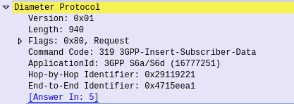
This is what the Insert Subscriber Data Request/Response is used for.
Let's imagine we want to allow a subscriber to access an additional APN, or change an AMBR values of an existing APN;

We'd send an Insert Subscriber Data Request from the HSS, to the MME, with the Subscription Data AVP populated with the additional APN the subscriber can now access.
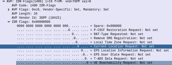
Beyond just updating the Subscription Data, the Insert Subscriber Data Request/Response has a few other funky uses.
Through it the HSS can request the EPS Location information of a Subscriber, down to the TAC / eNB ID serving that subscriber. It’s not the same thing as the GMLC interfaces used for locating subscribers, but will wake Idle UEs to get their current serving eNB, if the Current Location Request is set in the IDR Flags.
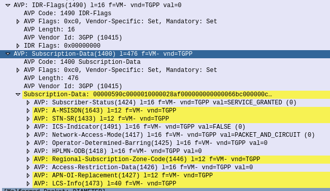
But the most common use for the Insert-Subscriber-Data request is to modify the Subscription Profile, contained in the Subscription-Data AVP,
If the All-APN-Configurations-Included-Indicator is set in the AVP info, then all the existing AVPs will be replaced, if it’s not then everything specified is just updated.
The Insert Subscriber Data Request/Response is a bit novel compared to other S6a requests, in this case it’s initiated by the HSS to the MME (Like the Cancel Location Request), and used to update an existing value.
Imagine a not-too distant future, one without flying cars – just one where 2G and 3G networks have been switched off.
And the imagine a teenage phone user, who has almost run out of their prepaid mobile data allocation, and so has switched mobile data off, or a roaming scenario where the user doesn’t want to get stung by an unexpectedly large bill.
In 2G/3G networks the Circuit Switched (Voice & SMS) traffic was separate to the Packet Switched (Mobile Data).
This allowed users to turn of mobile data (GPRS/HSDPA), etc, but still be able to receive phone calls and send SMS, etc.
With LTE, everything is packet switched, so turning off Mobile Data would cut off VoLTE connectivity, meaning users wouldn’t be able to make/recieve calls or SMS.
In 3GPP Release 14 (2017) 3GPP introduced the PS Data Off feature.
This feature is primarily implemented on the UE side, and simply blocks uplink user traffic from the UE, while leaving other background IP services, such as IMS/VoLTE and MMS, to continue working, even if mobile data is switched off.
The UE can signal to the core it is turning off PS Data, but it’s not required to, so as such from a core perspective you may not know if your subscriber has PS Data off or not – The default APN is still active and in the implementations I’ve tried, it still responds to ICMP Pings.
IMS Registration stays in place, SMS and MMS still work, just the UE just drops the requests from the applications on the device (In this case I’m testing with an Android device).
What’s interesting about this is that a user may still find themselves consuming data, even if data services are turned off. A good example of this would be push notifications, which are sent to the phone (Downlink data). The push notification will make it to the UE (or at least the TCP SYN), after all downlink services are not blocked, however the response (for example the SYN-ACK for TCP) will not be sent. Most TCP stacks when ignored, try again, so you’ll find that even if you have PS Data off, you may still use some of your downlink data allowance, although not much.
The SIM EF 3GPPPSDATAOFF defines the services allowed to continue flowing when PS Data is off, and the 3GPPPSDATAOFFservicelist EF lists which IMS services are allowed when PS Data is off.
Usually at this point, I’d include a packet capture and break down the flow of how this all looks in signaling, but when I run this in my lab, I can’t differentiate between a PS Data Off on the UE and just a regular bearer idle timeout… So have an irritating blinking screenshot instead…
DNS is commonly used for resolving domain names to IP Addresses, and is often described as being like “the phone book of the Internet”.
So what’s the phone book of phone books?
The answer, is (kind of) DNS. With the aid of E.164 number to URI mapping (ENUM), DNS can be used to resolve phone numbers into SIP URIs to route the traffic to.
So what is ENUM?
ENUM allows us to bypass the need for a central switch for routing calls to numbers, and instead, through a DNS lookup, resolve a phone number into a reachable SIP URI that is the ultimate destination for the traffic.
Imagine you want to call a company, you dial the phone number for that company, your phone does a DNS query against the phone number, which returns the SIP URI of the company’s PBX, and your phone sends the SIP INVITE directly to the company’s PBX, with no intermediary party carrying the call.
3GPP have specified ENUM as the prefered mechanism for resolving phone numbers into SIP addresses, and while it’s widespread adoption on the public Internet is still in its early days (See my post on The Sad story of ENUM in Australia) it is increasingly common in IMS networks and inside operator networks.
ENUM allow us to lookup a phone number on a DNS server and find the SIP URI a server that will handle traffic for the phone number, but it’s a bit more complicated than the A or AAAA records you’d use to resolve a website, ENUM relies on NAPTR records.
Let’s look at the steps involved in taking an E.164 number and knowing where to send it.
Step 1 – Reverse the Numbers
We read phone numbers from left to right.
This is because historically the switch needs to get all the long-distance routing sorted first. The switch has to route your call to the exchange that serves that subscriber, which is what all the area codes and prefixes assigned to areas are all about (Throwback to SZU for any old Telco buffs).
For an E.164 number you’ve got a Country Code, Area Code and then the Subscriber Number. The number gets more specific as it goes along.
But getting more specific as you go along is the opposite how how DNS works, millions of domains share the .com suffix, and the unique / specific part is the bits before that.
So the first step in the ENUM process is to reverse the phone number, so let’s take phone number (03) 5550 0912, which in E.164 is +61 3 5550 0912.
As the spaces in the phone numbers are there for the humans, we’ll drop all of them and reverse the number, as DNS is more specific right-to-left, so we end up with
2.1.9.0.0.5.5.5.3.1.6
Step 2 – Add the Suffix
The ITU ENUM specifies the suffix e164.arpa be assigned for public ENUM entries. Private ENUM deployments may use their own suffix, but to make life simple I’m going to use e164.arpa as if it were public.
So we’ll append the e164.arpa domain onto our reversed and formatted E.164 phone number:
2.1.9.0.0.5.5.5.3.1.6.e164.arpa
Step 3 – Query it
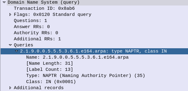
Next we’ll run a Naming Authority Pointer (NAPTR) query against the domain, to get back a list of records for that number.
DNS is a big topic, and NAPTR and SRV takes up a good chunk of it, but what you need to know is that by using NAPTR we’re not limited to just a single response, we could have a weighted pool of servers handling traffic for this phone number, and be able to control load through the use of NAPTR, amongst other things.
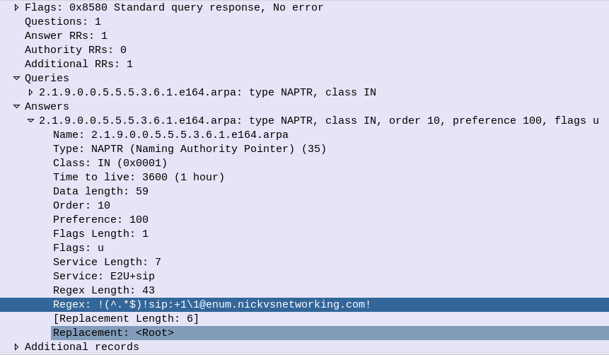
DNS NAPTR QueryDNS NAPTR Response
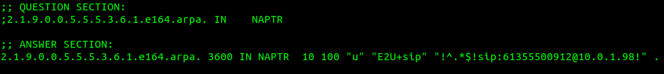
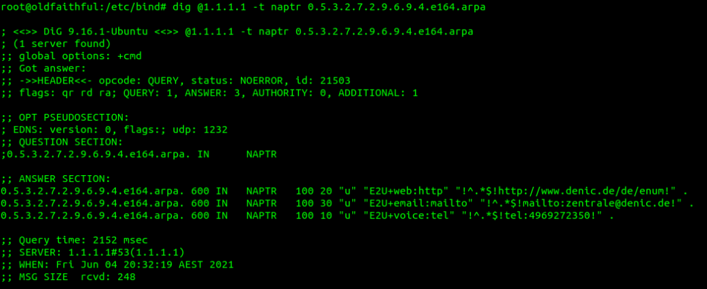
Of course, if our phone can query the public NAPTR records, then so can anyone else, so we can just use a tool like Dig to query the record ourselves,
In the answers section I’ve setup this DNS server to only return a single response, with the regex SIP URI to use, in my case that’s sip:[email protected]
You’ll obviously need to replace the DNS server with your DNS server, and the query with the reversed and formatted version of the E.164 number you wish to query.
Step 4 – Send SIP traffic
After looking at the NAPTR records returned and using the weight and priority to determine which server/s to send to first, our phone forwards an INVITE to the URI returned in the NAPTR record.
How to interpret the returned results?
The first thing to keep in mind when working with ENUM is multiple records being returned is supported, and even encouraged.
NAPTR results return 7 fields, which define how it should be handled.
The host part is fairly obvious, and defines the host / DNS entry we’re talking about.
The Service defines what type of service this is. ENUM can be expanded beyond just voice, for example you may want to also return an email address or IM address as well as a SIP Address on an ENUM query, which you can do. By default voice uses the “E2U+sip” service to identify SIP URIs to route calls to, so in this context that’s what we’re interested in, but keep in mind there are other types out there,
Example ENUM query against a phone number showing other types of services (Email & Web)
The Order simply defines the order in which the rules are to be parsed. Lower numbers are processed first, if no matches then the next lowest, and so on until the highest number is reached.
The Pref is the processing preference. For load balancing 50/50 between two sites say a Melbourne and Sydney site, we’d return two results, with the same Order, and the same Pref, would see traffic split 50/50 between the two sites. We could split this further, a Pref value of 10 for Melbourne, 10 for Sydney, 5 for Brisbane and 5 for Perth would see 33% of calls route to Melbourne, 33% of calls route to Sydney, 16.5% of calls route to Brisbane and 16.5% of calls route to Perth. This is because we’d have a total preference value of 30, and the individual preference for each entry would work out as the fraction of the total (ie Pref 10 out of 30 = 10/30 or 33.3%).
The Flags denote the type of record we’re going to get, for most ENUM traffic this is going to be set to U, to denote a SIP URI with Regex.
The regexp field contains our SIP URI in the form of a Regular expression, which can include pattern matching and replacement. This is most commonly used to fill in the phone number into the SIP URI, for example instead of hardcoding the phone number into the response, we could use a Regular expression to fill in the requested number into the SIP URI.
If you’re looking to implement ENUM for an internal network, great, I’ll have some more posts here over the next few weeks covering off configuration of a DNS server to support ENUM lookups, and using Kamailio to lookup ENUM routes.
In terms of public ENUM, while many carriers are using ENUM inside their networks, public adoption of ENUM in most markets has been slow, for a number of reasons.
Many incumbent operators have been reluctant to embrace public ENUM as their role as an operator would be relegated to that of a Domain registrar. Additionally, there’s real security risks involved in moving to ENUM – opening your phone system up to the world to accept inbound calls from anywhere. This could lead to DOS-style attacks of flooding phone numbers with automatically generated traffic, privacy risks and even less validation in terms of caller ID trust.
RIPE maintains the EnumData.org website listing the status of ENUM for each country / region.
Chances are if you’re reading this, you’re trying to work out what Telephony Binary-Coded Decimal encoding is. I got you.
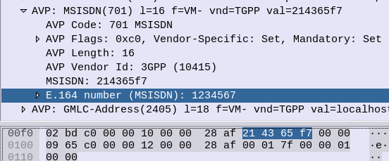
Again I found myself staring at encoding trying to guess how it worked, reading references that looped into other references, in this case I was encoding MSISDN AVPs in Diameter.
How to Encode a number using Telephony Binary-Coded Decimal encoding?
First, Group all the numbers into pairs, and reverse each pair.
So a phone number of 123456, becomes:
214365
Because 1 & 2 are swapped to become 21, 3 & 4 are swapped to become 34, 5 & 6 become 65, that’s how we get that result.
TBCD Encoding of numbers with an Odd Length?
If we’ve got an odd-number of digits, we add an F on the end and still flip the digits,
For example 789, we add the F to the end to pad it to an even length, and then flip each pair of digits, so it becomes:
87F9
That’s the abbreviated version of it. If you’re only encoding numbers that’s all you’ll need to know.
Detail Overload
Because the numbers 0-9 can be encoded using only 4 bits, the need for a whole 8 bit byte to store this information is considered excessive.
For example 1 represented as a binary 8-bit byte would be 00000001, while 9 would be 00001001, so even with our largest number, the first 4 bits would always going to be 0000 – we’d only use half the available space.
So TBCD encoding stores two numbers in each Byte (1 number in the first 4 bits, one number in the second 4 bits).
To go back to our previous example, 1 represented as a binary 4-bit word would be 0001, while 9 would be 1001. These are then swapped and concatenated, so the number 19 becomes 1001 0001 which is hex 0x91.
Let’s do another example, 82, so 8 represented as a 4-bit word is 1000 and 2 as a 4-bit word is 0010. We then swap the order and concatenate to get 00101000 which is hex 0x28 from our inputted 82.
Final example will be a 3 digit number, 123. As we saw earlier we’ll add an F to the end for padding, and then encode as we would any other number,
F is encoded as 1111.
1 becomes 0001, 2 becomes 0010, 3 becomes 0011 and F becomes 1111. Reverse each pair and concatenate 00100001 11110011 or hex 0x21 0xF3.
Special Symbols (#, * and friends)
Because TBCD Encoding was designed for use in Telephony networks, the # and * symbols are also present, as they are on a telephone keypad.
Astute readers may have noticed that so far we’ve covered 0-9 and F, which still doesn’t use all the available space in the 4 bit area.
The extended DTMF keys of A, B & C are also valid in TBCD (The D key was sacrificed to get the F in).
Symbol
4 Bit Word
*
1 0 1 0
#
1 0 1 1
a
1 1 0 0
b
1 1 0 1
c
1 1 1 0
So let’s run through some more examples,
*21 is an odd length, so we’ll slap an F on the end (*21F), and then encoded each pair of values into bytes, so * becomes 1010, 2 becomes 0010. Swap them and concatenate for our first byte of 00101010 (Hex 0x2A). F our second byte 1F, 1 becomes 0001 and F becomes 1111. Swap and concatenate to get 11110001 (Hex 0xF1). So *21 becomes 0x2A 0xF1.
And as promised, some Python code from PyHSS that does it for you:
    def TBCD_special_chars(self, input):
        if input == "*":
            return "1010"
        elif input == "#":
            return "1011"
        elif input == "a":
            return "1100"
        elif input == "b":
            return "1101"
        elif input == "c":
            return "1100"
        else:
            print("input " + str(input) + " is not a special char, converting to bin ")
            return ("{:04b}".format(int(input)))


    def TBCD_encode(self, input):
        print("TBCD_encode input value is " + str(input))
        offset = 0
        output = ''
        matches = ['*', '#', 'a', 'b', 'c']
        while offset < len(input):
            if len(input[offset:offset+2]) == 2:
                bit = input[offset:offset+2]    #Get two digits at a time
                bit = bit[::-1]                 #Reverse them
                #Check if *, #, a, b or c
                if any(x in bit for x in matches):
                    new_bit = ''
                    new_bit = new_bit + str(TBCD_special_chars(bit[0]))
                    new_bit = new_bit + str(TBCD_special_chars(bit[1]))
                    bit = str(int(new_bit, 2))
                output = output + bit
                offset = offset + 2
            else:
                bit = "f" + str(input[offset:offset+2])
                output = output + bit
                print("TBCD_encode output value is " + str(output))
                return output


    def TBCD_decode(self, input):
        print("TBCD_decode Input value is " + str(input))
        offset = 0
        output = ''
        while offset < len(input):
            if "f" not in input[offset:offset+2]:
                bit = input[offset:offset+2]    #Get two digits at a time
                bit = bit[::-1]                 #Reverse them
                output = output + bit
                offset = offset + 2
            else:   #If f in bit strip it
                bit = input[offset:offset+2]
                output = output + bit[1]
                print("TBCD_decode output value is " + str(output))
                return output
So it’s the not to distant future and the pundits vision of private LTE and 5G Networks was proved correct, and private networks are plentiful.
But what PLMN do they use?
The PLMN (Public Land Mobile Network) ID is made up of a Mobile Country Code + Mobile Network Code. MCCs are 3 digits and MNCs are 2-3 digits. It’s how your phone knows to connect to a tower belonging to your carrier, and not one of their competitors.
For example in Australia (Mobile Country Code 505) the three operators each have their own MCC. Telstra as the first licenced Mobile Network were assigned 505/01, Optus got 505/02 and VHA / TPG got 505/03.
Each carrier was assigned a PLMN when they started operating their network. But the problem is, there’s not much space in this range.
The PLMN can be thought of as the SSID in WiFi terms, but with a restriction as to the size of the pool available for PLMNs, we’re facing an IPv4 exhaustion problem from the start if we’re facing an explosion of growth in the space.
Let’s look at some ways this could be approached.
Everyone gets a PLMN
If every private network were to be assigned a PLMN, we’d very quickly run out of space in the range. Best case you’ve got 3 digits, so only space for 1,000 networks.
In certain countries this might work, but in other areas these PLMNs may get gobbled up fast, and when they do, there’s no more. New operators will be locked out of the market.
If you’re buying a private network from an existing carrier, they may permit you to use their PLMN,
Or if you’re buying kit from an existing vendor you may be able to use their PLMN too.
But what happens then if you want to move to a different kit vendor or another service provider? Do you have to rebuild your towers, reconfigure your SIMs?
Are you contractually allowed to continue using the PLMN of a third party like a hardware vendor, even if you’re no longer purchasing hardware from them? What happens if they change their mind and no longer want others to use their PLMN?
Everyone uses 999 / 99
The ITU have tried to preempt this problem by reallocating 999/99 for use in Private Networks.
The problem here is if you’ve got multiple private networks in close proximity, especially if you’re using CBRS or in close proximity to other networks, you may find your devices attempting to attach to another network with the same PLMN but that isn’t part of your network,
Mobile Country or Geographical Area Codes Note from TSB Following the agreement on the Appendix to Recommendation ITU-T E.212 on “shared E.212 MCC 999 for internal use within a private network” at the closing plenary of ITU-T SG2 meeting of 4 to 13 July 2018, upon the advice of ITU-T Study Group 2, the Director of TSB has assigned the Mobile Country Code (MCC) “999” for internal use within a private network.
Mobile Network Codes (MNCs) under this MCC are not subject to assignment and therefore may not be globally unique. No interaction with ITU is required for using a MNC value under this MCC for internal use within a private network. Any MNC value under this MCC used in a network has significance only within that network.
The MNCs under this MCC are not routable between networks. The MNCs under this MCC shall not be used for roaming. For purposes of testing and examples using this MCC, it is encouraged to use MNC value 99 or 999. MNCs under this MCC cannot be used outside of the network for which they apply. MNCs under this MCC may be 2- or 3-digit.
My bet is we’ll see the ITU allocate an MCC – or a range of MCCs – for private networks, allowing for a pool of PLMNs to use.
When deploying networks, Private network operators can try and pick something that’s not in use at the area from a pool of a few thousand options.
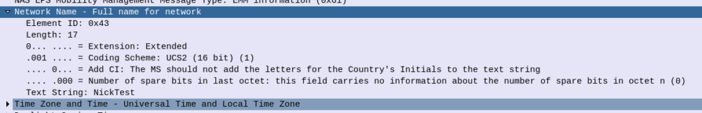
The major problem here is that there still won’t be an easy way to identify the operator of a particular network; the SPN is local only to the SIM and the Network Name is only present in the NAS messaging on an attach, and only after authentication.
If you’ve got a problem network, there’s no easy way to identify who’s operating it.
But as eSIMs become more prevalent and BIP / RFM on SIMs will hopefully allow operators to shift PLMNs without too much headache.
This is the simplest of the Diameter agents, but also probably the most common. The Diameter Relay agent does not look at the contents of the AVPs, it just routes messages based on the Application ID or Destination realm.
A Diameter Relay Agent does not change any AVPs except routing AVPs.
DRAs are transaction aware, but not dialog aware. This means they know if the Diameter request made it to the destination, but have no tracking of getting a response.
DRAs are common as a central hub for all Diameter hub in a network. This allows for a star topology where every Diameter service connects to a central DRA (typically two DRAs for redundancy) for a central place to manage Diameter routing, instead of having to do a full-mesh topology, which would be a nightmare on larger networks.
A Diameter Edge Agent is a special DRA that sits on the border between two networks and acts as a gateway between them.
Imagine a roaming exchange scenario, where each operator has to expose their core Diameter servers or DRAs to all the other operators they have roaming agreements with. Like we saw with the DRA to do a full-mesh style connection arrangement would be a mess, and wouldn’t allow internal changes inside the network without significant headaches.
Instead by putting a Diameter Edge Agent at the edge of the network, the operators who wish to access our Diameter information for roaming, only need to connect to a single point, and we can change whatever we like on the inside of the network, adding and removing servers, without having to update our roaming information (IR 21).
We can also strictly enforce security policies on rate limits and admission control, centrally, for all connections in from other operators.
Diameter Proxy Agent
The Diameter Proxy Agent does everything a DRA does, and more!
The Diameter Proxy Agent is application aware, meaning it can decode the AVPs and make decisions based upon the contents of the AVPs. It’s also able to edit / add / delete AVPs and Sub-AVPs.
These are useful for interconnect scenarios where you might need to re-write the value of an AVP, or translate a realm etc, on a Diameter request/response journey.
Diameter Translation Agent
Diameter Translation agents are used for translating between protocols, for example Diameter into MAP for GSM authentication, or into HTTP for 5G authentication.
For 5GC a new network element – the “Binding Support Function” (BSF) is introduced to translate between HTTP for 5G and Diameter for LTE, however this can be thought of as another Diameter Translation Agent.
SIP routing is complicated, there’s edge cases, traffic that can be switched locally and other traffic that needs to be proxied off to another Proxy or Application server. How can you define these rules and logic in a flexible way, that allows these rules to be distributed out to multiple different network elements and adjusted on a per-subscriber basis?
Enter iFCs – The Initial Filter Criteria.
iFCs are XML encoded rules to define which servers should handle traffic matching a set of rules.
Let’s look at some example rules we might want to handle through iFCs:
Send all SIP NOTIFY, SUBSCRIBE and PUBLISH requests to a presence server
Any Mobile Originated SMS to an SMSc
Calls to a specific destination to a MGC
Route any SIP INVITE requests with video codecs present to a VC bridge
Send calls to Subscribers who aren’t registered to a Voicemail server
Use 3rd party registration to alert a server that a Subscriber has registered
All of these can be defined and executed through iFCs, so let’s take a look,
iFC Structure
iFCs are encoded in XML and typically contained in the Cx-user-data AVP presented in a Cx Server Assignment Answer response.
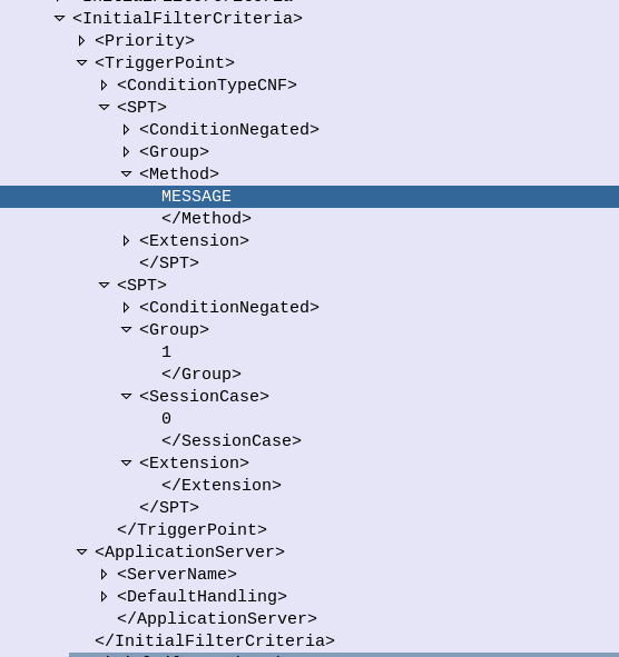
Let’s take a look at an example iFC and then break down the details as to what we’re specifying.
Each rule in an iFC is made up of a Priority, TriggerPoint and ApplicationServer.
So for starters we’ll look at the Priority tag. The Priority tag allows us to have multiple-tiers of priority and multiple levels of matching, For example if we had traffic matching the conditions outlined in this rule (TriggerPoint) but also matching another rule with a lower priority, the lower priority rule would take precedence.
Inside our <TriggerPoint> tag contains the specifics of the rules and how the rules will be joined / matched, which is what we’ll focus on predominantly, and is followed by the <ApplicationServer> which is where we will route the traffic to if the TriggerPoint is matched / triggered.
So let’s look a bit more about what’s going on inside the TriggerPoint.
Each TriggerPoint is made up of Service Point Trigger (SPTs) which are individual rules that are matched or not matched, that are either combined as logical AND or logical OR statements when evaluated.
By using fairly simple building blocks of SPTs we can create a complex set of rules by joining them together.
Service Point Triggers (SPTs)
Let’s take a closer look at what goes on in an SPT. Below is a simple SPT that will match all SIP requests using the SIP MESSAGE method request type:
So as you may have guessed, the <Method> tag inside the SPT defines what SIP request method we’re going to match.
But Method is only one example of the matching mechanism we can use, but we can also match on other attributes, such as Request URI, SIP Header, Session Case (Mobile Originated vs Mobile Terminated) and Session Description such as SDP.
Or an example of a SPT for anything Originating from the Subscriber utilizing the <SessionCase> tag inside the SPT.
Having <Header> will match if the header is present, while the optional Content tag can be used to match
In terms of the Content this is matched using Regular Expressions, but in this case, not so regular regular expressions. 3GPP selected Extended Regular Expressions (ERE) to be used (IEEE POSIX) which are similar to the de facto standard PCRE Regex, but with a few fewer parameters.
Condition Negated
The <ConditionNegated> tag inside the SPT allows us to do an inverse match.
In short it will match anything other than what is specified in the SPT.
For example if we wanted to match any SIP Methods other than MESSAGE, setting <ConditionNegated>1</ConditionNegated> would do just that, as shown below:
Finally the <Group> tag allows us to group together a group of rules for the purpose of evaluating. We’ll go into it more in in the below section.
ConditionTypeCNF / ConditionTypeDNF
As we touched on earlier, <TriggerPoints> contain all the SPTs, but also, very importantly, specify how they will be interpreted.
SPTs can be joined in AND or OR conditions.
For some scenarios we may want to match where METHOD is MESSAGE and RequestURI is sip:[email protected], which is different to matching where the METHOD is MESSAGE or RequestURI is sip:[email protected].
This behaviour is set by the presence of one of the ConditionTypeCNF (Conjunctive Normal Form) or ConditionTypeDNF (Disjunctive Normal Form) tags.
If each SPT has a unique number in the GroupTag and ConditionTypeCNF is set then we evaluate as AND.
If each SPT has a unique number in the GroupTag and ConditionTypeDNF is set then we evaluate as OR.
Let’s look at how the below rule is evaluated as AND as ConditionTypeCNF is set:
This means we will match if the method is MESSAGE and Session Case is 0 (Mobile Originated) as each SPT is in a different Group which leads to “and” behaviour.
If we were to flip to ConditionTypeDNF each of the SPTs are evaluated as OR.
When it comes to setting up dedicated bearers, the Flow-Description AVP is perhaps the most important,
The specially encoded string (IPFilterRule) in the FlowDescription AVP is what our P-GW (Ok, our PCEF) uses to create Traffic Flow Templates to steer certain types of traffic down Dedicated Bearers.
So let’s take a look at how we can lovingly craft an artisanal Flow-Description.
The contents of the AVP are technically not a string, but a IPFilterRule.
IPFilterRules are actually defined in the Diameter Base Protocol (IETF RFC 6733), where we can learn the basics of encoding them,
Which are in turn based loosely off the ipfw utility in BSD.
They take the format:
action dir proto from src to dst
The action is fairly simple, for all our Dedicated Bearer needs, and the Flow-Description AVP, the action is going to be permit. We’re not blocking here.
The direction (dir) in our case is either in or out, from the perspective of the UE.
Next up is the protocol number (proto), as defined by IANA, but chances are you’ll be using 17 (UDP) or 6 (TCP) in most scenarios.
The from value is followed by an IP address with an optional subnet mask in CIDR format, for example from 10.45.0.0/16would match everything in the 10.45.0.0/16 network. Following from you can also specify the port you want the rule to apply to, or, a range of ports, For example to match a single port you could use 10.45.0.0/16 1234 to match anything on port 1234, but we can also specify ranges of ports like 10.45.0.0/16 0 – 4069 or even mix and match lists and single ports, like 10.45.0.0/16 5060, 1000-2000
Protip: using any is the same as 0.0.0.0/0
Like the from, the tois encoded in the same way, with either a single IP, or a subnet, and optional ports specified.
And that’s it!
Keep in mind that Flow-Descriptions are typically sent in pairs as a minimum, as you want to match the traffic into and out of the network (not just one way), but often there can be quite a few sent, in order to match all the possible traffic that needs to be matched that may be across multiple different subnets, etc.
There is an optional Options parameter that allows you to set things like to only apply the rule to open TCP sessions, fragmentation, etc, although I’ve not seen this implemented in the wild.
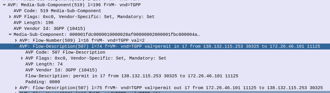
Example IP filter Rules
permit in 6 from 10.98.254.0/24 5061 to 10.98.0.0/24 5060
permit out 6 from 10.98.254.0/24 5060 to 10.98.0.0/24 5061

permit in 6 from any 80 to 172.16.1.1 80
permit out 6 from 172.16.1.1 80 to any 80

permit in 17 from 10.98.254.0/24 50000-60100 to 10.98.0.0/24 50000-60100
permit out 17 from 10.98.254.0/24 50000-60100 to 10.98.0.0/24 50000-60100

permit in 17 from 10.98.254.0/24 5061, 5064 to 10.98.0.0/24  5061, 5064
permit out 17 from 10.98.254.0/24 5061, 5064 to 10.98.0.0/24  5061, 5064

permit in 17 from 172.16.0.0/16 50000-60100, 5061, 5064 to 172.16.0.0/16  50000-60100, 5061, 5064
permit out 17 from 172.16.0.0/16 50000-60100, 5061, 5064 to 172.16.0.0/16  50000-60100, 5061, 5064
As Open5Gs has introduced network slicing, which led to a change in the database used,
Alas many users had subscribers provisioned in the old DB schema and no way to migrate the SDM data between the old and new schema,
If you’ve created subscribers on the old schema, and now after the updates your Subscriber Authentication is failing, check out this tool I put together, to migrate your data over.