Monthly Archives: June 2019

Diameter Packet Structure

We talked a little about what the Diameter protocol is, and how it’s used, now let’s look at the packets themselves.

Each Diameter packet has at a the following headers:
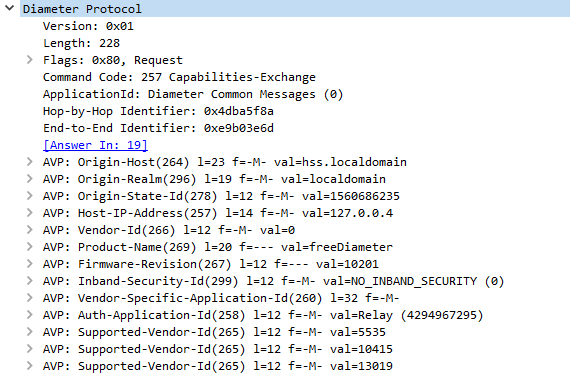
Version

This 1 byte field is always (as of 2019) 0x01 (1)

Length

3 bytes containing the total length of the Diameter packet and all it’s contained AVPs.

This allows the receiver to know when the packet has ended, by reading the length and it’s received bytes so far it can know when that packet ends.

Flags

Flags allow particular parameters to be set, defining some possible options for how the packet is to be handled by setting one of the 8 bits in the flags byte, for example Request Set, Proxyable, Error, Potentially Re-transmitted Message,

Command Code

Each Diameter packet has a 3 byte command code, that defines the method of the request,

The IETF have defined the basic command codes in the Diameter Base Protocol RFC, but many vendors have defined their own command codes, and users are free to create and define their own, and even register them for public use.

3GPP have defined a series of their own command codes.

Application ID

To allow vendors to define their own command codes, each command code is also accompanied by the Application ID, for example the command code 257 in the base Diameter protocol translates to Capabilities Exchange Request, used to specify the capabilities of each Diameter peer, but 257 is only a Capabilities Exchange Request if the Application ID is set to 0 (Diameter Base Protocol).

If we start developing our own applications, we would start with getting an Application ID, and then could define our own command codes. So 257 with Application ID 0 is Capabilities Exchange Request, but command code 257 with Application ID 1234 could be a totally different request.

Hop-By-Hop Identifier

The Hop By Hop identifier is a unique identifier that helps stateful Diameter proxies route messages to and fro. A Diameter proxy would record the source address and Hop-by-Hop Identifier of a received packet, replace the Hop by Hop Identifier with a new one it assigns and record that with the original Hop by Hop Identifier, original source and new Hop by Hop Identifier.

End-to-End Identifier

Unlike the Hop-by-Hop identifier the End to End Identifier does not change, and must not be modified, it’s used to detect duplicates of messages along with the Origin-Host AVP.

AVPs

The real power of Diameter comes from AVPs, the base protocol defines how to structure a Diameter packet, but can’t convey any specific data or requests, we put these inside our Attribute Value Pairs.

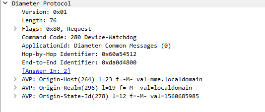
Let’s take a look at a simple Diameter request, it’s got all the boilerplate headers we talked about, and contains an AVP with the username.

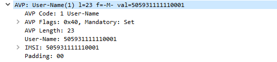
Here we can see we’ve got an AVP with AVP Code 1, containing a username

Let’s break this down a bit more.

AVP Codes are very similar to the Diameter Command Codes/ApplicationIDs we just talked about.

Combined with an AVP Vendor ID they define the information type of the AVP, some examples would be Username, Session-ID, Destination Realm, Authentication-Info, Result Code, etc.

AVP Flags are again like the Diameter Flags, and are made up a series of bits, denoting if a parameter is set or not, at this stage only the first two bits are used, the first is Vendor Specific which defines if the AVP Code is specific to an AVP Vendor ID, and the second is Mandatory which specifies the receiver must be able to interpret this AVP or reject the entire Diameter request.

AVP Length defines the length of the AVP, like the Diameter length field this is used to delineate the end of one AVP.

AVP Vendor ID

If the AVP Vendor Specific flag is set this optional field specifies the vendor ID of the AVP Code used.

AVP Data

The payload containing the actual AVP data, this could be a username, in this example, a session ID, a domain, or any other value the vendor defines.

AVP Padding

AVPs have to fit on a multiple of a 32 bit boundary, so padding bits are added to the end of a packet if required to total the next 32 bit boundary.

Diameter Basics

3GPP selected Diameter protocol to take care of Authentication, Authorization, and Accounting (AAA).

It’s typically used to authenticate users on a network, authorize them to use services they’re allowed to use and account for how much of the services they used.

In a EPC scenario the Authentication function takes the form verifying the subscriber is valid and knows the K & OP/OPc keys for their specific IMSI.

The Authorization function checks to find out which features, APNs, QCI values and services the subscriber is allowed to use.

The Accounting function records session usage of a subscriber, for example how many sessional units of talk time, Mb of data transferred, etc.

Diameter Packets are pretty simple in structure, there’s the packet itself, containing the basic information in the headers you’d expect, and then a series of one or more Attribute Value Pairs or “AVPs”.

These AVPs are exactly as they sound, there’s an attribute name, for example username, and a value, for example, “Nick”.

This could just as easily be for ordering food; we could send a Diameter packet with an imaginary command code for Food Order Request, containing a series of AVPs containing what we want. The AVPs could belike Food: Hawian Pizza, Food: Garlic Bread, Drink: Milkshake, Address: MyHouse.
The Diameter server could then verify we’re allowed to order this food (Authorization) and charge us for the food (Accounting), and send back a Food Order Response containing a series of AVPs such as Delivery Time: 30 minutes, Price: $30.00, etc.

Diameter packets generally take the form of a request – response, for example a Capabilities Exchange Request contains a series of AVPs denoting the features supported by the requester, which is sent to a Diameter peer. The Diameter peer then sends back a Capabilities Exchange Response, containing a series of AVPs denoting the features that it supports.

Diameter is designed to be extensible, allowing vendors to define their own type of AVP and Diameter requests/responses and 3GPP have defined their own types of messages (Diameter Command Codes) and types of data to be transferred (AVP Codes).

LTE/EPC relies on Diameter and the 3GPP/ETSI defined AVP / Diameter Packet requests/responses to form the S6a Interface between an MME and a HSS, the Gx Interface between the PCEF and the PCRF, Cx Interface between the HSS and the CSCF, and many more interfaces used for Authentication in 3GPP networks.

Qos in LTE (4G) – ARP

ARP in LTE is not the Ethernet standard for address resolution, but rather the Allocation and Retention Policy.

A scenario may arise where on a congested cell another bearer is requested to be setup.

The P-GW, S-GW or eNB have to make a decision to either drop an existing bearer, or to refuse the request to setup a new bearer.

The ARP value is used to determine the priority of the bearer to be established compared to others,

For example a call to an emergency services number on a congested cell should drop any other bearers so the call can be made, thus the request for bearer for the VoLTE call would have a higher ARP value than the other bearers and the P-GW, S-GW or eNB would drop an existing bearer with a lower ARP value to accommodate the new bearer with a higher ARP value.

ARP is only used when setting up a new bearer, not to determine how much priority is given to that bearer once it’s established (that’s defined by the QCI).

QoS in LTE (4G) – MBR/AMBR/APN-MBR

MBR stands for Maximum Bit Rate, and it defines the maximum rate traffic can flow between a UE and the network.

It can be defined on several levels:

MBR per Bearer

This is the maximum bit rate per bearer, this rate can be exceeded but if it is exceeded it’s QoS (QCI) values for the traffic peaking higher than the MBR is back to best-effort.

AMBR

Aggregate Maximum Bit Rate – Maximum bit rate of all Service Data Flows / Bearers to and from the network from a single UE.

APN-MBR

The APN-MBR allows the operator to set a maximum bit rate per APN, for example an operator may choose to limit the MBR for subscriber on an APN for a MVNO to give it’s direct customers a higher speed.

(This is only applied to Non-GBR bearers)

QoS in LTE (4G) – QCI

The QCI (Quality Class Indicator) is a value of 0-9 to denote the service type and the maximum delays, packet loss and throughput the service requires.

Different data flows have different service requirements, let’s look at some examples:

A VoLTE call requires low latency and low packet loss, without low latency it’ll be impossible to hold a conversation with long delays, and with high packet loss you won’t be able to hear each other.

On the other hand a HTTP (Web) browsing session will be impervious to high latency or packet loss – the only perceived change would be slightly longer page load times as lost packets are resent and added delay on load of a few hundred ms.

So now we understand the different requirements of data flows, let’s look at the columns in the table above so we can understand what they actually signify:

GBR

Guaranteed Bit Rate bearers means our eNB will reserve resource blocks to carry this data no matter what, it’ll have those resource blocks ready to transport this data.

Even if the data’s not flowing a GBR means the resources are reserved even if nothing is going through them.

This means those resource blocks can’t be shared by other users on the network. The Uu interface in the E-UTRAN is shared between UEs in time and frequency, but with GBR bearers parts of this can be reserved exclusively for use by that traffic.

Non-GBR

With a Non-GBR bearer this means there is no guaranteed bit rate, and it’s just best effort.

Non-GBR traffic is scheduled onto resource blocks when they’re not in use by other non-GBR traffic or by GBR traffic.

Priority

The priory value is used for preemption by the PCRF.

The lower the value the more quickly it’ll be processed and scheduled onto the Uu interface.

Packet Delay Budget

Maximum allowable packet delay as measured from P-GW to UE.

Most of the budget relates to the over-the-air scheduling delays.

The eNB uses the QCI information to make its scheduling decisions and packet prioritisation to ensure that the QoS requirements are met on a per-EPS-bearer basis.

(20ms is typically subtracted from this value to account for the radio propagation delay on the Uu interface)

Packet Error Loss Rate (PELR)

This is packets lost on the Uu interface, that have been sent but not confirmed received.

The PELR is an upper boundary for how high this can go, based on the SDUs (IP Packets) that have been processed by the sender on RLC but not delivered up to the next layers (PDCP) by the receiver.

(Any traffic bursting above the GBR is not counted toward the PELR)

(The list is now larger than 0-9 with 3GPP adding extra QCI values for MCPTT, V2X, etc, the full list is available here in table 6.1.7A)

QoS in LTE (4G) – GBR & Non-GBR Bearers

GBR is a confusing concept at the start when looking at LTE but it’s actually kind of simple when we break it down.

GBR stands for Guaranteed Bit Rate, meaning the UE is guaranteed a set bit rate for the bearer.

The default bearer is always a non-GBR bearer, with best effort data rates.

Let’s look at non-GBR bearers to understand the need for GBR bearers:

As the Uu (Air) interface is shared between many UEs, each is able to transfer data. Let’s take an example of a cell with two UEs in it and not much bandwidth available.

If UE1 and UE2 are both sending the same amount of data it’ll be evenly split between the two.

But if UE1 starts sending a huge amount of data (high bit rate) this will impact on the other UEs in the cells ability to send data over the air as it’s a shared resource.

So if UE2 needs to send a stream of small but important data over the air interface, while UE2 is sending huge amounts of data, we’d have a problem.

To address this we introduce the concept of a Guaranteed Bit Rate. We tell the eNB that the bearer carrying UE2’s small but important data needs a Guaranteed Bit Rate and it reserves blocks on the air interface for UE2’s data.

So now we’ve seen the need for GBR there’s the counter point – the cost.

While UE1 can still continue sending but the eNB will schedule fewer resource blocks to it as it’s reserved some for UE2’s data flow.

If we introduced more and more UEs each requiring GBR bearers, eventually our non-GBR traffic would simply not get through, so GBR bearers have to be used sparingly.

Note: IP data isn’t like frame relay or circuit switched data that’s consistent, bit rate can spike and drop away all the time. GBR guarantees a minimum bit rate, which is generally tuned to the requirements of the data flow. For example a GBR for a Voice over IP call would reserve enough for the media (RTP stream) but no more, so as not to use up resources it doesn’t need.

NAT solutions used in VoIP

NAT is still common in Voice networks, and while we’re all awaiting the full scale adoption of IPv6, it’s still going to be a thing for some time.

I thought I’d dive into some of the NAT “solutions” that are currently in use.

Old RFC 3489 Definitions

These were the first NAT implementations used, and are still often used today.

Full cone NAT

A request from a private address is mapped to a public address and a publicly available port.

Traffic can be sent from any external device to this public address / port combination, and will be sent the internal device.

This is often statically setup, where you’d log into your router and put a NAT rule saying “Traffic on Port 5060 I want forwarded to my desk phone on 192.168.1.2” for example, and is sometimes just called a “Port forward”.

This can work fine if you’ve just got one unchanging internal address, but starts to have issues with multiple devices or dynamically assigned IPs.

Restricted Cone NAT

A request from a private address is mapped to a public address.

Traffic sent to this public address from an allowed IP will be routed to the internal device, regardless of port used.

Port Restricted Cone

Like restricted cone but only a single port may be used, traffic sent to any other port will not be routed to the internal device.

Symmetric NAT

Each request to an external destination gets a unique Public IP / Port combination to be used only by that destination, and each new request with a different source port on the internal side, or different destination on the external side, sets up a new NAT path.

RFC 5389 NAT Definitions

Endpoint Independent Mapping

Each request to an external destination gets the same public IP address / Port combination used for the outbound traffic.

Return traffic from the external destination is routed based on the source address, to the internal IP of the originating user.

It’s possible to have multiple internal devices communicating with multiple external destinations, using the same public IP address / port combination for each of them.

The source IP address of the traffic back from the external destination is used to map the path back to the internal IP.

This is efficient (doesn’t need to keep using outbound ports on the public IP) but means that it’ll only work to the requested external destination’s IP.

If you register to a SIP server on one IP, and media comes in on another, an Endpoint Independent Mapping NAT will see you with one-way audio.

Address Dependant Mapping

Each request to an external destination gets a unique public IP address / port combination used for outbound traffic.

It is reused for packets sent to the same destination, regardless of which destination port is used.

Address and Port Dependant Mapping

Same as Address Dependant Mapping but a new mapping is created for each destination and port.

Numbering Systems in Australia: E.164 vs 0-NDC-SN

You’ll often see numbers listed in different formats, which often leads to confusion.

Australian SIP networks may format numbers in either 0NDC-SN or E.164 format, leading some confusion. There’s no “correct” way, ACMA format in 0-NDC-SN, while most Australian tier 1 carriers store the records in E.164 format.

There’s no clear standard, so it’s always best to ask.

Let’s say my number is in Melbourne and is 9123 4567,

This could be expressed in Subscriber Number (SN) format:

9123 4567

The problem is a caller from Perth calling that number wouldn’t get through to me, there’s a good chance they’d get a totally unrelated business.

To stop this we can add the National Destination Code (NDC), for Victoria / Tasmania this is 3, however when dialling domestically a 0 is prefixed.

The leading 0 is a carry over from the days of step-by-step based switching, which had technical and physical design constraints that dictated the dialling plan we see today, which I’ll do a post about another day.

So to put it in 0-NDC-S format we’d list

03 9123 4567

But an international caller wouldn’t be able to reach this from their home country, they’d need to add the Country Code (CC) which for Australia is 61, so they’d dial the CC-NDC-SN

So they’d dial 61 3 9123 4567

This formatting is called E.164, defined by the ITU in The international public telecommunication numbering plan,

Sometimes this is listed with the plus symbol in front of it, like

+61 3 9123 4567

Each country has it’s own international dialling prefix, and the plus symbol is to be replaced by the international dialling prefix used in the calling country. In Australia, we replace the + with 0011, but it’s different from country to country.

RF Planning with Forsk Atoll - Importing environmental data

Forsk Atoll – WMS Map Tiles

A hack I found useful to add Google Maps / Google Satelite View / Bing Maps / Bing Arial / Open Street Maps in Forsk Atoll.

Close Atoll,

Go to C -> Program Files -> Atoll

Edit the file named atoll.ini

Paste the following into it:

[OnlineMaps]
Name1 = OpenStreetMap Standard Map
URL1 = http://a.tile.openstreetmap.org/%z/%x/%y.png
Name2 = MapQuest Open Aerial
URL2 = http://otile1.mqcdn.com/tiles/1.0.0/sat/%z/%x/%y.jpg
Name3 = 2Gis
URL3 = http://static.maps.api.2gis.ru/1.0?c...z&size=256,256
Name4 = 2Gis without logo
URL4 = http://tile2.maps.2gis.com/tiles?x=%x&y=%y&z=%z&v=37 
Name5 = Bing Aerial
URL5 = http://ecn.t3.tiles.virtualearth.net.../a%q.jpg?g=392
Name6 = Bing Hybrid
URL6 = http://ecn.t3.tiles.virtualearth.net.../h%q.jpg?g=392
Name7 = Bing Road
URL7 = http://ecn.t3.tiles.virtualearth.net.../r%q.jpg?g=392
Name8 = Yandex Road
URL8 = http://static-maps.yandex.ru/1.x/?ll...=%z&l=map&key=
Name9 = Yandex Aerial
URL9 = http://static-maps.yandex.ru/1.x/?ll...=%z&l=sat&key=
Name10 = Yandex Hybrid
URL10 = http://static-maps.yandex.ru/1.x/?ll...l=sat,skl&key=
Name11 = ArcGIS
URL11 = http://services.arcgisonline.com/Arc...e/%z/%y/%x.png
Name12 = opencyclemap
URL12 = http://tile.opencyclemap.org/cycle/%z/%x/%y.png
Name13 = Google Terrain
URL13 = http://mt.google.com/vt/lyrs=t&hl=en&x=%x&y=%y&z=%z
Name14 = Google Map
URL14 = http://mt.google.com/vt/lyrs=m&hl=en&x=%x&y=%y&z=%z
Name15 = Google Hybrid (Map + Terrain)
URL15 = http://mt.google.com/vt/lyrs=p&hl=en&x=%x&y=%y&z=%z
Name16 = Google Hybrid (Map + Satellite)
URL16 = http://mt.google.com/vt/lyrs=y&hl=en&x=%x&y=%y&z=%z
Name17 = Google Satellite
URL17 = http://mt.google.com/vt/lyrs=m&hl=en&x=%x&y=%y&z=%z
Name18 = Google Scheme
URL18 = http://mt.google.com/vt/lyrs=h&hl=en&x=%x&y=%y&z=%z
Name19 = Google Scheme2 
URL19 = http://mt.google.com/vt/lyrs=r&hl=en&x=%x&y=%y&z=%z

Save and open Atoll,

Open the Geo Tab,

Right click on Online Maps, click “New”

Select the map source (In this example I’m using OSM) & hit Ok.

Enable the Online Map layer by ticking the layer.

Bam, done.

RF Planning with Forsk Atoll - Laying out environmental data