Tag Archives: MCS

IMTx: NET02x (4G Network Essentials) – Radio Interface – 4. Transmission Reliability in Radio

These are my lecture notes from IMT’s NET02x (4G Network Essentials) course, I thought I’d post them here as they may be useful to someone. You can find my complete notes here.

Radio is always subject to interference, we talked before about how coding is used on the physical layer to try and correct these errors.

The MAC layer (Media Access Control) handles error correction, and performs multiplexing of services to the same UE at the same time (multiplexing).

Automatic Repeat Request (ARQ)

When data is sent a CRC (Cyclic Redunancy Check) is added, containing a checksum equivalent of the data contained in the message.

The receiver runs the same CRC calculation on the data, and if the CRC value is not equal to the CRC value it received it knows the data is not correct/complete.

There are 3 scenarios shown below:

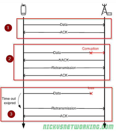
Scenario 1 – Data is sent and the CRC calculated by the sender matches the CRC calculated by the reciver.
An ACK is sent to confirm the data was received correctly.

Scenario 2 – Data is sent and the CRC calculated by the sender does not match the CRC calculated by the receiver.
The receiver sends a NACK (Negative Ack),
The sender sends the data again, the CRC this time matches, so an ACK is sent to confirm the data was received correctly.

Scenario 3 – Data is sent by not ACK or NACK was received. This could mean the data was not received, or the ACK/NACK was not received.
The sender then sends the message again.
This process is repeated a set number of times after which if no response is received the sender gives up.

Acknowledgement

This technique is called Send and Wait ARQ, because the sender must send the data and wait for an ACK/NACK, and will automatically request re-transmission.

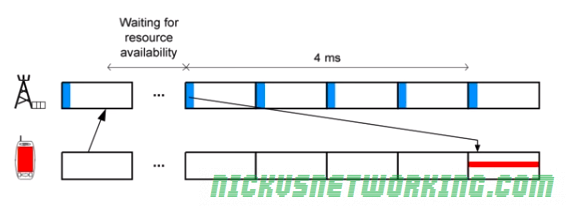
Because CRC may take some time to calculate the ACK/NACK is given time to process by the receiver and the ACK/NACK is sent 4ms after it was received.

If a NACK is received the data is re-transmitted 4ms after receipt of the NACK.

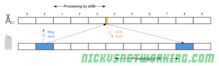
This means all up it takes up to 8ms (8 subframes) to send the data, wait for the response and send again if needed. During this time no other data would be sent.

As you can imagine this isn’t a particularly efficient use of time or resources, so the EUTRAN specs define 8 Send and Wait processes in parallel.

While the first process is blocked waiting for an ACK/NACK, another process can transmit. This is called Parallel Send and Wait.

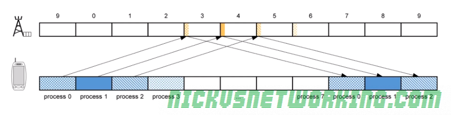
The problem with this is it can lead to data being received out of sequence, as if data is sent and a re-transmission is needed (NACK received by sender) that data will be received after the data sent 8 frames after it.

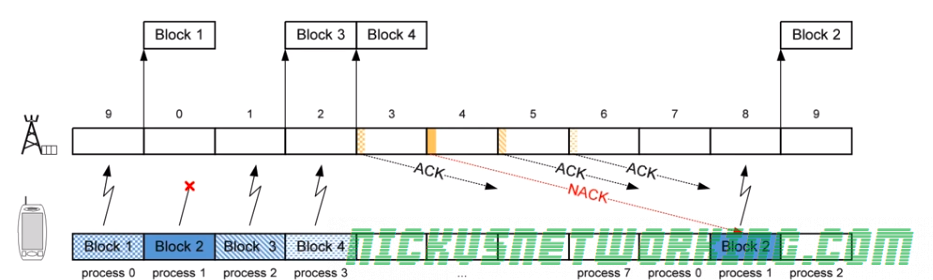
Here we can see Block 2 was lost, a NACK was sent and a re-transmission occurs 8 subframes later, long after Block 3 and Block 4 were received.

The MAC layer does not deal with re-sequencing, this is managed by the RLC layer above the MAC layer.

Hybrid ARQ

LTE relies on Hybrid ARQ. To increase redundancy and increase the possibility of decoding a corrupted message correctly.

We talked about coding – sending multiple copies of the same data and comparing them to find the common features that would indicate correct data, Hybrid ARQ functions in much the same way.

To increase error correction performance the receiver keeps the invalid/corrupt messages it sends a NACK for, so it can compare it to the re-transmitted version and hopefully correctly decode the message even if the re-transmission is corrupted.

It is called Hybird because the MAC layer has to communicate to the physical layer to let is know this is a re-transmission and not a new transmission.

Multiplexing on the MAC Layer

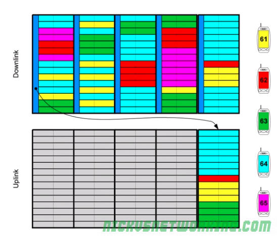
You may use your smartphone (UE) for a voice call while looking up something online and getting push notifications, while these are 3 distinct streams of data, there is only one stream of data to and from the eNB <-> UE.

These different types of data all need to be combined into one “pipe” between the eNB and UE, this is known as multiplexing.

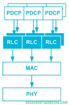
The RLC layer has multiple types of data arranged in logical channels, but this data has to be put into a MAC PDU and sent over the air.

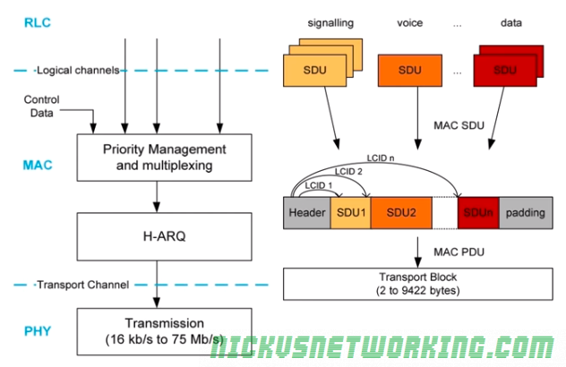
In the standard networking model, data in an upper layer is called SDU “Service Data Units”, and data in a lower layer is called a PDU “Protocol Data Units”.

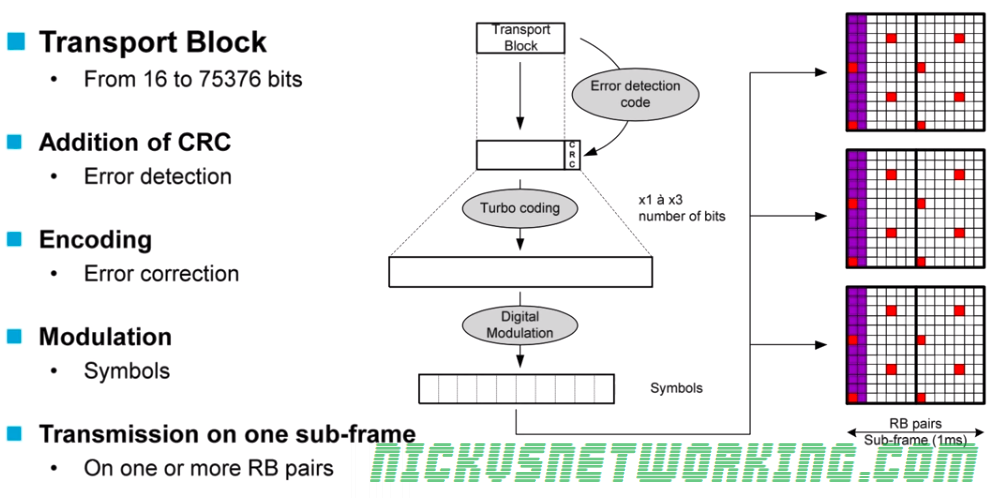
To form the transport blocks the MAC layer must take each of the SDUs from the RLC layer, and put it into the transport block, as show in the image above.

The MAC header contains the delineation of what data is for which SDU on the RLC layer.

IMTx: NET02x (4G Network Essentials) – Radio Interface – 3. Packet Allocation

These are my lecture notes from IMT’s NET02x (4G Network Essentials) course, I thought I’d post them here as they may be useful to someone. You can find my complete notes here.

Allocation Tables

To inform UEs of which resources are allocated to it, the eNB regularly publishes Allocation Tables with this information.

Resources are allocated dynamically, by the eNB to all the UEs it is serving.

Because the eNB manages all the resources, the eNB must inform the UEs which resources are allocated to which UEs.

This is broken into two functions:

  • A UE must be able to be informed it’s going to receive data (downlink) and be allocated the resources for it.
  • A UE must be able to request resources from the eNB to send data (uplink) and be allocated resources for it.

The eNB manages all resource allocation, for downlink and uplink, when they are needed. This is done through an allocation table published by the eNB every subframe (1ms).

There are two allocation tables – One for uplink, one for downlink.

Addressing on the Radio Interface – RNTI

As an allocation table needs to allocate resources to each UE it needs a way to address them.

GUTI, IMSI, TMSI etc, are all too long (allocation tables are published every subframe so need to be a small as possible).

Instead for addressing in the allocation tables as RNTI – Radio Network Temporary Identifier is issued by the eNB to each UE it is serving, the RNTI is issued by the eNB and only valid for that cell, if the user moves to another cell served by another eNB another RNTI is allocated by that eNB.

The RNTI is 16 bits long, meaning it can store 65,536 decimal values. (65,536 UEs)

Allocation on Downlink

Resource allocation for the downlink is managed by the eNB, which publishes allocation tables every subframe defining which resource blocks are allocated to which UE.

The resource blocks contains the RNTI of each UE to receive data and the resource blocks it’s data will be contained in.

Each UE listens for the allocation tables published in each subframe, and if the UE sees it’s own RNTI in the allocation table it listens on the resource blocks allocated to it.

In the example above we can see the allocation table in the dark blue colour, published every 1ms (aka every subframe).

In this example the UE that has been assigned RNTI 63 (represented in green) has got resource blocks 12 & 13 assigned to it, so will listen on 12 and 13 to get it’s downlink data.

Because UEs only listen for the allocation tables and the resource blocks assigned to them, it leads to power savings on the UE as they don’t all need to listen / decode to all resource blocks. Power savings on the UE translate to better battery efficiency.

The UE with RNTI 61 for example, does not get allocated any resource blocks in the downlink in the example allocation table, so it listens for the allocation table and then goes into standby mode until the next allocation table is published.

The allocation tables are contained in the Physical Downlink Control Channel (PDCCH) a channel used only by the eNB to broadcast resource allocation tables and control data.

The actual downlink data for each UE is contained in the Physical Downlink Shared Channel (PDSCH)

Allocation in the Uplink

Allocation in the uplink is similar to allocation in the downlink, however there are some important differences.

  • The UE must request the resources from the eNB and wait for them to be allocated in the next uplink resource block.
  • There is a 4ms delay between a resource block being allocated in an allocation table by the eNB for the uplink and it being used by the UE to send data. This gives the UE time to get the data ready to go into the resource block.

The UE requests a resource from the eNB (covered later) and the eNB publishes an allocation table in the next subframe, however this allocation table is to be used in 4 subframes time.

The UE then buffers this allocation table and uses it in 4 subframes time.

By having this delay in using the resource table / allocating resource tables in advance, it allows our UEs to prepare the message for transmission, encode it, modulate it, etc.

The image below shows the UE in red requesting a resource for uplink from the eNB, the eNB then publishes the allocation table for 4 subframes time, the UE waits for 4 subframes to pass and then the UE transmits using the resources allocated in the allocation table published 4ms prior.

For example in the image below the UE with the RTNI of 64, represented in light blue, has requested a resource to send data (uplink), the eNB publishes an uplink allocation table in the next subframe, and the UE has then 4 subframes to prepare the data for transmission before sending the data using the resources allocated in the allocation table sent to it 4 subframes prior.

Like in the Downlink, Uplink transmissions are managed by a Control Channel and data is contained within a Data Channel.

The Physical Uplink Control Channel (PUCCH) contains the control information and the resource tables for the uplink (to be used in 4 subsframes time), shown in gray.

The data being sent from the UEs is contained in Physical Uplink Shared Channels (PUSCH) allocated 4ms prior in a PUCCH.

When a UE has data to transmit it transmits on the PUCCH to request a resource block for the uplink data.

IMTx: NET02x (4G Network Essentials) – Radio Interface – 2. Resource Blocks & Sub-Frames

These are my lecture notes from IMT’s NET02x (4G Network Essentials) course, I thought I’d post them here as they may be useful to someone. You can find my complete notes here.

As spectrum is sparse and expensive, so it must be used wisely and shared across multiple users.

LTE shares spectrum in both frequency and time.

L

LTE can use bandwidths from 1.4Mhz to 20Mhz, based on the spectrum owned and needs of the area.

Spectrum is divided into sub-carriers, allowing each subcarrier to be allocated to a different user, and these subcarriers are re-allocated by the eNB based on the terminal’s needs.

Resource Element (RE)

A Resource Element is the time and frequency a single symbol can be transmitted on.

Resource Elements are allocated by the eNB to UEs and the UE transmits on it’s allocated resource element one symbol.

The size of the data in the symbol is defined by the MCS used.

One Resource Element is contained within 1 subcarrier of 15kHz lasting 66μ s.

Resource Blocks (RB)

Because resource elements are so small, they’re managed in Resource Blocks.

Each Resource Block lasts 0.5ms with 12 sub carriers on each, allowing for 84 Resource Elements in per Resource Block.

The number of Resource Blocks that can be used is determined by the spectrum available.

As we can calculate a Resource Block occupies 180kHz of bandwidth, how many Resource Blocks we can have is determined by how many will fit into our bandwidth.

A system using the minimum bandwidth of 1.4Mhz will have 6 RBs available (1.4Mhz divides into 6 complete 180kHz RBs), while one using the maximum of 20Mhz will have 100 RBs available.

Not all the REs in an RB can be used by terminals though, many of them are reserved for LTE control channels.

The purple and red blocks are reserved as control channels

Meaning only the white REs shown above can be filled with user traffic.

Sub-Frame

Every 1ms (or 2 Resource Blocks) LTE reallocates the RBs to the terminals that need to communicate.

This means Resource Blocks are allocated in pairs, called a subframe, lasting 1ms.

Subframe, RB, RE Hierarchy

Each subframe is 1ms long and made up of 2 0.5ms Resource Blocks.

Each Resource Block contains 84 Resource Elements, each of which contain one symbol of data.

Resource Allocation in Uplink

When a device needs to transmit data it is allocated one or more resource blocks.

If the number of resource blocks is not enough it can be allocated more in the next subframes.

The amount of data a device can transmit in each subframe is called a Transport Block and is made up of the number of RBs and the modulation (MCS) used.

Table of MCS vs Resource Block Pairs (Subframes) and resulting data throughput rate in bits

The sub frame containing contain data for various terminals is shown below in different colors.

Transmission Chain

Transport Blocks are filled with data based on the Transport Block size.

CRC is added to detect errors.

Data is encoded to help recover data containing errors. (Defined by MCS)

Data is modulated (Using modulation scheme defined by MCS)

Data is transmitted in the user-data part that has been allocated in one or more Resource Block Pairs.