Tag Archives: 5GSA

5GC: The Network Function Repository Function

The Problem

Mobile networks are designed to be redundant and resilient, with N+1 for everything.

Every network element connects to multiple other network elements.

The idea being the network is architected so a failure of any one network element will not impact service.

To take an LTE/EPC example, your eNodeBs connect to multiple MMEs, which in turn connect to multiple HSSs, multiple S-GWs, multiple EIRs, etc.
The problem is when each eNodeB connects to 3 MMEs, and you want to add a 4th MME, you have to go and reconfigure all the eNodeBs to point to the new MME, and all the HSSs to accept that MME as a new Diameter Peer, for example.

The more redundant you make the network, the harder it becomes to change.

This led to development of network elements like Diameter Routing Agents (DRAs) and DNS SRV for service discovery, but ultimately adding and removing network elements in previous generations of mobile core, involved changing a lot of config on a lot of different boxes.

The Solution

The NRF – Network Repository Function serves as a central repository for Network Functions (NFs) on the network.

In practice this means when you bring a new Network Function / Network Element online, you only need to point it at the NRF, which will tell it about other Network Functions on the network, register the new Network Function and let every other interested Network Function know about the new guy.

Take for example adding a new AMF to the network, after bringing it online the only bit of information the AMF really needs to start placing itself in the network, is the details of the NRF, so it can find everything it needs to know.

Our new AMF will register itself to the NRF, advertising what Network Functions it can offer (ie AMF service), and it’ll in turn be able to learn about what Network Functions it can consume – for example our AMF would need to know about the UDMs it can query data from.

It is one of the really cool design patterns usually seen in modern software, that 3GPP have adopted as part of the 5GC.

In Practice

Let’s go into a bit more detail and look at how it looks.

The NRF uses HTTP and JSON to communicate (anything not using ASN.1 is a winner), and looks familiar to anyone used to dealing with RESTful APIs.

Let’s take a look at how an AMF looks when registering to a NRF,

NF Register – Providing the NRF a profile for each NF

In order for the NRF to function it has to know about the presence of all the Network Functions on the network, and what they support. So when a new Network Function comes online, it’s got to introduce itself to the NRF.

It does this by providing a “Profile” containing information about the Network Functions it supports, IP Addresses, versions, etc.

Going back to our AMF example, the AMF sends a HTTP PUT request to our NRF, with a JSON payload describing the functions and capabilities of the AMF, so other Network Functions will be able to find it.

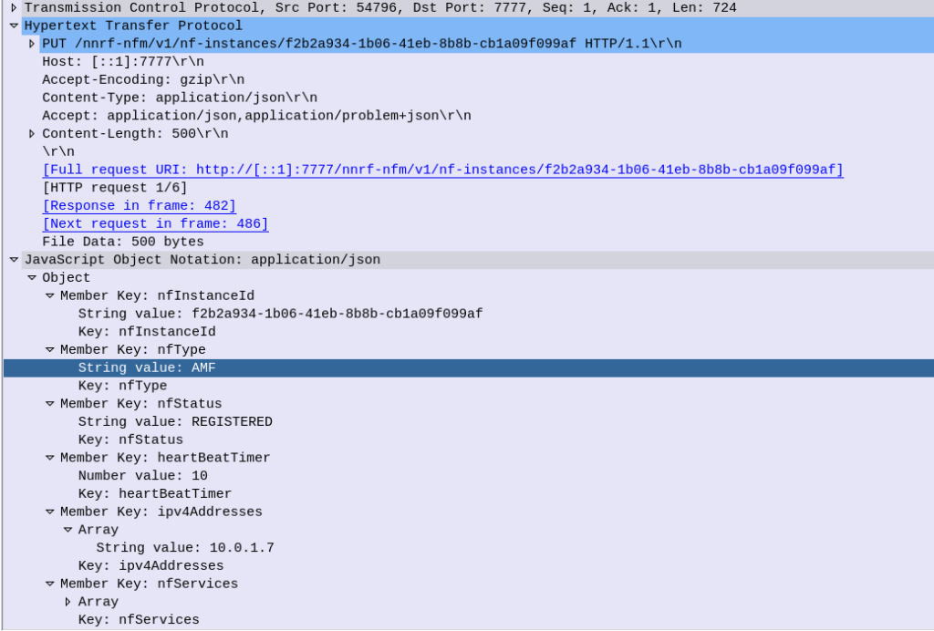
Let’s take a look at what’s in the JSON payload used for the NF Profile.

  • Each Network Function is identified by a UUID – nfInstanceId, in this example it’s value is “f2b2a934-1b06-41eb-8b8b-cb1a09f099af”
  • The nfType (Network Function type) is an AMF, and it’s IP Address is 10.0.1.7
  • The heartBeatTimer sets how often the network function (in this case AMF) sends messages to the NRF to indicate it’s still alive. This prevents a device registering to an NRF and then going offline, and the NRF not knowing.

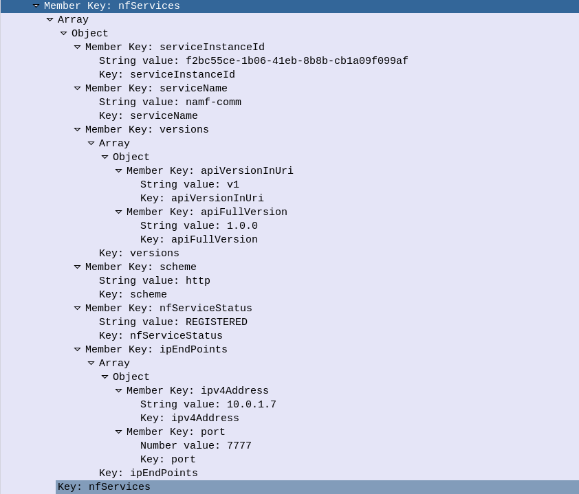
The nfServices key contains an array of services and details of those services, in the below example the key feature is the serviceName which is namf-comm which means the Namf_Communication Service offered by the AMF.

The NRF files this info away for anyone who requests it (more on that later) and in response to this our NRF will indicate (hopefully) that it’s successfully created the entry in its internal database of Network Functions for our AMF, resulting in a HTTP 201 “Created” response back from the NRF to the AMF.

NRF StatusSubscribe – Subscribe & Notify

Simply telling the NRF about the presence of NFs is one thing, but it’s not much use if nothing is done with that data.

A Network Function can subscribe to the NRF to get updates when certain types of NFs enter/leave the network.

Subscribing is done by sending a HTTP POST with a JSON payload indicating which NFs we’re interested in.

Contents of a Subscription message to be notified of all AMFs joining the network

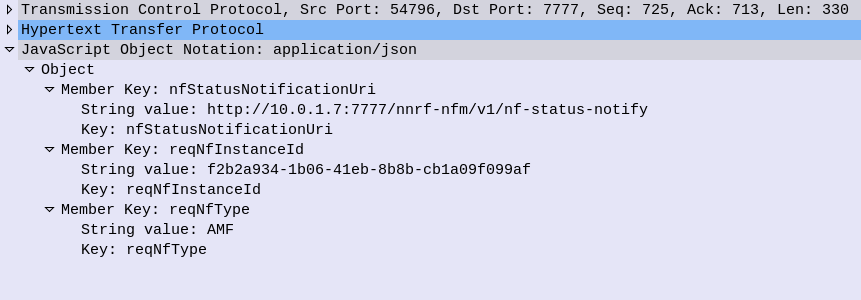
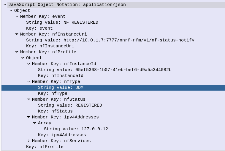
Whenever a Network Function registers on the NRF that related to the type that has been subscribed to, a HTTP POST is sent to each subscriber to let them know.

For example when a UDM registers to the network, our AMF gets a Notification with information about the UDM that’s just joined.

NRF Update – Updating NRF Profiles & Heartbeat

If our AMF wants to update its profile in the NRF – for example a new IP is added to our AMF, a HTTP PATCH request is sent with a JSON payload with the updated details, to the NRF.

The same mechanism is used as the Heartbeat / keepalive mechanism, to indicate the NRF is still there and working.

Summary

The NRF acts as a central repository used for discovery of neighboring network functions.

5GC for EPC Folks – User Plane Traffic

As the standardisation for 5G-SA has been completed and the first roll outs are happening, I thought I’d cover the basic architecture of the 5G Core Network, for people with a background in EPC/SAE networks for 4G/LTE, covering the key differences, what’s the same and what’s new.

This posts focuses on the User Plane side of things, there’s a similar post I’ve written here on the Control Plane side of things.

UPF – User Plane Forwarding

The UPF bridges the external networks (DNs) to the gNodeB serving the UE by encapsulating the traffic into GTP, which has been used in every network since GSM.

Like the P-GW the UPF takes traffic destined to/from external networks and passes it to/from subscribers.

In 5GC these external networks are now referred to as “DN” – Data Networks, instead of by the SGi reference point.

In EPC the Serving-Gateway’s intermediate function of routing traffic to the correct eNB is removed and instead this is all handled by the UPF, along with buffering packets for a subscriber in idle mode.

The idea behind this, is that by removing the S-GW removes extra hops / latency in the network, and allows users to be connected to the best UPF for their needs, typically one located close to the user.

However, there are often scenarios where an intermediate function is required – for example wanting to anchor a session to keep an IP Address allocated to one UPF associated with a user, while they move around the network. In this scenario a UPF can act as an “Session Anchor” (Akin to a P-GW), and pass through “Intermediate UPFs” (Like S-GWs).

Unlike the EPCs architecture, there is no limit to how many I-UPFs can be chained together between the Session Anchoring UPF and the gNB, and this chaining of UPFs allows for some funky routing options.

The UPF is dumb by design. The primary purpose is just to encapsulate traffic destined from external networks to subscribers into GTP-U packets and forward them onto the gNodeB serving that subscriber, and the same in reverse. Do one thing and do it well.

SMF – Session Management Function

So with dumb UPFs we need something smarter to tell them what to do.

Control of the UPFs is handled by the SMF – Session Management Function, which signals using PFCP down to the UPFs to tell them what to do in terms of setting up connections.

While GTP-U is used for handling user traffic, control plane traffic no longer uses GTPv2-C. Instead 5GC uses PFCP – Packet Forwarding Control Protocol. To get everyone warmed up to Control & User Plane separation 3GPP introduced as seen in CUPS into the EPC architecture in Release 14.

This means the interface between the SMF and UPF (the N4 interface) is more or less the same as the interface between a P-GW-C and a P-GW-U seen in CUPS.

When a subscriber connects to the network and has been authenticated, the AMF (For more info on the AMF see the sister post to this topic covering Control Plane traffic) requests the SMF to setup a connection for the subscriber.

Interworking with EPC

For deployments with an EPC and 5GC interworking between the two is of course required.

This is achieved first through the implementation of CUPS (Control & User Plane Separation) on the EPC, specifically splitting the P-GW into a P-GW-C for handing the Control Plane signalling (GTPv2c) and a P-GW-U for the User Plane traffic encapsulated into GTP.

The P-GW-C and P-GW-U communications using PFCP are essentially the same as the N4 interface (between the SMF and the UPF) so the P-GW-U is able to act as a UPF.

This means handovers between the two RATs / Cores is seamless as when moving from an LTE RAT and EPC to a 5G RAT and 5G Core, the same UPF/P-GW-U is used, and only the Control Plane signalling around it changes.

When moving from LTE to 5G RAT, the P-GW-C is replaced by the SMF,
When moving from 5G RAT to LTE, the SMF is replaced by the P-GW-C.
In both scenarios user plane traffic takes the same exit point to external Data Networks (SGi interface in EPC / N6 interface in 5GC).

Interfaces / Reference Points

N3 Interface

N3 interface connects the gNodeB user plane to the UPF, to transport GTP-U packets.

This is a User Plane interface, and only transports user plane traffic.

This is akin to the S1-UP interface in EPC.

N4 Interface

N4 interface connects the Session Management Function (SMF) control plane to the UPF, to setup, modify and delete UPF sessions.

It is a control plane interface, and does not transport User Plane traffic.

This interface relies on PFCP – Packet Forwarding Control Protocol.

This is akin to the SxB interface in EPC with CUPS.

N6 Interface

N6 interface connects the UPF to External Data Networks (DNs), taking packets destined for Subscribers and encapsulating them into GTP-U packets.

This is a User Plane interface, and only transports user plane traffic.

This is akin to the SGi interface in EPC.

N9 Interface

When Session Anchoring is used, and Intermediate-UPFs are used, the connection between these UPFs uses the N9 interface.

This is only used in certain scenarios – the preference is generally to avoid unnecessary hops, so Intermediate-UPF usage is to be avoided where possible.

As this is a User Plane interface, it only transports user plane traffic.

When used this would be akin to the S5 interface in EPC.

N11 Interface

SMFs need to be told when to setup / tear down connections, this information comes from the AMF via the N11 interface.

As this is a Control Plane interface, it only transports control plane traffic.

This is similar to the S11 interface between the MME and the S-GW in EPC, however it would be more like the S11 if the S11 terminated on the P-GW.