While vCenter doesn’t really do contexts / mutli-tenants / VPCs like the hyperscalers, there are simple (ish) ways to do context separation inside VMware vCenter.
This means you can have a user who only has access to say a folder of VMs, but not able to see VMs outside of that folder.
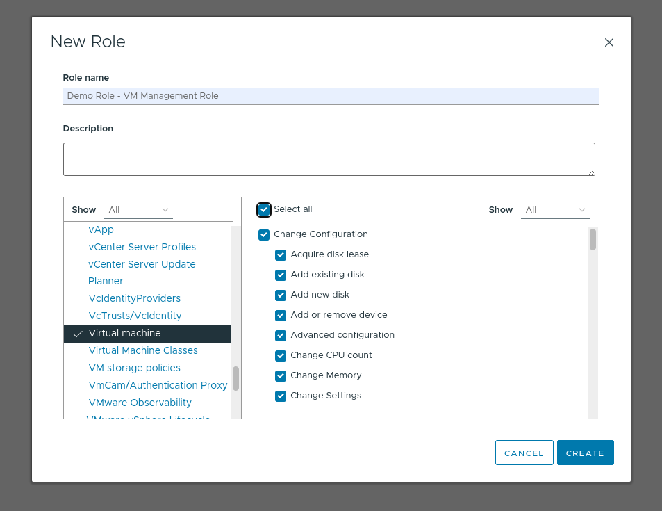
Create a new Role inside vCenter from Administration -> Roles -> Add
Give the role all Virtual Machine privileges:
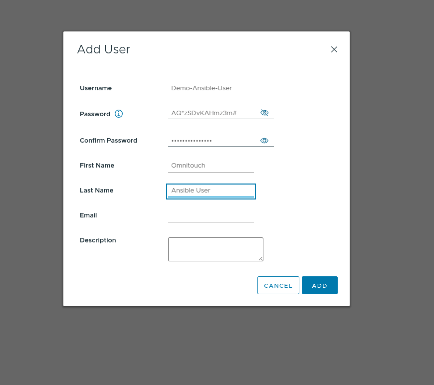
Create a new account (Can be on AD if you’re not using Local accounts, this is just our lab so I’ve created it as a Local account) for the user. We’re using this account for Ansible so we’ve used “Demo-Ansible-User” as the username
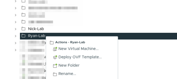
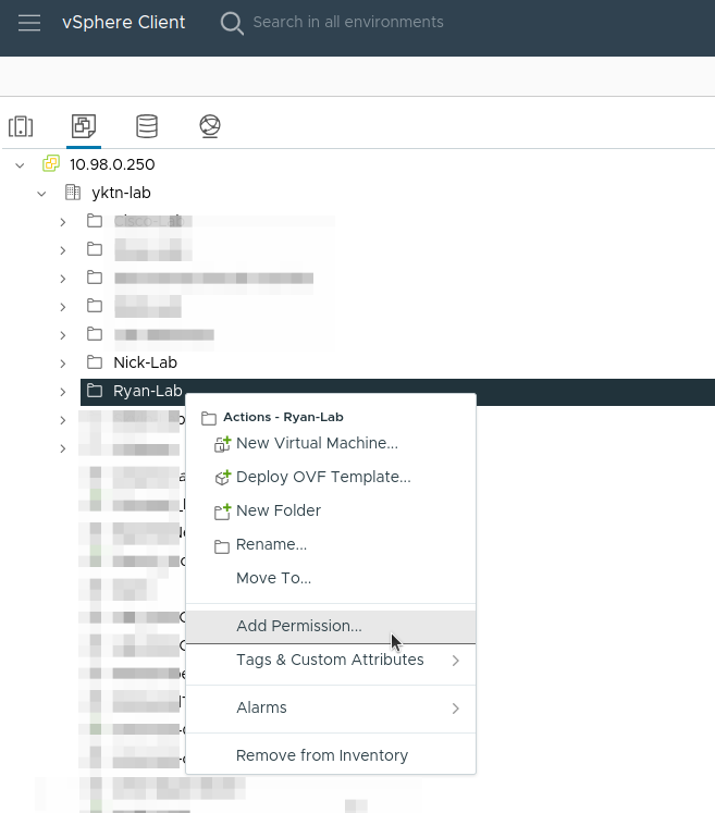
Now create a folder for the group of VMs, or pick an existing folder you want to give access to.
Right click on the folder and select “Add Permission”.
We give permission to that user with that role on the folder and make sure you tick “Propagate to children” (I missed this step before and had to repeat it):
If you are using templates, make sure the template is either in the folder, or apply the same permission to the template, by right clicking on it, Add Permission, same as this.
Finally you should be able to log in as that user and see the template, and clone it from the web UI, or create VMs but only within that folder.
Recently I’ve been using Wireguard to fix the things I once used IPsec for.
It was merged into the Mainline Linux kernel late last year, and then in RouterOS 7.0beta7 (2020-Jun-3) the system kernel on RouterOS was upgraded to version 5.6.3 which contains Wireguard support.
Unfortunately this feature is going to stay in the Unstable / Development releases for the time being until a kernel update is done for the stable release to 5.5.3 or higher, but for now I thought I’d try it out.
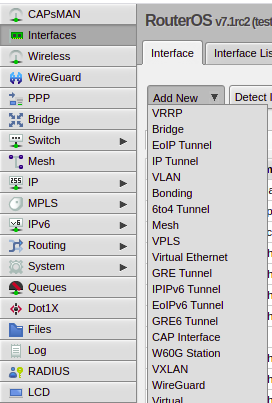
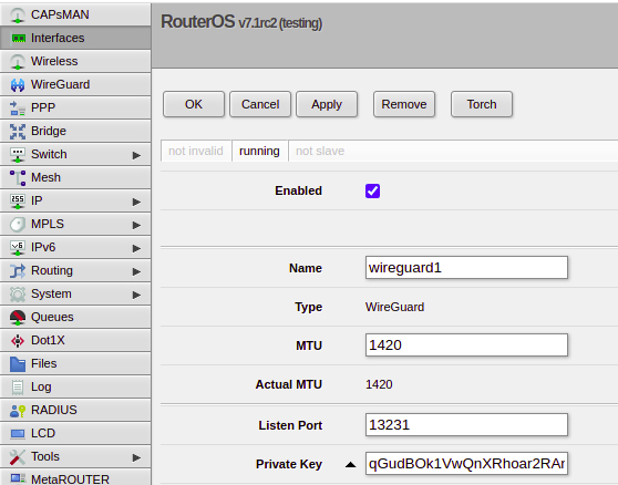
After loading a beta version of the firmware, under Interfaces I have the option to add a Wireguard interface, for clients to connect to my Mikrotik using Wireguard.
It’s nice and simple to see the public/private key pair (a new key pair is generated for each Wireguard instance which is nifty) that we an use to authenticate / be authenticated.
If we want to configure remote peers, we do this by jumping over to the Wireguard -> Peers tab, allowing us to setup Peers from here.
Obviously routing and firewalls remain to be setup, but I love the simplicity of Wireguard, and in the RouterOS implimentation this is kept.
So I’ve been waxing lyrical about how cool in the NRF is, but what about how it’s secured?
A matchmaking service for service-consuming NFs to find service-producing NFs makes integration between them a doddle, but also opens up all sorts of attack vectors.
Theoretical Nasty Attacks (PoC or GTFO)
Sniffing Signaling Traffic: A malicious actor could register a fake UDR service with a higher priority with the NRF. This would mean UDR service consumers (Like the AUSF or UDM) would send everything to our fake UDR, which could then proxy all the requests to the real UDR which has a lower priority, all while sniffing all the traffic.
Stealing SIM Credentials: Brute forcing the SUPI/IMSI range on a UDR would allow the SIM Card Crypto values (K/OP/Private Keys) to be extracted.
Sniffing User Traffic: A dodgy SMF could select an attacker-controlled / run UPF to sniff all the user traffic that flows through it.
Obviously there’s a lot more scope for attack by putting nefarious data into the NRF, or querying it for data gathering, and I’ll see if I can put together some examples in the future, but you get the idea of the mischief that could be managed through the NRF.
This means it’s pretty important to secure it.
OAuth2
3GPP selected to use common industry standards for HTTP Auth, including OAuth2 (Clearly lessons were learned from COMP128 all those years ago), however OAuth2 is optional, and not integrated as you might expect. There’s a little bit to it, but you can expect to see a post on the topic in the next few weeks.
3GPP Security Recommendations
So how do we secure the NRF from bad actors?
Well, there’s 3 options according to 3GPP:
Option 1 – Mutual TLS
Where the Client (NF) and the Server (NRF) share the same TLS info to communicate.
This is a pretty standard mechanism to use for securing communications, but the reliance on issuing certificates and distributing them is often done poorly and there is no way to ensure the person with the certificate, is the person the certificate was issued to.
3GPP have not specified a mechanism for issuing and securely distributing certificates to NFs.
Option 2 – Network Domain Security (NDS)
Split the network traffic on a logical level (VLANs / VRFs, etc) so only NFs can access the NRF.
Essentially it’s logical network segregation.
Option 3 – Physical Security
Split the network like in NDS but a physical layer, so the physical cables essentially run point-to-point from NF to NRF.
NRF and NF shall authenticate each other during discovery, registration, and access token request. If the PLMN uses protection at the transport layer as described in clause 13.1, authentication provided by the transport layer protection solution shall be used for mutual authentication of the NRF and NF. If the PLMN does not use protection at the transport layer, mutual authentication of NRF and NF may be implicit by NDS/IP or physical security (see clause 13.1). When NRF receives message from unauthenticated NF, NRF shall support error handling, and may send back an error message. The same procedure shall be applied vice versa. After successful authentication between NRF and NF, the NRF shall decide whether the NF is authorized to perform discovery and registration. In the non-roaming scenario, the NRF authorizes the Nnrf_NFDiscovery_Request based on the profile of the expected NF/NF service and the type of the NF service consumer, as described in clause 4.17.4 of TS23.502 [8].In the roaming scenario, the NRF of the NF Service Provider shall authorize the Nnrf_NFDiscovery_Request based on the profile of the expected NF/NF Service, the type of the NF service consumer and the serving network ID. If the NRF finds NF service consumer is not allowed to discover the expected NF instances(s) as described in clause 4.17.4 of TS 23.502[8], NRF shall support error handling, and may send back an error message. NOTE 1: When a NF accesses any services (i.e. register, discover or request access token) provided by the NRF , the OAuth 2.0 access token for authorization between the NF and the NRF is not needed.
TS 133 501 – 13.3.1 Authentication and authorization between network functions and the NRF
So it’s the not to distant future and the pundits vision of private LTE and 5G Networks was proved correct, and private networks are plentiful.
But what PLMN do they use?
The PLMN (Public Land Mobile Network) ID is made up of a Mobile Country Code + Mobile Network Code. MCCs are 3 digits and MNCs are 2-3 digits. It’s how your phone knows to connect to a tower belonging to your carrier, and not one of their competitors.
For example in Australia (Mobile Country Code 505) the three operators each have their own MCC. Telstra as the first licenced Mobile Network were assigned 505/01, Optus got 505/02 and VHA / TPG got 505/03.
Each carrier was assigned a PLMN when they started operating their network. But the problem is, there’s not much space in this range.
The PLMN can be thought of as the SSID in WiFi terms, but with a restriction as to the size of the pool available for PLMNs, we’re facing an IPv4 exhaustion problem from the start if we’re facing an explosion of growth in the space.
Let’s look at some ways this could be approached.
Everyone gets a PLMN
If every private network were to be assigned a PLMN, we’d very quickly run out of space in the range. Best case you’ve got 3 digits, so only space for 1,000 networks.
In certain countries this might work, but in other areas these PLMNs may get gobbled up fast, and when they do, there’s no more. New operators will be locked out of the market.
If you’re buying a private network from an existing carrier, they may permit you to use their PLMN,
Or if you’re buying kit from an existing vendor you may be able to use their PLMN too.
But what happens then if you want to move to a different kit vendor or another service provider? Do you have to rebuild your towers, reconfigure your SIMs?
Are you contractually allowed to continue using the PLMN of a third party like a hardware vendor, even if you’re no longer purchasing hardware from them? What happens if they change their mind and no longer want others to use their PLMN?
Everyone uses 999 / 99
The ITU have tried to preempt this problem by reallocating 999/99 for use in Private Networks.
The problem here is if you’ve got multiple private networks in close proximity, especially if you’re using CBRS or in close proximity to other networks, you may find your devices attempting to attach to another network with the same PLMN but that isn’t part of your network,
Mobile Country or Geographical Area Codes Note from TSB Following the agreement on the Appendix to Recommendation ITU-T E.212 on “shared E.212 MCC 999 for internal use within a private network” at the closing plenary of ITU-T SG2 meeting of 4 to 13 July 2018, upon the advice of ITU-T Study Group 2, the Director of TSB has assigned the Mobile Country Code (MCC) “999” for internal use within a private network.
Mobile Network Codes (MNCs) under this MCC are not subject to assignment and therefore may not be globally unique. No interaction with ITU is required for using a MNC value under this MCC for internal use within a private network. Any MNC value under this MCC used in a network has significance only within that network.
The MNCs under this MCC are not routable between networks. The MNCs under this MCC shall not be used for roaming. For purposes of testing and examples using this MCC, it is encouraged to use MNC value 99 or 999. MNCs under this MCC cannot be used outside of the network for which they apply. MNCs under this MCC may be 2- or 3-digit.
My bet is we’ll see the ITU allocate an MCC – or a range of MCCs – for private networks, allowing for a pool of PLMNs to use.
When deploying networks, Private network operators can try and pick something that’s not in use at the area from a pool of a few thousand options.
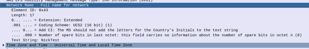
The major problem here is that there still won’t be an easy way to identify the operator of a particular network; the SPN is local only to the SIM and the Network Name is only present in the NAS messaging on an attach, and only after authentication.
If you’ve got a problem network, there’s no easy way to identify who’s operating it.
But as eSIMs become more prevalent and BIP / RFM on SIMs will hopefully allow operators to shift PLMNs without too much headache.
Ok, admittedly I haven’t actually seen “When a Stranger Calls”, or the less popular sequel “When a stranger Redials” (Ok may have made the last one up).
But the premise (as I read Wikipedia) is that the babysitter gets the call on the landline, and the police trace the call as originating from the landline.
But you can’t phone yourself, that’s not how local loops work – When the murderer goes off hook it loops the circuit, which busys it. You could apply ring current to the line I guess externally but unless our murder has a Ring generator or has setup a PBX inside the house, the call probably isn’t coming from inside the house.
On Topic – The GMLC
The GMLC (Gateway Mobile Location Centre) is a central server that’s used to locate subscribers within the network on different RATs (GSM/UMTS/LTE/NR).
The GMLC typically has interfaces to each of the radio access technologies, there is a link between the GMLC and the CS network elements (used for GSM/UMTS) such as the HLR, MSC & SGSN via Lh & Lg interfaces, and a link to the PS network elements (LTE/NR) via Diameter based SLh and SLg interfaces with the MME and HSS.
The GMLC’s tentacles run out to each of these network elements so it can query them as to a subscriber’s location,
LTE Call Flow
To find a subscriber’s location in LTE Diameter based signaling is used, to query the MME which in turn queries, the eNodeB to find the location.
But which MME to query?
The SLh Diameter interface is used to query the HSS to find out which MME is serving a particular Subscriber (identified by IMSI or MSISDN).
The LCS-Routing-Info-Request is sent by the GMLC to the HSS with the subscriber identifier, and the LCS-Routing-Info-Response is returned by the HSS to the GMLC with the details of the MME serving the subscriber.
Now we’ve got the serving MME, we can use the SLgDiameter interface to query the MME to the location of that particular subscriber.
The MME can report locations to the GMLC periodically, or the GMLC can request the MME provide a location at that point. For the GMLC to request a subscriber’s current location a Provide-Location-Request is set by the GMLC to the MME with the subscriber’s IMSI, and the MME responds after querying the eNodeB and optionally the UE, with the location info in the Provide-Location-Response.
(I’m in the process of adding support for these interfaces to PyHSS and all going well will release some software shortly to act at a GMLC so people can use this.)
Finding the actual Location
There are a few different ways the actual location of the UE is determined,
At the most basic level, Cell Global Identity (CGI) gives the identity of the eNodeB serving a user. If you’ve got a 3 sector site each sector typically has its own Cell Global Identity, so you can determine to a certain extent, with the known radiation pattern, bearing and location of the sector, in which direction a subscriber is. This happens on the network side and doesn’t require any input from the UE. But if we query the UE’s signal strength, this can then be combined with existing RF models and the signal strength reported by the UE to further pinpoint the user with a bit more accuracy. (Uplink and downlink cell coverage based positioning methods) Barometric pressure and humidity can also be reported by the base station as these factors will impact resulting signal strengths.
Timing Advance (TA) and Time of Arrival (TOA) both rely on timing signals to/from a UE to determine it’s distance from the eNodeB. If the UE is only served by a single cell this gives you a distance from the cell and potentially an angle inside which the subscriber is. This becomes far more useful with 3 or more eNodeBs in working range of the UE, where you can “triangulate” the UE’s location. This part happens on the network side with no interaction with the UE. If the UE supports it, EUTRAN can uses Enhanced Observed Time Difference (E-OTD) positioning method, which does TOD calcuation does this in conjunction with the UE.
GPS Assisted (A-GPS) positioning gives good accuracy but requires the devices to get it’s current location using the GPS, which isn’t part of the baseband typically, so isn’t commonly implimented.
Uplink Time Difference of Arrival (UTDOA) can also be used, which is done by the network.
So why do we need to get Subscriber Locations?
The first (and most noble) use case that springs to mind is finding the location of a subscriber making a call to emergency services. Often upon calling an emergency services number the GMLC is triggered to get the subscriber’s location in case the call is cut off, battery dies, etc.
But GMLCs can also be used for lots of other purposes, marketing purposes (track a user’s location and send targeted ads), surveillance (track movements of people) and network analytics (look at subscriber movement / behavior in a specific area for capacity planning).
Different countries have different laws regulating access to the subscriber location functions.
Hack to disable Location Reporting on Mobile Networks
If you’re wondering how you can disable this functionality, you can try the below hack to ensure that your phone does not report your location.
Press the power button on your phone
Turn it off
In reality, no magic super stealth SIM cards, special phones or fancy firmware will prevent the GMLC from finding your location. So far none of the “privacy” products I’ve looked at have actually done anything special at the Baseband level. Most are just snakeoil.
For as long as your device is connected to the network, the passive ways of determining location, such as Uplink Time Difference of Arrival (UTDOA) and the CGI are going to report your location.
I never cease to be amazed as to what I can do with Wireshark.
While we’re working with Smart Card readers and SIM cards, capturing and Decoding USB traffic to see what APDUs are actually being sent can be super useful, so in this post we’ll look at how we can use Wireshark to sniff the USB traffic to view APDUs being sent to smart cards from other software.
For the purposes of this post I’ll be reading the SIM cards with pySim, but in reality it’ll work with any proprietary SIM software, allowing you to see what’s actually being said to the card by your computer.
If you want to see what’s being sent between your phone and SIM card, the Osmocom SIMtrace is the device for you (And yes it also uses Wireshark for viewing this data!).
Ok, that’s all the prerequisites sorted, next we need to find the bus and device ID of our smart card reader,
We can get this listed with
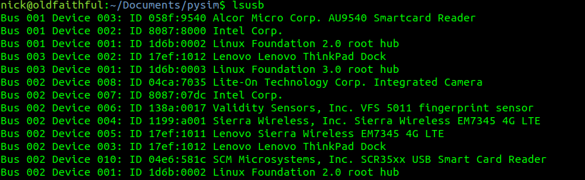
lsusb
Here you can see I have a Smart Card reader on Bus 1 device 03 and another on Bus 2 device 10.
The reader I want to use is the “SCM Microsystems, Inc. SCR35xx USB Smart Card Reader” so I’ll jott down Bus 2 device 10. Yours will obviously be different, but you get the idea.
Finding the USB traffic in Wireshark
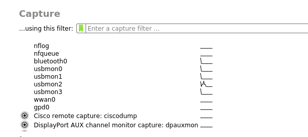
Next we’ll fire up Wireshark, if you’ve got your permissions right and followed along, you should see a few more interfaces starting with usbmonX in the capture list.
Because the device I want to capture from is on Bus 2, we’ll select usbmon2 and start capturing,
As you can see we’ve got a bit of a firehose of data, and we only care about device 10 on bus 2, so let’s filter for that.
So let’s generate some data and then filter for it, to generate some data I’m going to run pySim-read to read the data on a smart card that’s connected to my PC, and then filter to only see traffic on that USB device,
In my case as the USB device is 10 it’s got two sub addresses, so I’ll filter for USB Bus 2, device 10 sub-address 1 and 2, so the filter I’ll use is:
usb.addr=="2.10.1" or usb.addr=="2.10.2"
But this doesn’t really show us much, so let’s tell Wireshark this is PCSC/UCCID data to decode it as such;
So we’ll select some of this traffic -> Decode as -> USBCCID
Still not seeing straight APDUs, so let’s tell Wireshark one more bit of information – That we want to decode this information as GSM SIM data;
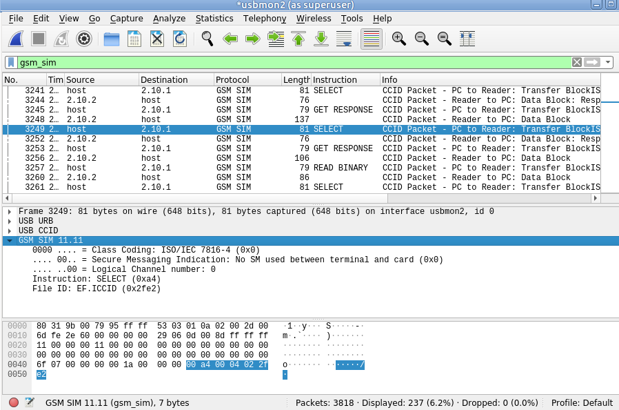
Again, we’ll select the data part of the USBCCID traffic -> Decode As -> GSM_SIM
And bingo, just like that we can now filter by gsm_sim and see the APDUs being sent / received.
While we’ve already covered the inputs required by the authentication elements of the core network (The HSS in LTE/4G, the AuC in UMTS/3G and the AUSF in 5G) to generate an output, it’s worth noting that the Confidentiality Algorithms used in the process determines the output.
This means the Authentication Vector (Also known as an F1 and F1*) generated for a subscriber using Milenage Confidentiality Algorithms will generate a different output to that of Confidentiality Algorithms XOR or Comp128.
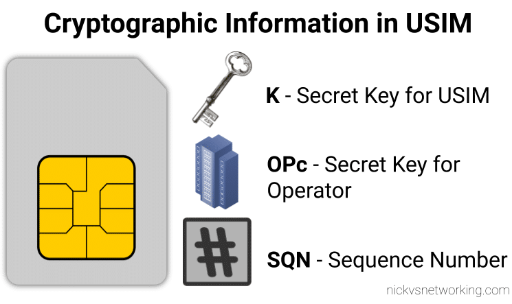
To put it another way – given the same input of K key, OPc Key (or OP key), SQN & RAND (Random) a run with Milenage (F1 and F1* algorithm) would yield totally different result (AUTN & XRES) to the same inputs run with a simple XOR.
Technically, as operators control the network element that generates the challenges, and the USIM that responds to them, it is an option for an operator to implement their own Confidentiality Algorithms (Beyond just Milenage or XOR) so long as it produced the same number of outputs. But rolling your own cryptographic anything is almost always a terrible idea.
So what are the differences between the Confidentiality Algorithms and which one to use? Spoiler alert, the answer is Milenage.
Milenage
Milenage is based on AES (Originally called Rijndael) and is (compared to a lot of other crypto implimentations) fairly easy to understand,
AES is very well studied and understood and unlike Comp128 variants, is open for anyone to study/analyse/break, although AES is not without shortcomings, it’s problems are at this stage, fairly well understood and mitigated.
There are a few clean open source examples of Milenage implementations, such as this C example from FreeBSD.
XOR
It took me a while to find the specifications for the XOR algorithm – it turns out XOR is available as an alternate to Milenage available on some SIM cards for testing only, and the mechanism for XOR Confidentiality Algorithm is only employed in testing scenarios, not designed for production.
Instead of using AES under the hood like Milenage, it’s just plan old XOR of the keys.
Comp128 was originally a closed source algorithm, with the maths behind it not publicly available to scrutinise. It is used in GSM A3 and A5 functions, akin to the F1 and F1* in later releases.
Due to its secretive nature it wasn’t able to be studied or analysed prior to deployment, with the idea that if you never said how your crypto worked no one would be able to break it. Spoiler alert; public weaknesses became exposed as far back as 1998, which led to Toll Fraud, SIM cloning and eventually the development of two additional variants, with the original Comp128 renamed Comp128-1, and Comp128-2 (stronger algorithm than the original addressing a few of its flaws) and Comp128-3 (Same as Comp128-2 but with a 64 bit long key generated).
In our last post we covered the file system structure of a smart card and the basic concepts of communication with cards. In this post we’ll look at what happens on the application layer, and how to interact with a card.
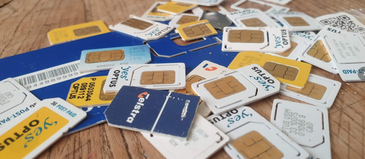
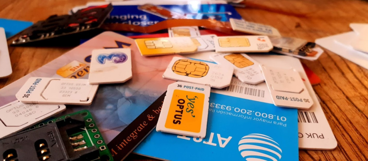
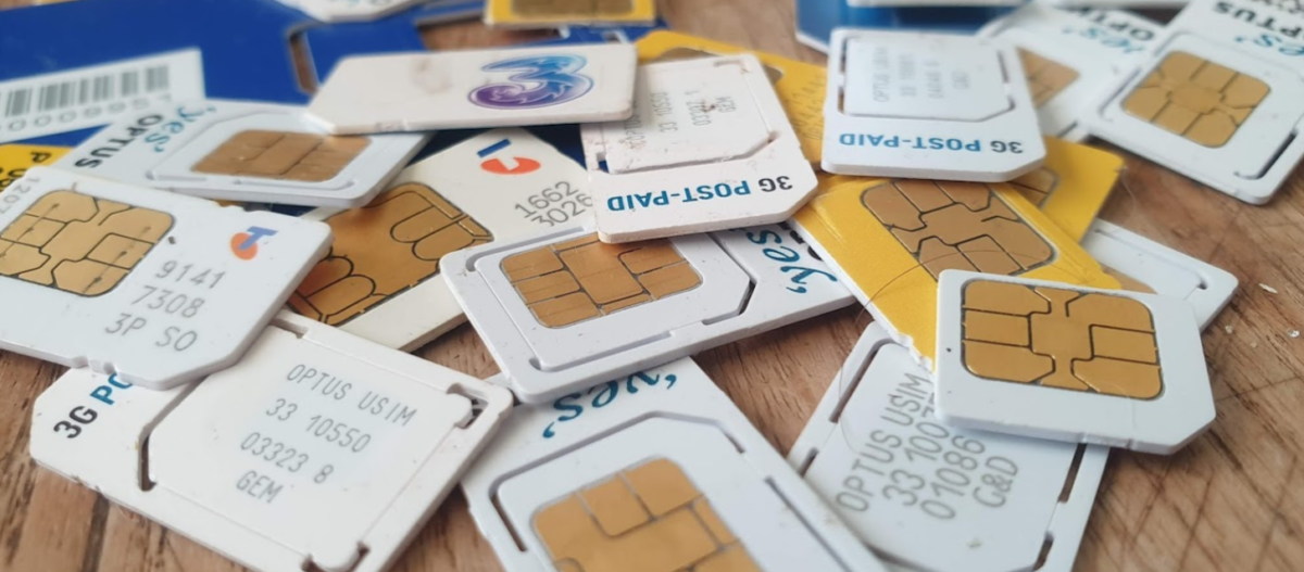
For these examples I’ll be using SIM cards, because admit it, you’ve already got a pile sitting in a draw, and this is a telco blog after all. You won’t need the ADM keys for the cards, we’ll modify files we’ve got write access to by default.
Commands & Instructions
So to do anything useful with the card we need issue commands / instructions to the card, to tell it to do things. Instructions like select this file, read it’s contents, update the contents to something else, verify my PIN, authenticate to the network, etc.
The term Command and Instruction are used somewhat interchangeably in the spec, I realise that I’ve done the same here to make it just as confusing, but instruction means the name of the specific command to be called, and command typically means the APDU as a whole.
The “Generic Commands” section of 3GPP TS 31.101 specifies the common commands, so let’s take a look at one.
The creatively named SELECT command/instruction is used to select the file we want to work with. In the SELECT command we’ll include some parameters, like where to find the file, so some parameters are passed with the SELECT Instruction to limit the file selection to a specific area, etc, the length of the file identifier to come, and the identifier of the file.
The card responds with a Status Word, returned by the card, to indicate if it was successful. For example if we selected a file that existed and we had permission to select, we’d get back a status word indicating the card had successfully selected the file. Status Words are 2 byte responses that indicate if the instruction was successful, but also the card has data it wants to send to the terminal as a result of the instruction, how much data the terminal should expect.
So if we just run a SELECT command, telling the card to select a file, we’ll get back a successful response from the card with a data length. Next need to get that data from the card. As the card can’t initiate communication, the GET RESPONSE instruction is sent to the card to get the data from the card, along with the length of the data to be returned.
The GET RESPONSE instruction/command is answered by the card with an APDU containing the data the card has to send, and the last 2 bytes contain the Status Word indicating if it was successful or not.
APDUs
So having covered the physical and link layers, we now move onto the Application Layer – where the magic happens.
Smart card communications is strictly master-slave based when it comes to the application layer.
The terminal sends a command to the card, which in turn sends back a response. Command -> Response, Command -> Response, over and over.
These commands are contained inside APplication Data Units (APDUs).
So let’s break down a simple APDU as it appears on the wire, so to speak.
The first byte of our command APDU is taken up with a header called the class byte, abbreviated to CLA. This specifies class coding, secure messaging options and channel options.
In the next byte we specify the Instruction for the command, that’s the task / operation we want the card to perform, in the spec this is abbreviated to INS.
The next two bytes, called P1 & P2 (Parameter 1 & Parameter 2) specify the parameters of how the instruction is to be to be used.
Next comes Lc – Length of Command, which specifies the length of the command data to follow,
Datacomes next, this is instruction data of the length specified in Lc.
Finally an optional Le – Length of expected response can be added to specify how long the response from the card should be.
Crafting APDUs
So let’s encode our own APDU to send to a card, for this example we’ll create the APDU to tell the card to select the Master File (MF) – akin to moving to the root directory on a *nix OS.
For this we’ll want a copy of ETSI TS 102 221 – the catchily named “Smart cards; UICC-Terminal interface; Physical and logical characteristics” which will guide in the specifics of how to format the command, because all the commands are encoded in hexadecimal format.
So here’s the coding for a SELECT command from section 11.1.1.1 “SELECT“,
For the CLA byte in our example we’ll indicate in our header that we’re using ISO 7816-4 encoding, with nothing fancy, which is denoted by the byte A0.
For the next but we’ve got INS (Instruction) which needs to be set to the hex value for SELECT, which is represented by the hex value A4, so our second byte will have that as it’s value.
The next byte is P1, which specifies “Selection Control”, the table in the specification outlines all the possible options, but we’ll use 00 as our value, meaning we’ll “Select DF, EF or MF by file id”.
The next byte P2 specifies more selection options, we’ll use “First or only occurrence” which is represented by 00.
The Lc byte defines the length of the data (file id) we’re going to give in the subsequent bytes, we’ve got a two byte File ID so we’ll specify 2 (represented by 02).
Finally we have the Data field, where we specify the file ID we want to select, for the example we’ll select the Master File (MF) which has the file ID ‘3F00‘, so that’s the hex value we’ll use.
So let’s break this down;
Code
Meaning
Value
CLA
Class bytes – Coding options
A0 (ISO 7816-4 coding)
INS
Instruction (Command) to be called
A4 (SELECT)
P1
Parameter 1 – Selection Control (Limit search options)
00 (Select by File ID)
P2
Parameter 1 – More selection options
00 (First occurrence)
Lc
Length of Data
02 (2 bytes of data to come)
Data
File ID of the file to Select
3F00 (File ID of master file)
So that’s our APDU encoded, it’s final value will be A0 A4 00 00 02 3F00
So there we have it, a valid APDU to select the Master File.
In the next post we’ll put all this theory into practice and start interacting with a real life SIM cards using PySIM, and take a look at the APDUs with Wireshark.
The pins on the terminal / card reader are arranged so that when inserting a card, the ground contact is the first contact made with the reader, this clever design consideration to protect the card and the reader from ESD damage.
Operating Voltages
When Smart Cards were selected for use in GSM for authenticating subscribers, all smart cards operated at 5v. However as mobile phones got smaller, the operating voltage range became more limited, the amount of space inside the handset became a premium and power efficiency became imperative. The 5v supply for the SIM became a difficult voltage to provide (needing to be buck-boosted) so lower 3v operation of the cards became a requirement, these cards are referred to as “Class B” cards. This has since been pushed even further to 1.8v for “Class C” cards.
If you found a SIM from 1990 it’s not going to operate in a 1.8v phone, but it’s not going to damage the phone or the card.
The same luckily goes in reverse, a card designed for 1.8v put into a phone from 1990 will work just fine at 5v.
This is thanks to the class flag in the ATR response, which we’ll cover later on.
Clocks
As we’re sharing one I/O pin for TX and RX, clocking is important for synchronising the card and the reader. But when smart cards were initially designed the clock pin on the card also served as the clock for the micro controller it contained, as stable oscillators weren’t available in such a tiny form factor. Modern cards implement their own clock, but the clock pin is still required for synchronising the communication.
I/O Pin
The I/O pin is used for TX & RX between the terminal/phone/card reader and the Smart Card / SIM card. Having only one pin means the communications is half duplex – with the Terminal then the card taking it in turns to transmit.
Reset Pin
Resets the card’s communications with the terminal.
Filesystem
So a single smart card can run multiple applications, the “SIM” is just an application, as is USIM, ISIM and any other applications on the card.
These applications are arranged on a quasi-filesystem, with 3 types of files which can be created, read updated or deleted. (If authorised by the card.)
Because the file system is very basic, and somewhat handled like a block of contiguous storage, you often can’t expand a file – when it is created the required number of bytes are allocated to it, and no more can be added, and if you add file A, B and C, and delete file B, the space of file B won’t be available to be used until file C is deleted.
This is why if you cast your mind back to when contacts were stored on your phone’s SIM card, you could only have a finite number of contacts – because that space on the card had been allocated for contacts, and additional space can no longer be allocated for extra contacts.
So let’s take a look at our 3 file types:
MF (Master File)
The MF is like the root directory in Linux, under it contains all the files on the card.
DF (Dedciated File)
An dedicated file (DF) is essentially a folder – they’re sometimes (incorrectly) referred to as Directory Files (which would be a better name).
They contain one or more Elementary Files (see below), and can contain other DFs as well.
Dedicated Files make organising the file system cleaner and easier. DFs group all the relevant EFs together. 3GPP defines a dedicated file for Phonebook entries (DFphonebook), MBMS functions (DFtv) and 5G functions (DF5gs).
We also have ADFs – Application Dedicated Files, for specific applications, for example ADFusim contains all the EFs and DFs for USIM functionality, while ADFgsm contains all the GSM SIM functionality.
The actual difference with an ADF is that it’s not sitting below the MF, but for the level of depth we’re going into it doesn’t matter.
DFs have a name – an Application Identifier (AID) used to address them, meaning we can select them by name.
EF (Elementary File)
Elementary files are what would actually be considered a file in Linux systems.
Like in a Linux file systems EFs can have permissions, some EFs can be read by anyone, others have access control restrictions in place to limit who & what can access the contents of an EF.
There are multiple types of Elementary Files; Linear, Cyclic, Purse, Transparent and SIM files, each with their own treatment by the OS and terminal.
Most of the EFs we’ll deal with will be Transparent, meaning they ##
ATR – Answer to Reset
So before we can go about working with all our files we’ll need a mechanism so the card, and the terminal, can exchange capabilities.
There’s an old saying that the best thing about standards is that there’s so many to choose, from and yes, we’ve got multiple variants/implementations of the smart card standard, and so the card and the terminal need to agree on a standard to use before we can do anything.
This is handled in a process called Answer to Reset (ATR).
When the card is powered up, it sends it’s first suggestion for a standard to communicate over, if the terminal doesn’t want to support that, it just sends a pulse down the reset line, the card resets and comes back with a new offer.
If the card offers a standard to communicate over that the terminal does like, and does support, the terminal will send the first command to the card via the I/O line, this tells the card the protocol preferences of the terminal, and the card responds with it’s protocol preferences. After that communications can start.
Basic Principles of Smart Cards Communications
So with a single I/O line to the card, it kind of goes without saying the communications with the card is half-duplex – The card and the terminal can’t both communicate at the same time.
Instead a master-slave relationship is setup, where the smart card is sent a command and sends back a response. Command messages have a clear ending so the card knows when it can send it’s response and away we go.
Like most protocols, smart card communications is layered.
At layer 1, we have the physical layer, defining the operating voltages, encoding, etc. This is standardised in ISO/IEC 7816-3.
Above that comes our layer 2 – our Link Layer. This is also specified in ISO/IEC 7816-3, and typically operates in one of two modes – T0 or T1, with the difference between the two being one is byte-oriented the other block-oriented. For telco applications T0 is typically used.
Our top layer (layer 7) is the application layer. We’ll cover the details of this in the next post, but it carries application data units to and from the card in the form of commands from the terminal, and responses from the card.
Coming up Next…
In the next post we’ll look into application layer communications with cards, the commands and the responses.
I know a little bit about SIM cards / USIM cards / ISIM Cards. Enough to know I don’t know very much about them at all.
So throughout this series of posts of unknown length, I’ll try and learn more and share what I’m learning, citing references as much as possible.
So where to begin? I guess at the start,
A supposedly brief history of Smart Cards
There are two main industries that have driven the development and evolution of smart cards – telecom & banking / finance, both initially focused on the idea that carrying cash around is unseemly.
This planet has – or rather had – a problem, which was this: most of the people living on it were unhappy for pretty much of the time. Many solutions were suggested for this problem, but most of these were largely concerned with the movement of small green pieces of paper, which was odd because on the whole it wasn’t the small green pieces of paper that were unhappy.
Douglas Adams – The Hitchhiker’s Guide to the Galaxy
When the idea of Credit / Debit Cards were first introduced the tech was not electronic, embossed letters on the card were fed through that clicky-clacky-transfer machine (Google tells me this was actually called the “credit card imprinter”) and the card details imprinted onto carbon copy paper.
Customers wanted something faster, so banks delivered magnetic strip cards, where the card data could be read even more quickly, but as the security conscious of you will be aware, storing data on magnetic strips on a card to be read by any reader, allows them to be read by any reader, and therefore duplicated really easily, something the banks quickly realised.
To combat this, card readers typically would have a way to communicate back to a central bank computer. The central computer verified the PIN entered by the customer was correct, confirmed that the customer had enough money in their balance for the transaction and it wasn’t too suspicious. This was, as you would imagine in the late 1980’s early 1990’s, rather difficult to achieve. A reliable (and cheap) connection back to a central bank computer wasn’t always a given, nor instant, and so this was still very much open to misuse.
“Carders” emmerged, buying/selling/capturing credit card details, and after programming a blank card with someone else’s fraudulently obtained card details, could write them on a blank card before going on a spending spree for a brief period of time. Racking up a giant debt that wasn’t reconciled against the central computer until later, when the card was thrown away and replaced with another.
I know what you’re thinking – I come to this blog for ramblings about Telecommunications, not the history of the banking sector. So let’s get onto telco;
The telecom sector faced similar issues, at the time mobile phones were in their infancy, and so Payphones were how people made calls when out and about.
A phone call from a payphone in Australia has sat at about $0.40 for a long time, not a huge amount, but enough you’d always want to be carrying some change if you wanted to make calls. Again, an inconvenience for customers as coins are clunky, and an inconvenience for operators as collecting the coins from tens of thousands of payphones is expensive.
Telcos around the world trailed solutions, including cards with magnetic strips containing the balance of the card, but again people quickly realised that you could record the contents of the magnetic stripe data of the card when it had a full balance, use all the balance on the card, and then write back the data you stored earlier with a full balance.
So two industries each facing the same issue: it’s hard to securely process payments offline in a way that can’t be abused.
Enter the smart card – a tiny computer in a card that the terminal (Payphone or Credit Card Reader) interacts with, but the card is very much in charge.
When used in a payphone, the caller inserts the smart card and dials the number, and dialog goes something like this (We’ll assume Meter Pulses are 40c worth):
Payphone: “Hey SmartCard, how much credit do you have on you?”
Smart Card: “I have $1.60 balance”
*Payphone ensures card has enough credit for the first meter pulse, and begins listening for Meter Pulses*
*When a meter pulse received:*
Payphone: “Please deduct $0.40 from your Balance”
Smart Card: “Ok, you have $1.20 remaining”
This process repeats for each meter pulse (Payphone metering is a discussion for another day) until all the credit has been used / Balance is less than 1 meter pulse charge.
While anyone could ask the smart card “Hey SmartCard, how much credit do you have on you?” it would only return the balance, and if you told the smart card “I used $1 credit, please deduct it” like the payphone did, you’d just take a dollar off the credit stored on the card.
Saying “Hey SmartCard set the balance to $1,000,000” would result in a raised eyebrow from the SmartCard who rejects the request.
After all – It’s a smart card. It has the capability to do that.
So in the telecom sector single use smart cards were rolled out, programmed in the factory with a set dollar value of credit, sold at that dollar value and thrown away when depleted.
The banking industry saw even more potential, balance could be stored on the card, and the PIN could be verified by the card, the user needs to know the correct PIN, as does the smart card, but the terminal doesn’t need to know this, nor does it need to talk back to a central bank computer all the time, just every so often so the user gets the bill.
It worked much the same way, although before allowing a deduction to be made from the balance of the card, a user would have to enter their PIN which was verified by the card before allowing the transaction.
Eventually these worlds collided (sort of), both wanting much the same thing from smart cards. So the physical characteristics, interface specs (rough ones) and basic communications protocol was agreed on, and what eventually became ISO/IEC 7816 was settled upon.
Any card could be read by any terminal, and it was up to the systems implementer (banks and telecos initially) what data the card did and what the terminal did.
Active RFID entered the scene and there wasn’t even a need for a physical connection to the card, but the interaction was the same. We won’t really touch on the RFID side, but all of this goes for most active RFID cards too.
Enter Software
Now the card was a defined standard all that was important really was the software on the card. Banks installed bank card software on their cards, while telcos installed payphone card software on theirs.
But soon other uses emerged, ID cards could provide a verifiable and (reasonably) secure way to verify the card’s legitimacy, public transport systems could store commuter’s fares on the card, and vending machines, time card clocks & medical records could all jump on the bandwagon.
These were all just software built on the smart card platform.
Hello SIM Cards
A early version Smart card was used in the German C-Netz cellular network, which worked in “mobile” phones and also payphones, to authenticate subscribers.
After that the first SIM cards came into the public sphere in 1991 with GSM as a way to allow a subscriber’s subscription to be portable between devices, and this was standardised by ETSI to become the SIM cards still used in networks using GSM, and evolved into the USIM used in 3G/4G/5G networks.
Names of Smart Cards & Readers
To make life a bit easier I thought I’d collate all the names for smart cards and readers that are kind of different but used interchangeably depending on the context.
Smart Card
|
Terminal
UICC (Universal Integrated Circuit Card) – Standards name for Smart Card
Card Reader (Generic)
SIM (Mobile Telco application running on UICC)
Phone (Telco)
USIM (Mobile Telco application running on UICC)
SIM Slot (Telco)
Credit / Debit / EFTPOS Card (Banking)
UE (Telco)
Java Card (Type of Smart Card OS)
EFTPOS Terminal (Banking)
Phone Card (Telco / Payphone)
And then…
From here we’ll look at various topics:
Introduction to Smart Cards (This post)
Meet & Greet (The basics of Smart Cards & their File System)
APDUs and Hello Card (How terminals interact with a smart cards)
(Interacting with real life cards using Smart Card readers and SIM cards)
Mixing It Up (Changing values on Cards)
Other topics we may cover are Javacard and Global Platform, creating your own smart card applications, a deeper look at the different Telco apps like SIM/USIM/ISIM, OTA Updates for cards / Remote File Management (RFM), and developing for SimToolkit.
The SUPI (Subscription Permanent Identifier) replaces the IMSI as the unique identifier for each Subscriber in 5G.
One of the issues with using IMSI in LTE/EUTRAN is there were a few occasions where the IMSI was sent over the clear – meaning the IMSIs of subscribers nearby could be revealed to anyone listening.
So what is a SUPI and what does it look like? Well, most likely it’ll look like an IMSI – 15 or 16 digits long, with the MCC/MNC as the prefix.
If you’re using a non-3GPP RAT it could be a RFC 4282 Network Access Identifier, but if it’s on a SIM card or in a Mobile Device, it’s probably exactly the same as the IMSI.
SUCI Subscription Concealed Identifier
Our SUPI is never sent over the air in the clear / plaintext, instead we rely on the SUCI (Subscription Concealed Identifier) for this, which replaces the GUTI/TMSI/IMSI for all plaintext transactions over the air.
Either the UE or the SIM generate the SUCI (if it’s done by the SIM it’s much slower), based on a set of parameters defined on the SIM.
The SUCI has to be generated by the UE or SIM in a way the Network can identify the SUPI behind the SUCI, but no one else can.
In LTE/EUTRAN this was done by the network randomly assigning a value (T-MSI / GUTI) and the network keeping track of which randomly assigned value mapped to which user, but initial attach and certain handovers revealed the real IMSI in the clear, so for 5G this isn’t an option.
So let’s take a look at how SUCI is calculated in a way that only the network can reveal the SUPI belonging to a SUCI.
The Crypto behind SUCI Calculation
As we’ll see further down, SUCI is actually made up of several values concatenated together. The most complicated of these values is the Protection Scheme Output, the cryptographically generated part of the SUCI that can be used to determine the SUPI by the network.
Currently 3GPP defines 3 “Protection Scheme Profiles” for calculating the SUCI.
Protection Scheme Identifier 1 – null-scheme
Does nothing. Doesn’t conceal the SUPI at all. If this scheme is used then the Protection Scheme Output is going to just be the SUPI, for anyone to sniff off the air.
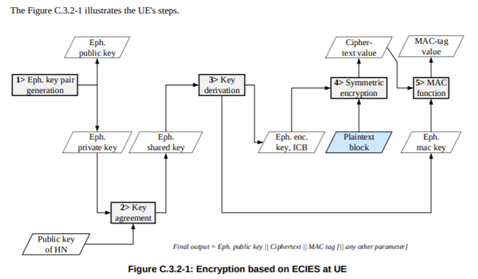
Protection Scheme Identifier 2 & 3 – ECIES scheme profile A & B
The other two Protection Scheme Identifiers both rely on Elliptic Curve Integrated Encryption Scheme (ECIES) for generation.
So if both Profile A & Profile B rely on Elliptic Curve Integrated Encryption Scheme, then what’s the difference between the two?
Well dear reader, the answer is semantics! There’s lots of parameters and variables that go into generating a resulting value from a cryptographic function, and Profile A & Profile B are just different parameters being used to generate the results.
For crypto nerds you can find the specifics in C.3.4.1 Profile A and C.3.4.1 Profile B outlined in 3GPP TS 33.501.
For non crypto nerds we just need to know this;
When the SIM is generating the SUCI the UE just asks for an identity by executing the GET IDENTITY command ADF against the SIM and uses the response as the SUCI.
When the UE is generating the SUCI, the UE gets the SUCI_Calc_Info EF contents from the SIM and extracts the Home Network Public Key from it’s reply. It uses this Home Network Public Key and a freshly created ephemeral public/private key pair to generate a SUCI value to use.
Creating the SUCI
After generating a Protection Scheme Output, we’ll need to add some extra info into it to make it useful.
The first digit of the SUCI is the SUPI type, a value of 0 denotes the value contained in the Protection Scheme Output is an IMSI, while 1 is used for Network Access Indicator for Non 3GPP access.
Next up we have the Home Network Identifier, which in a mobile environment is our PLMN (MCC/MCC).
Then a Routing Indicator, 1-4 digits long, is used with the Home Network Identifier to route the Authentication traffic to the UDM that contains that subscriber’s information, ie you may have MVNOs with their own UDM. If the routing indicator of 10 is assigned to the MVNOs SIMs then the AMF can be set to route traffic with a routing indicator of 10 to the UDM of the VMNO.
The Protection Scheme we covered earlier, with the 3 types of protection scheme (Null & two relying on Elliptic Curve Integrated Encryption Scheme).
Home Network Public Key Identifier identifies which Public Key was used to generate the Protection Scheme Output.
Finally we have the Protection Scheme Output which we covered generating in the previous session.
Usage in Signaling
The SUPI is actually rarely used beyond the initial attach to the network.
After authenticating to the network using AKA and the SUCI, in 5GC, like in LTE/EUTRAN, a shorter GUTI is used which further protects the subscriber’s identity and changes frequently.
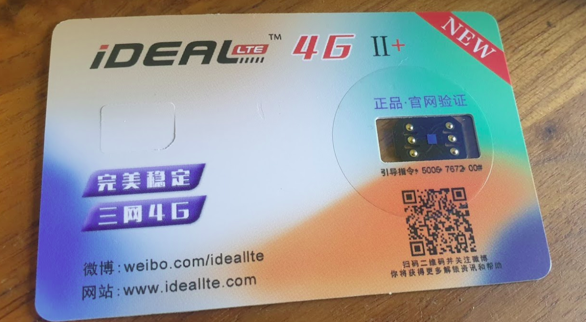
There’s a lot of “Magic Unlock SIM” products online; IdeaLTE, U-SIM LTE 4G Pro II (sic), UltraSIM, TurboSIM etc, with no real description as to what they are or how they work,
They claim to do something to do with unlocking iPhones, but with little other info.
Being interested in SIM technology, and with no real idea what they are I ordered a few.
What are they?
They’re man-in-the-middle SIM card devices that are able to intercept requests from the UE / baseband of the device.
They sit on top of the real SIM card, between it and the SIM Slot.
One of the ones I bought had a sticker on it that helped stick it into place, the other just sat above the SIM below the phone.
This means when the UE sends the APDU to request some data from the card, the SIM-shim device analyses the request, and if it matches the rules on the SIM-Shim, intercepts it and responds with something else, ignoring the data the real SIM card would send back and injecting its own,
The use for this seems to be to do with how Apple does Carrier Locking on the iPhone. It seems in the iPhone carrier settings are ranges of ICCIDs used by the different carriers for their SIMs, and uses that to identify the carrier of the SIM.
With this information it’s able to determine if the SIM card is from the carrier the iPhone is locked to or not,
Now you’re probably seeing the value in this attack – By intercepting the request for the ICCID of the card, and instead of responding with the real ICCID, the SIM-Shim intercepts the request and sending back an ICCID of a card the iPhone is carrier locked to, the iPhone is tricked into thinking it’s talking to a card from the carrier the phone is locked to.
So let’s say we’ve got an iPhone from Carrier A, and they’ve told Apple their SIM cards have ICCIDs in the range from 0001 to 0005, If I put a SIM card with the ICCID 0003 the iPhone knows it’s a SIM from Carrier A, If I put in a SIM card with ICCID 9999 the iPhone knows the SIM is not from carrier A, and therefore prevents me from using the iPhone, But if I put in one of these SIM Shims, when the iPhone ask the ICCID of the card, the SIM Shim will respond with an ICCID we set on it, so if we want to use SIM with ICCID 9999 in a phone locked to Carrier A, all we’ve got to do is setup the SIM-Shim to respond with ICCID of 0001 for example.
Phew. Ok, that’s the short run down on how it works (There’s more to activating iPhones but we’re here to talk about SIMs!).
The Hardware
So physically these are “shims” – they sit between the real SIM and the mobile phone and intercept the communications.
It blows my mind that someone’s been able to manufacture these in such a small form factor.
But there is one rather glaring flaw in having a tiny wafer that sits on top of your regular SIM, and that is if it pops up/down/ get loose and become hellish to get out.
I found their insertion and removal is a bit of a game of Russian roulette as to if it will go in, or come out, without brute force and potential damage to the device.
In the end on one iPhone I had to force the SIM tray out with a set of needle nose pliers, and my little SIM-shim was pretty beaten up and no longer useable. RIP SIM-Shim 1.
I think this may have been an early version of the same thing? Or possibly to allow dual SIM on an iPhone?
The Software
Interacting with the IdealLTE for example, is via SIM Toolkit Application for managing ICCIDs.
You can set any ICCID you want, which is cool, but limited.
Unfortunately I haven’t been able to find any way of messing with these to allow interception / replacement for other APDUs, for example if you could change the Administrative Domain to get higher access to the network.
I will at some stage put these into a SIMtrace and compare the output, and have a poke around and see if I can find anyway to change / update these, or if there’s any APDUs it responds interestingly to.
Unfortunately I’ve actually lost the new unit I had to replace the one I broke, they are very very small…
I reached out to the developer / vendor but they seem to go dark and popup under a different name, I’m not holding my breath…
Oftentimes I’m developing something locally and I need an SSL Certificate.
I’m too cheap to buy a valid SSL cert for a subdomain like “dev.nickvsnetworking.com” and often the domain changes based on what I’m doing,
LetsEncrypt is great, but requires your server to be public facing and be a web server, which for dev stuff isn’t really practical,
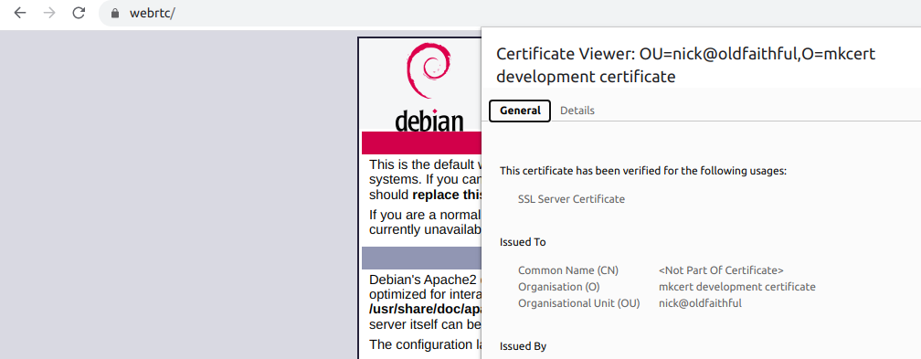
Enter mkcert – a tool that allows you to generate valid SSL certificates on your machine for any domain, the catch is that it’s only on your machine.
I’m working on a WebSocket platform at the moment, which requires an SSL certificate.
So I set an entry in my hosts file to point “webrtc” to the IP of one of the machines,
I then generated the cert on my local machine,
mkcert -install webrtc
Which outputs the certificate and private key, which I copied it onto the server I’m working on, twiddled some knobs in Apache2 and presto, valid cert!
The downside is of course anyone else going to this site would see the cert as invalid, but as it’s just me, it doesn’t matter!
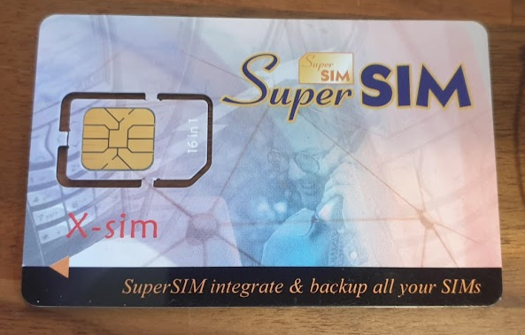
I found a “16-in-1 Super SIM X-SIM” in my SIM card drawer, I think I ordered these when I was first playing with GSM and never used it.
I was kind of curious about how these actually worked, so after some online sleuthing I found a very suspicious looking rar file, which I ended up running in a VM and mapping the Card Reader to the VM.
What a treat I was in for in terms of UI.
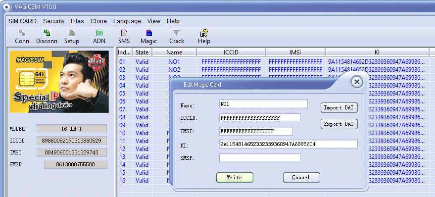
The concept is quite simple, you program a series of IMSI and K key values onto the SIM card, and then using a SIM Toolkit application, you’re able to select which IMSI / K key combination you want to use.
A neat trick, I’d love a LTE version of this for changing values on the fly, but it’d be a pretty niche item considering no operator is going to give our their K and OPc keys,
But come to think of it, no GSM operator would give out K keys, so how do you get the K key from your commercial operator?
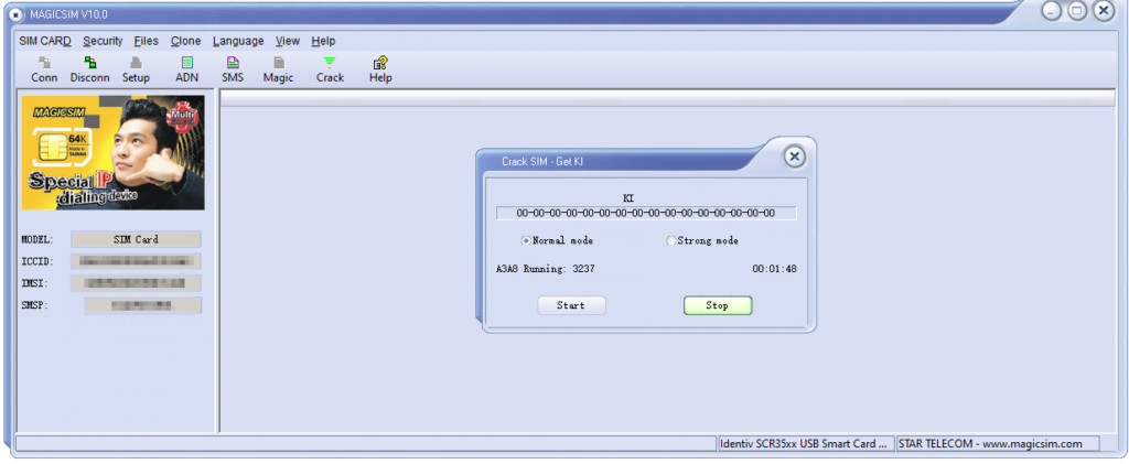
I noticed the grayed out “Crack” icon on the menu.
After rifling through my SIM drawer I found a few really old 2G SIMs, stuck one in, reconnected and clicked “Crack” and then start.
I left it running in the background after the manual suggested it could take up to 24 hours to run through all the codes.
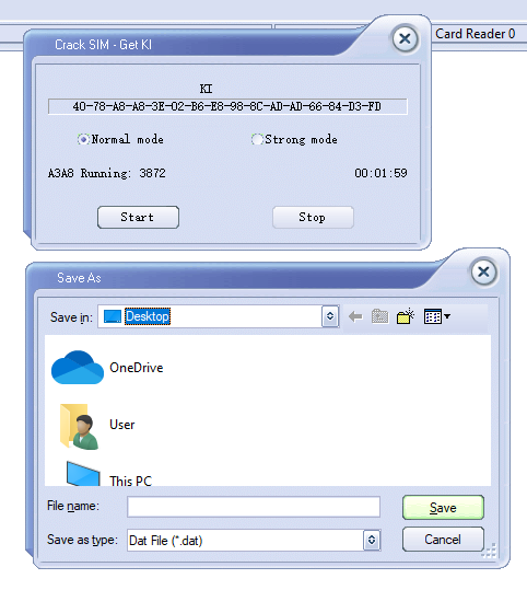
To my surprise after 2 minutes the software was requesting I save the exported data, which I did.
Then I put the 16 in 1 back in, selected Magic and then imported the cracked SIM data (IMSI, ICCID, Ki & SMSp).
By the looks of it the software is just running a brute force attack on the SIM card, and the keyspace is only so large meaning it can be reversed in.
I did a bit of research to find out if this is exploiting any clever vulnerabilities in UCCID cards, but after running some USB Pcap traces it looks like it’s just plain old brute force, which could be easily defended against by putting a pause between auth attempts on the SIM.
I’ve no idea if that’s the actual K value I extracted from the SIM – The operator that issued the SIM doesn’t even exist anymore, but I’ll add the details to the HLR of my Osmocom GSM lab and see if it matches up.
Out of curiosity I also connected some of my development USIM/ISIM/SIM cards that I can program, the software is amazing in it’s response:
It’s probably pretty evident to most why you’d want to use TLS these days,
SIP Secure – aka sips has been around for a long time and is supported by most SIP endpoints now.
Kamailio supports TLS, and it’s setup is very straightforward.
I’ve got a private key and certificate file for the domain nickvsnetworking.com so I’ll use those to secure my Kamailio instance by using TLS.
I’ll start by copying both the certificate (in my case it’s cert.pem) and the private key (privkey.pem) into the Kamailio directory. (If you’ve already got the private key and certificate on your server for another application – say a web server, you can just reference that location so long as the permissions are in place for Kamailio to access)
Next up I’ll open my Kamailio config (kamailio.cfg), I’ll be working with an existing config and just adding the TLS capabilities, so I’ll add this like to the config:
!define WITH_TLS
That’s pretty much the end of the configuration in kamailio.cfg, if we have a look at what’s in place we can see that the TLS module loads it’s parameters from a separate file;
After restarting Kamailio subscribers can now contact us via TLS using sips.
You may wish to disable TCP & UDP transport in favor of only TLS.
A note about CAs…
If you’re planning on rolling out SIP over TLS (sips) to existing IP phones it’s worth looking at what Certificate Authorities (CAs) are recognised by the IP phones.
As TLS relies on a trust model where a CA acts kind of like a guarantor to the validity of the certificate, if the IP phone doesn’t recognise the CA, it may see the certificate as Invalid.
Some IP phones for example won’t recognize Let’s Encrypt certificates as valid, while others may not recognize any of the newer CAs.
The Proxy-Call Session Control Function is the first network element a UE sends it’s SIP REGISTER message to, but how does it get there?
To begin with our UE connects as it would normally, getting a default bearer, an IP address and connectivity.
Overview
If the USIM has an ISIM application on it (or IMS is enabled on the UE using USIM for auth) and an IMS APN exists on the UE for IMS, the UE will set up another bearer in addition to the default bearer.
This bearer will carry our IMS traffic and allow QoS to be managed through the QCI values set on the bearer.
While setting up the bearer the UE requests certain parameters from the network in the Protocol Configuration Options element, including the P-CSCF address.
When setting up the bearer the network responds with this information, which if supported includes the P-CSCF IPv4 &/or IPv6 addresses.
The Message Exchange
We’ll start assuming the default bearer is in place & our UE is configured with the APN for IMS and supports IMS functionality.
The first step is to begin the establishment of an additional bearer for the IMS traffic.
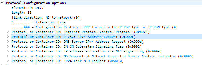
This is kicked off through the Uplink NAS Transport, PDN Connectivity Request from the UE to the network. This includes the IMS APN information, and the UE’s NAS Payload includes the Protocol Configuration Options element (PCO), with a series of fields the UE requires responses from the network. including DNS Server, MTU, etc.
In the PCO the UE also includes the P-CSCF address request, so the network can tell the UE the IP of the P-CSCF to use.
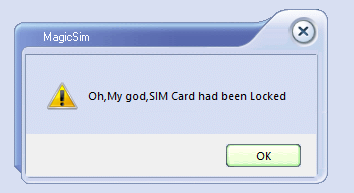
If this is missing it’s because either your APN settings for IMS are not valid, or your device doesn’t have IMS support or isn’t enabling it.(that could be for a few reasons).
Protocol Configuration Options (Unpopulated) used to request information from the Network by the UE
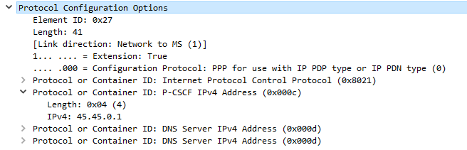
The MME gets this information from the P-GW, and the network responds in the E-RAB Setup Request, Activate default EPS bearer Context Request and includes the Protocol Configuration Options again, this time the fields are populated with their respective values, including the P-CSCF Address;
Once the UE has this setup, the eNB confirms it’s setup the radio resources through the E-RAB Setup Response.
One the eNB has put the radio side of things in place, the UE confirms the bearer assignment has completed successfully through the Uplink NAS Transport, Activate default EPS Bearer Accept, denoting the bearer is now in place.
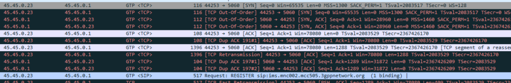
Now the UE has the IP address(s) of the P-CSCF and a bearer to send it over, the UE establishes a TCP socket with the address specified in the P-CSCF IPv4 or IPv6 address, to start communicating with the P-CSCF.
The SIP REGISTER request can now be sent and the REGISTRATION procedure can begin.
IPsec ESP can be used in 3 different ways on the Gm interface between the Ue and the P-CSCF:
Integrity Protection – To prevent tampering
Ciphering – To prevent inception / eavesdropping
Integrity Protection & Ciphering
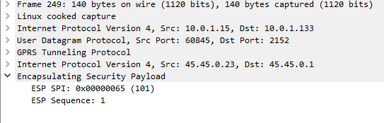
On Wireshark, you’ll see the ESP, but you won’t see the payload contents, just the fact it’s an Encapsulated Security Payload, it’s SPI and Sequence number.
By default, Kamailio’s P-CSCF only acts in Integrity Protection mode, meaning the ESP payloads aren’t actually encrypted, with a few clicks we can get Wireshark to decode this data;
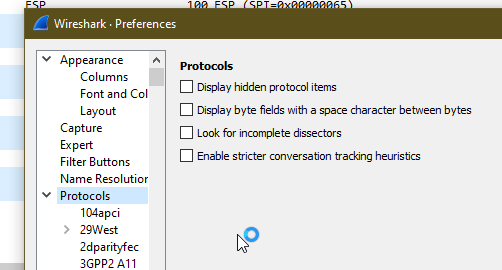
Just open up Wireshark Preferences, expand Protocols and jump to ESP
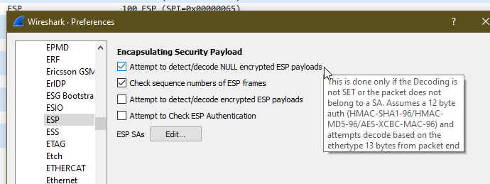
Now we can set the decoding preferences for our ESP payloads,
In our case we’ll tick the “Attempt to detect/decode NULL encrypted ESP payloads” box and close the box by clicking OK button.
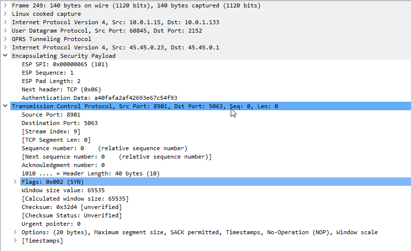
Now Wireshark will scan through all the frames again, anything that’s an ESP payload it will attempt to parse.
Now if we go back to the ESP payload with SQN 1 I showed a screenshot of earlier, we can see the contents are a TCP SYN.
Now we can see what’s going on inside this ESP data between the P-CSCF and the UE!
As a matter of interest if you can see the IK and CK values in the 401 response before they’re stripped you can decode encrypted ESP payloads from Wireshark, from the same Protocol -> ESP section you can load the Ciphering and Integrity keys used in that session to decrypt them.
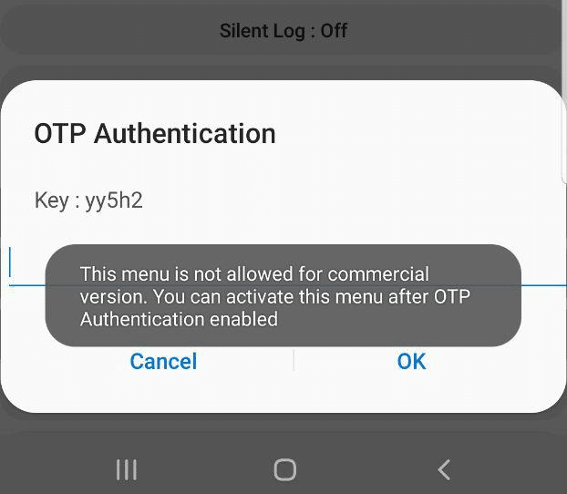
While poking around the development and debugging features on Samsung handsets I found the ability to run IMS Debugging directly from the handset.
Alas, the option is only available in the commercial version, it’s just there for carriers, and requires a One Time Password to unlock.
When tapping on the option a challenge is generated with a key.
Interestingly I noticed that the key changes each time and can reject you even in aeroplane mode, suggesting the authentication happens client side.
This left me thinking – If the authentication happens client side, then the App has to know what the valid password for the key shown is…
Some research revealed you can pull APKs off an Android phone, so I downloaded a utility called “APK Extractor” from the Play store, and used it to extract the Samsung Sysdump utility.
So now I was armed with the APK on my local machine, the next step was to see if I could decompile the APK back into source code.
Some Googling found me an online APK decompiler, which I fed the compiled APK file and got back the source code.
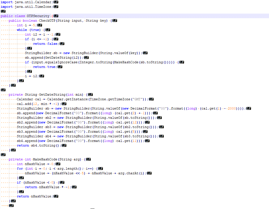
I did some poking around inside the source code, and then I found an interesting directory:
Here’s a screenshot of the vanilla code that came out of the app.
I’m not a Java expert, but even I could see the “CheckOTP” function and understand that that’s what validates the One Time Passwords.
The while loop threw me a little – until I read through the rest of the code; the “key” in the popup box is actually a text string representing the current UNIX timestamp down to the minute level. The correct password is an operation done on the “key”, however the CheckOTP function doesn’t know the challenge key, but has the current time, so generates a challenge key for each timestamp back a few minutes and a few minutes into the future.
I modified the code slightly to allow me to enter the presented “key” and get the correct password back. It’s worth noting you need to act quickly, enter the “key” and enter the response within a minute or so.
In the end I’ve posted the code on an online Java compiler,
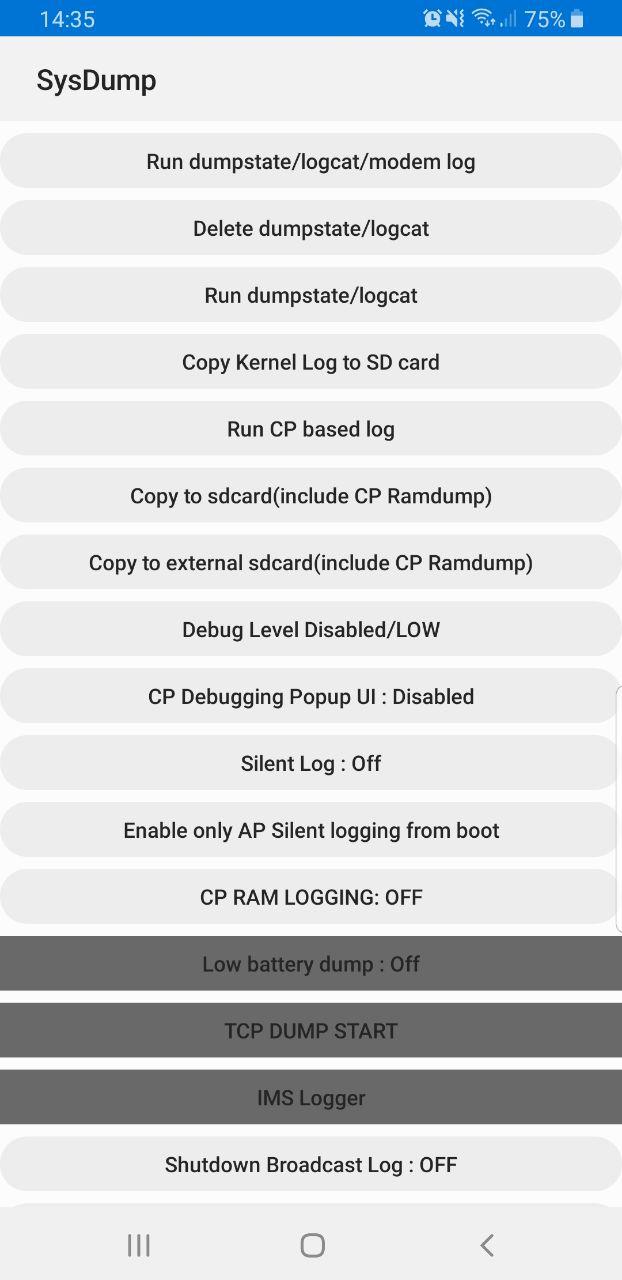
Samsung handsets have a feature built in to allow debugging from the handset, called Sysdump.
Entering *#9900# from the Dialing Screen will bring up the Sysdump App, from here you can dump logs from the device, and run a variety of debugging procedures.
But for private LTE operators, the two most interesting options are by far the TCPDUMP START option and IMS Logger, but both are grayed out.
Tapping on them asks for a one-time password and has a challenge key.
These options are not available in the commercial version of the OS and need to be unlocked with a one time key generated by a tool Samsung for unlocking engineering firmware on handsets.
Luckily this authentication happens client side, which means we can work out the password it’s expecting.
Once you’ve entered the code and successfully unlocked the IMS Debugging tool there’s a few really cool features in the hamburger menu in the top right.
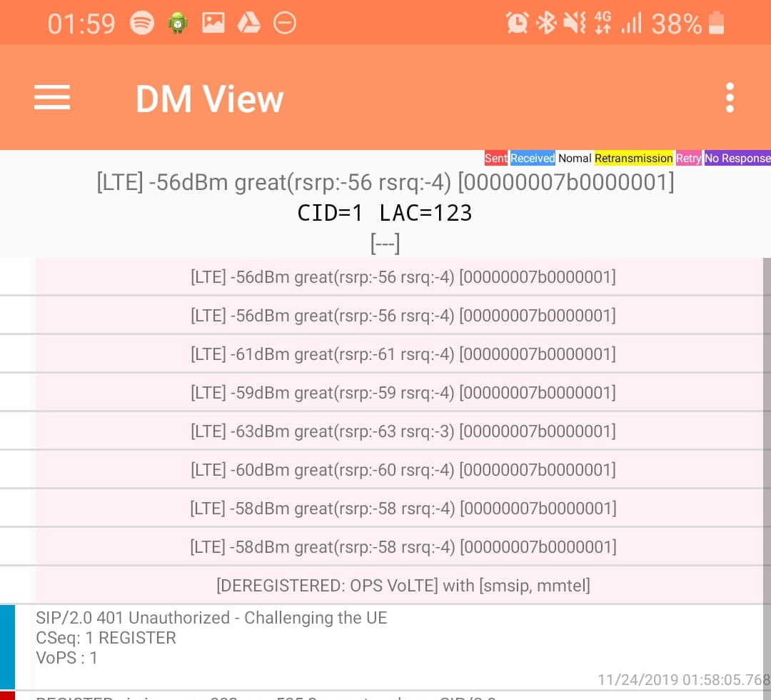
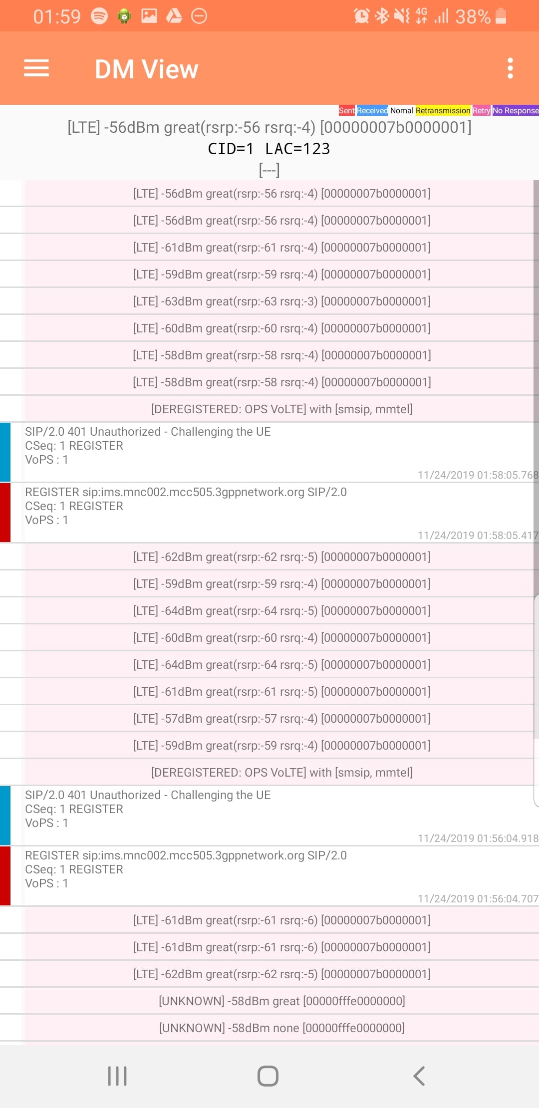
DM View
This shows the SIP / IMS Messaging and the current signal strength parameters (used to determine which RAN type to use (Ie falling back from VoLTE to UMTS / Circuit Switched when the LTE signal strength drops).
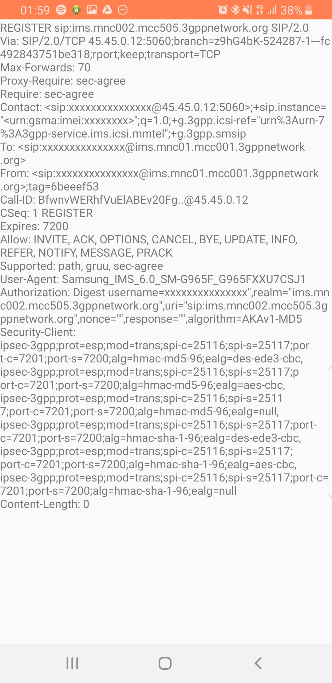
Tapping on the SIP messages expands them and allows you to see the contents of the SIP messages.
Viewing SIP Messaging directly from the handset
Interesting the actual nitty-gritty parameters in the SIP headers are missing, replaced with X for anything “private” or identifiable.
Luckily all this info can be found in the Pcap.
The DM View is great for getting a quick look at what’s going on, on the mobile device itself, without needing a PC.
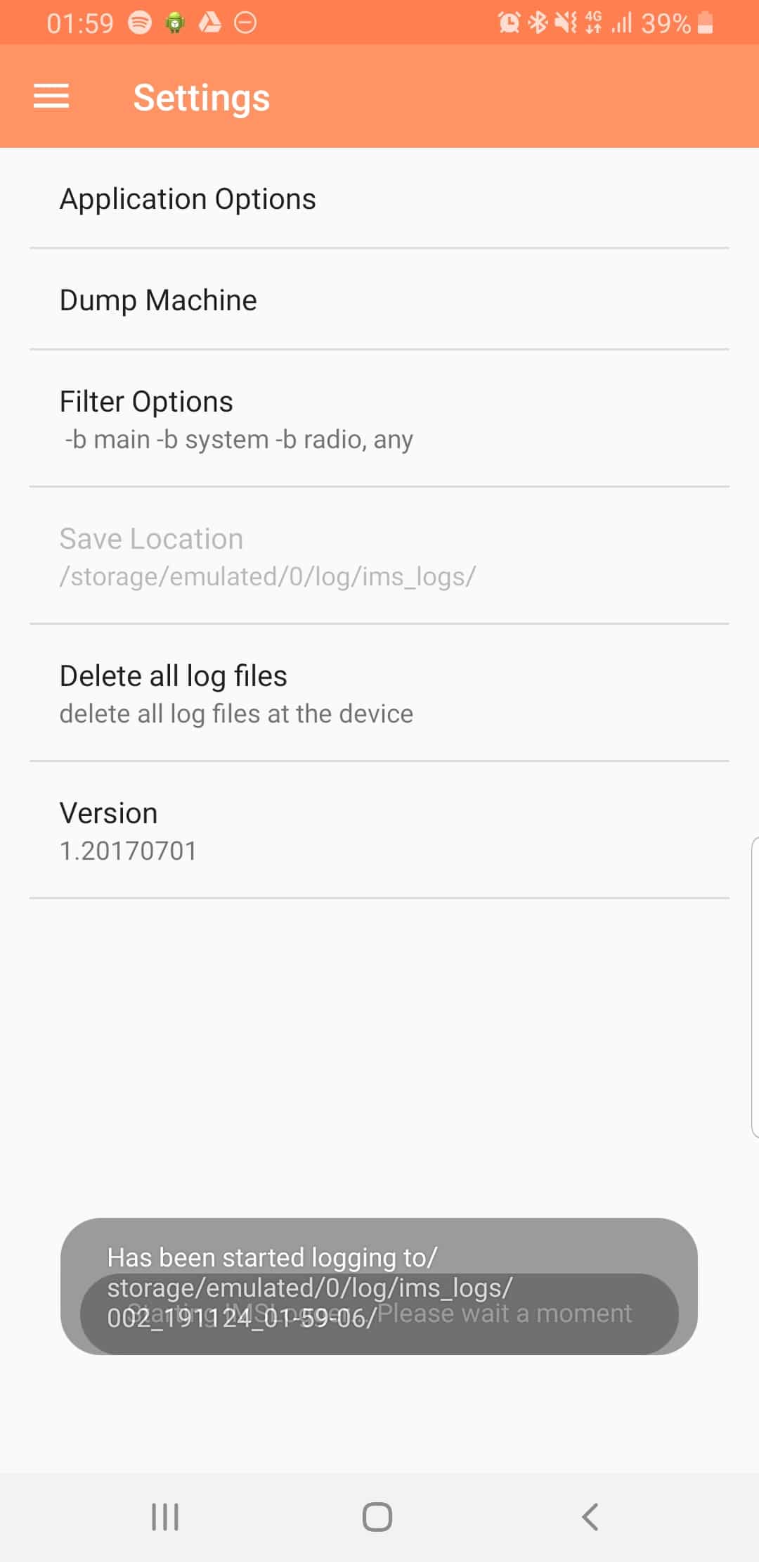
Logging
The real power comes in the logging functions,
There’s a lot of logging options, including screen recording, TCPdump (as in Packet Captures) and Syslog logging.
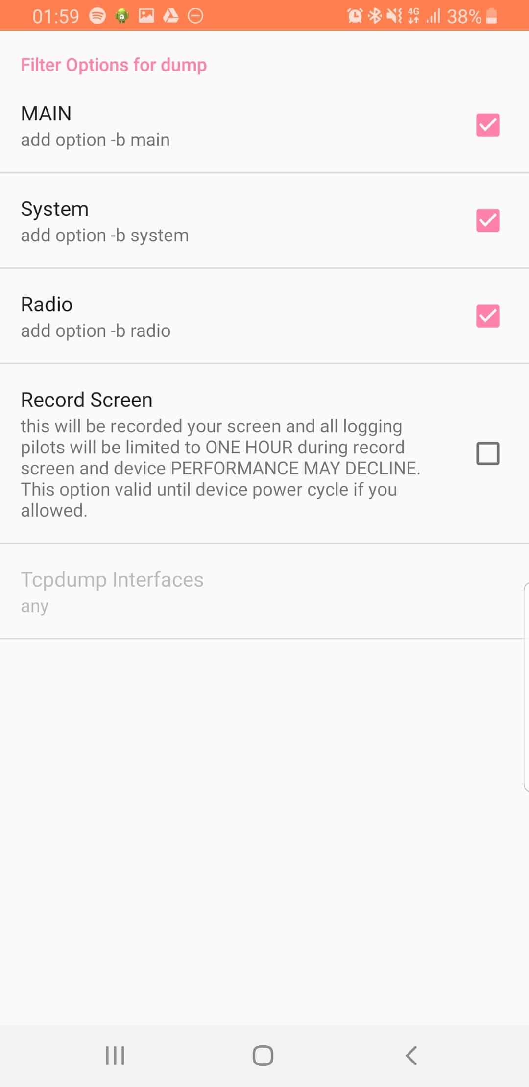
From the hamburger menu we can select the logging parameters we want to change.
From the Filter Options menu we can set what info we’re going to log,